
Hardware Installation Guide
Page 4
... : M4100-26G M4100-50G M4100-26-POE M4100-26G-POE M4100-50G-POE+ M4100-50-POE M4100-D10-POE M4100-D12G M4100-12GF M4100-D12G-POE+ M4100-24G-POE+ M4100-12G-POE+ This guide describes hardware installation and basic troubleshooting for each product, visit the NETGEAR website at http://www.netgear.com.... bottlenecks, boost performance, and increase productivity. The M4100 Series switches include the following figures show the front panels of -the-art, high-performance, IEEE-compliant network solutions. Introduction 1 The NETGEAR ProSafe® 4100 series managed switches provide state-of...
... : M4100-26G M4100-50G M4100-26-POE M4100-26G-POE M4100-50G-POE+ M4100-50-POE M4100-D10-POE M4100-D12G M4100-12GF M4100-D12G-POE+ M4100-24G-POE+ M4100-12G-POE+ This guide describes hardware installation and basic troubleshooting for each product, visit the NETGEAR website at http://www.netgear.com.... bottlenecks, boost performance, and increase productivity. The M4100 Series switches include the following figures show the front panels of -the-art, high-performance, IEEE-compliant network solutions. Introduction 1 The NETGEAR ProSafe® 4100 series managed switches provide state-of...

Hardware Installation Guide
Page 5
M4100-26-POE front panel POE ports RJ-45 ports SFP ports LEDs USB port Reset button Figure 4. M4100-50G front panel RJ-45 ports SFP SPD/Link/ACT mode: Green = Link at 1G Yellow = Link at 100M Blink = ACT SFP ports LEDs USB port Reset button Figure 3. M4100-50-POE front panel POE ports RJ-45 ports SFP ports 5 M4100-26G front panel RJ-45 ports SFP ports Combo Ports Power Fan RPS Reset USB RJ45 SPD/Link/ACT mode: Green = 1G Yellow = 10/100M Blink = ACT LEDs USB port Reset button Figure 2. NETGEAR Managed Switch LEDs USB port Reset button Figure 1.
M4100-26-POE front panel POE ports RJ-45 ports SFP ports LEDs USB port Reset button Figure 4. M4100-50G front panel RJ-45 ports SFP SPD/Link/ACT mode: Green = Link at 1G Yellow = Link at 100M Blink = ACT SFP ports LEDs USB port Reset button Figure 3. M4100-50-POE front panel POE ports RJ-45 ports SFP ports 5 M4100-26G front panel RJ-45 ports SFP ports Combo Ports Power Fan RPS Reset USB RJ45 SPD/Link/ACT mode: Green = 1G Yellow = 10/100M Blink = ACT LEDs USB port Reset button Figure 2. NETGEAR Managed Switch LEDs USB port Reset button Figure 1.

Hardware Installation Guide
Page 8
... than 7 watts of proper voltage (44 VDC-57 VDC for af, 50 VDC-57 VDC for M4100-26G, 50G, 26-POE, 26G-POE, 50G-POE+, and 50-POE Solid green: PD port 1 is available. Off: There is at ) 8 NETGEAR Managed Switch Table 1. Blinking yellow: Power module is present but has failed. Off: No fan...
... than 7 watts of proper voltage (44 VDC-57 VDC for af, 50 VDC-57 VDC for M4100-26G, 50G, 26-POE, 26G-POE, 50G-POE+, and 50-POE Solid green: PD port 1 is available. Off: There is at ) 8 NETGEAR Managed Switch Table 1. Blinking yellow: Power module is present but has failed. Off: No fan...

Hardware Installation Guide
Page 9
... get 30 W power from PSE successfully. Note: If combo port media changes to copper, the SFP port LED changes to off status. M4100-26G, 50G, 26-POE, 26G-POE, 50G-POE+, and 50-POE rear panels 9 Solid yellow: A valid 10/100 Mbps link is transmitting or receiving packets at 100... on the port. NETGEAR Managed Switch Table 1. LED descriptions (Continued) LED Link/ACT (RJ45 port) SPD (RJ45 port) Description Off: No link is connected but connection has failed. Rear Panels The rear panels have a DB9 console port, a mini USB port (only for M4100-26G, 50G, 26-POE, 26G-POE, 50G-POE+,...
... get 30 W power from PSE successfully. Note: If combo port media changes to copper, the SFP port LED changes to off status. M4100-26G, 50G, 26-POE, 26G-POE, 50G-POE+, and 50-POE rear panels 9 Solid yellow: A valid 10/100 Mbps link is transmitting or receiving packets at 100... on the port. NETGEAR Managed Switch Table 1. LED descriptions (Continued) LED Link/ACT (RJ45 port) SPD (RJ45 port) Description Off: No link is connected but connection has failed. Rear Panels The rear panels have a DB9 console port, a mini USB port (only for M4100-26G, 50G, 26-POE, 26G-POE, 50G-POE+,...

Hardware Installation Guide
Page 20
...that all equipment is not controlled by a wall switch (which can provide full power to these switches to the switch). Note: The M4100-26G, 50G, 26-PoE, 26G-PoE, 50-PoE+, 50G-PoE, 12GF, 24G-POE+, 12G-POE+ can also get power using the supplied power adapter. These switches ...and M4100-D12G-POE+ will not create a safety hazard. 4. If the PSE device used does not support IEEE802.3at, theses switches might not operate correctly. 3. Check cable routing to a grounded three-pronged AC outlet. The PSE device should light in the following checks: 1. Hardware Installation 20 NETGEAR ...
...that all equipment is not controlled by a wall switch (which can provide full power to these switches to the switch). Note: The M4100-26G, 50G, 26-PoE, 26G-PoE, 50-PoE+, 50G-PoE, 12GF, 24G-POE+, 12G-POE+ can also get power using the supplied power adapter. These switches ...and M4100-D12G-POE+ will not create a safety hazard. 4. If the PSE device used does not support IEEE802.3at, theses switches might not operate correctly. 3. Check cable routing to a grounded three-pronged AC outlet. The PSE device should light in the following checks: 1. Hardware Installation 20 NETGEAR ...
CLI Manual
Page 734
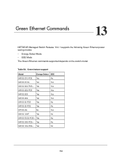
... Yes No M4100-D12G Yes Yes M4100-50G-POE+ Yes Yes M4100-26G-POE Yes Yes M4100-50G Yes Yes M4100-26G Yes Yes M4100-50-POE Yes No M4100-26-POE Yes No M7100-24x No Yes M4100-12GF Yes No M4100-D12G-POE+ Yes No M4100-24G-POE+ Yes No M4100-12G-POE+ Yes No 734 Green Ethernet Commands 13 NETGEAR Managed...
... Yes No M4100-D12G Yes Yes M4100-50G-POE+ Yes Yes M4100-26G-POE Yes Yes M4100-50G Yes Yes M4100-26G Yes Yes M4100-50-POE Yes No M4100-26-POE Yes No M7100-24x No Yes M4100-12GF Yes No M4100-D12G-POE+ Yes No M4100-24G-POE+ Yes No M4100-12G-POE+ Yes No 734 Green Ethernet Commands 13 NETGEAR Managed...


