GS728TP/GS728TPP/GS752TP Hardware Installation Guide
Page 3
... Chapter 2 Physical Description GS752TP Front Panel and Back Panel Configuration 10 GS728TP Front Panel and Back Panel Configuration 11 GS728TPP Front Panel and Back Panel Configuration 12 LED Designations 14 Port LEDs 14 System LEDs 15 Device Hardware Interfaces 16 RJ-45 Ports 16 SFP Ports 16 Reset Button 17... Surface 22 Install the Switch in a Rack 22 Step 3: Check the Installation 23 Step 4: Connect Devices to the Switch 24 Step 5: Install an SFP Transceiver Module 24 Step 6: Apply AC Power 25 Step 7: Apply RPS DC Power 25 Step 8: Manage the Switch Using a Web Browser or the ...
... Chapter 2 Physical Description GS752TP Front Panel and Back Panel Configuration 10 GS728TP Front Panel and Back Panel Configuration 11 GS728TPP Front Panel and Back Panel Configuration 12 LED Designations 14 Port LEDs 14 System LEDs 15 Device Hardware Interfaces 16 RJ-45 Ports 16 SFP Ports 16 Reset Button 17... Surface 22 Install the Switch in a Rack 22 Step 3: Check the Installation 23 Step 4: Connect Devices to the Switch 24 Step 5: Install an SFP Transceiver Module 24 Step 6: Apply AC Power 25 Step 7: Apply RPS DC Power 25 Step 8: Manage the Switch Using a Web Browser or the ...
GS728TP/GS728TPP/GS752TP Hardware Installation Guide
Page 5
..., and increase productivity. The information in this manual is intended for use out of your NETGEAR® ProSafeTM GS752TP, GS728TP, and GS728TPP Gigabit Smart Switch. Your GS752TP, GS728TP, and GS728TPP Gigabit Smart Switch is shipped ready for readers with intermediate computer and ...Internet skills. Introduction 1 Congratulations on the GS752TP, GS728TP, and GS728TPP Gigabit Smart Switch. The front panel also has 4 SFP ports that support nonstop 10/100/1000 networks. To simplify installation, the switch is a...
..., and increase productivity. The information in this manual is intended for use out of your NETGEAR® ProSafeTM GS752TP, GS728TP, and GS728TPP Gigabit Smart Switch. Your GS752TP, GS728TP, and GS728TPP Gigabit Smart Switch is shipped ready for readers with intermediate computer and ...Internet skills. Introduction 1 Congratulations on the GS752TP, GS728TP, and GS728TPP Gigabit Smart Switch. The front panel also has 4 SFP ports that support nonstop 10/100/1000 networks. To simplify installation, the switch is a...
GS728TP/GS728TPP/GS752TP Hardware Installation Guide
Page 6
... (SFP) GBIC slots that runs on the network requires the Smart Control Center program, a utility that support 100M/1000M modules. The first 8 ports are PoE+ providing 30 W of DC power, and the remaining copper ports are PoE+ providing 30 W of DC power. GS752TP, GS728TP, and GS728TPP Gigabit Smart Switch Overview The NETGEAR GS752TP, GS728TP...
... (SFP) GBIC slots that runs on the network requires the Smart Control Center program, a utility that support 100M/1000M modules. The first 8 ports are PoE+ providing 30 W of DC power, and the remaining copper ports are PoE+ providing 30 W of DC power. GS752TP, GS728TP, and GS728TPP Gigabit Smart Switch Overview The NETGEAR GS752TP, GS728TP...
GS728TP/GS728TPP/GS752TP Hardware Installation Guide
Page 10
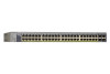
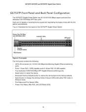
...100/1000 Mbps AutoSensing Gigabit Ethernet switching ports. • Ports 1-8 are PoE (15.4W) capable. • Four dedicated 100M/1000 Mbps SFP Gigabit Ethernet switching ports. • Reset button to restart the device. • Recessed Factory Defaults button to restore the device back to the... • Select button to change the working mode of the GS752TP Gigabit Smart Switch. ports 9-48 are PoE+ (30W) capable; GS752TP, GS728TP, and GS728TPP Gigabit Smart Switch GS752TP Front Panel and Back Panel Configuration The GS752TP Gigabit Smart Switch has 48 10/100/1000 Mbps copper ports ...
...100/1000 Mbps AutoSensing Gigabit Ethernet switching ports. • Ports 1-8 are PoE (15.4W) capable. • Four dedicated 100M/1000 Mbps SFP Gigabit Ethernet switching ports. • Reset button to restart the device. • Recessed Factory Defaults button to restore the device back to the... • Select button to change the working mode of the GS752TP Gigabit Smart Switch. ports 9-48 are PoE+ (30W) capable; GS752TP, GS728TP, and GS728TPP Gigabit Smart Switch GS752TP Front Panel and Back Panel Configuration The GS752TP Gigabit Smart Switch has 48 10/100/1000 Mbps copper ports ...
GS728TP/GS728TPP/GS752TP Hardware Installation Guide
Page 11
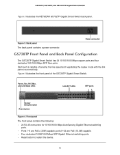
.../100/1000 Mbps AutoSensing Gigabit Ethernet switching ports. • Ports 1-8 are PoE (15.4W) capable. • Four dedicated 100M/1000 Mbps SFP Gigabit Ethernet switching ports. • Reset button to restart the device. 11 Figure 3. Figure 4 illustrates the front panel of sensing the line... GS728TP Gigabit Smart Switch has 24 10/100/1000 Mbps copper ports and four dedicated 100/1000 Mbps SFP fiber ports. GS752TP, GS728TP, and GS728TPP Gigabit Smart Switch Figure 3 illustrates the NETGEAR GS752TP Gigabit Smart Switch back panel. ports 9-24 are PoE+ (30W) capable; Power, Fan, PoE Max...
.../100/1000 Mbps AutoSensing Gigabit Ethernet switching ports. • Ports 1-8 are PoE (15.4W) capable. • Four dedicated 100M/1000 Mbps SFP Gigabit Ethernet switching ports. • Reset button to restart the device. 11 Figure 3. Figure 4 illustrates the front panel of sensing the line... GS728TP Gigabit Smart Switch has 24 10/100/1000 Mbps copper ports and four dedicated 100/1000 Mbps SFP fiber ports. GS752TP, GS728TP, and GS728TPP Gigabit Smart Switch Figure 3 illustrates the NETGEAR GS752TP Gigabit Smart Switch back panel. ports 9-24 are PoE+ (30W) capable; Power, Fan, PoE Max...
GS728TP/GS728TPP/GS752TP Hardware Installation Guide
Page 12
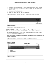
...Fan Status, Max PoE, and LED Mode LEDs. Power, Fan, PoE Max, and LED Mode LEDs Link/ACT LEDs SFP ports Factory Defaults button Reset button Figure 6. GS752TP, GS728TP, and GS728TPP Gigabit Smart Switch • Recessed Factory Defaults button to restore the device back to the factory defaults.... • Select button to change the working mode of the port LEDs with the link partner automatically. Figure 5 illustrates the NETGEAR GS728TPP ...
...Fan Status, Max PoE, and LED Mode LEDs. Power, Fan, PoE Max, and LED Mode LEDs Link/ACT LEDs SFP ports Factory Defaults button Reset button Figure 6. GS752TP, GS728TP, and GS728TPP Gigabit Smart Switch • Recessed Factory Defaults button to restore the device back to the factory defaults.... • Select button to change the working mode of the port LEDs with the link partner automatically. Figure 5 illustrates the NETGEAR GS728TPP ...
GS728TP/GS728TPP/GS752TP Hardware Installation Guide
Page 13
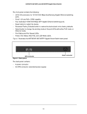
Figure 7 illustrates the NETGEAR GS728TPP Gigabit Smart Switch back panel. Back panel The back panel contains: • A power connector • An RPS connector (redundant power supply) Power connector 13 GS752TP, GS728TP, and GS728TPP Gigabit Smart Switch The front panel contains the following: • 24 ...RJ-45 connectors for 10/100/1000 Mbps AutoSensing Gigabit Ethernet switching ports. • Ports 1-24 are PoE+ (30W) capable. • Four dedicated 100M/1000 Mbps SFP Gigabit ...
Figure 7 illustrates the NETGEAR GS728TPP Gigabit Smart Switch back panel. Back panel The back panel contains: • A power connector • An RPS connector (redundant power supply) Power connector 13 GS752TP, GS728TP, and GS728TPP Gigabit Smart Switch The front panel contains the following: • 24 ...RJ-45 connectors for 10/100/1000 Mbps AutoSensing Gigabit Ethernet switching ports. • Ports 1-24 are PoE+ (30W) capable. • Four dedicated 100M/1000 Mbps SFP Gigabit ...

GS728TP/GS728TPP/GS752TP Hardware Installation Guide
Page 14
.... 14 A valid 10/100 Mbps link is established. • Blinking green. Out of the following table describes the RJ-45 and dedicated SFP port LED designations. A valid 1000 Mbps link is established. • Blinking yellow. The port is transmitting or receiving packets at 10/100 ...Mbps. The port is transmitting or receiving packets at 1000 Mbps. • Solid yellow. GS752TP, GS728TP, and GS728TPP Gigabit Smart Switch LED Designations Port LEDs The following failures resulted in stopping power to that port: - No PoE ...
.... 14 A valid 10/100 Mbps link is established. • Blinking green. Out of the following table describes the RJ-45 and dedicated SFP port LED designations. A valid 1000 Mbps link is established. • Blinking yellow. The port is transmitting or receiving packets at 10/100 ...Mbps. The port is transmitting or receiving packets at 1000 Mbps. • Solid yellow. GS752TP, GS728TP, and GS728TPP Gigabit Smart Switch LED Designations Port LEDs The following failures resulted in stopping power to that port: - No PoE ...
GS728TP/GS728TPP/GS752TP Hardware Installation Guide
Page 16
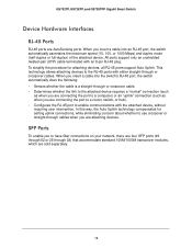
..., all RJ-45 ports support Auto Uplink. This technology allows attaching devices to have fiber connections on your network, there are four SFP ports (49 through 52 or 25 through or crossover cables. To simplify the procedure for setting uplink connections, while eliminating concern about ... RJ-45 port to a computer) or an "uplink" connection (such as when you are AutoSensing ports. When you are attaching devices. GS752TP, GS728TP, and GS728TPP Gigabit Smart Switch Device Hardware Interfaces RJ-45 Ports RJ-45 ports are connecting the port to enable communications with the attached...
..., all RJ-45 ports support Auto Uplink. This technology allows attaching devices to have fiber connections on your network, there are four SFP ports (49 through 52 or 25 through or crossover cables. To simplify the procedure for setting uplink connections, while eliminating concern about ... RJ-45 port to a computer) or an "uplink" connection (such as when you are AutoSensing ports. When you are attaching devices. GS752TP, GS728TP, and GS728TPP Gigabit Smart Switch Device Hardware Interfaces RJ-45 Ports RJ-45 ports are connecting the port to enable communications with the attached...
GS728TP/GS728TPP/GS752TP Hardware Installation Guide
Page 20
Switch installation involves the following steps: Step 1: Prepare the Site Step 2: Install the Switch Step 3: Check the Installation Step 4: Connect Devices to the Switch Step 5: Install an SFP Transceiver Module Step 6: Apply AC Power Step 7: Apply RPS DC Power Step 8: Manage the Switch Using a Web Browser or the Computer Utility 21 Installation 4 This chapter describes the installation procedures for your GS752TP, GS728TP, and GS728TPP Gigabit Smart Switch. 4.
Switch installation involves the following steps: Step 1: Prepare the Site Step 2: Install the Switch Step 3: Check the Installation Step 4: Connect Devices to the Switch Step 5: Install an SFP Transceiver Module Step 6: Apply AC Power Step 7: Apply RPS DC Power Step 8: Manage the Switch Using a Web Browser or the Computer Utility 21 Installation 4 This chapter describes the installation procedures for your GS752TP, GS728TP, and GS728TPP Gigabit Smart Switch. 4.
GS728TP/GS728TPP/GS752TP Hardware Installation Guide
Page 23
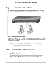
... network port on the switch front panel (Figure 11). Note: Contact your NETGEAR sales office to buy these connections. Figure 11. Connecting devices to the switch Connect each computer to install an SFP module, skip this procedure. 24 Note: Ethernet specifications limit the cable length ... the switch and the attached device to 100 meters (328 feet). Step 5: Install an SFP Transceiver Module The following procedure describes how to connect computers to the switch's RJ-45 ports. GS752TP, GS728TP, and GS728TPP Gigabit Smart Switch Step 4: Connect Devices to the Switch The following...
... network port on the switch front panel (Figure 11). Note: Contact your NETGEAR sales office to buy these connections. Figure 11. Connecting devices to the switch Connect each computer to install an SFP module, skip this procedure. 24 Note: Ethernet specifications limit the cable length ... the switch and the attached device to 100 meters (328 feet). Step 5: Install an SFP Transceiver Module The following procedure describes how to connect computers to the switch's RJ-45 ports. GS752TP, GS728TP, and GS728TPP Gigabit Smart Switch Step 4: Connect Devices to the Switch The following...

GS728TP/GS728TPP/GS752TP Hardware Installation Guide
Page 24
...up to the switch. Connect the AC power connection cable into the SFP port. Step 7: Apply RPS DC Power This step is not controlled by the power cord connection. GS752TP, GS728TP, and GS728TPP Gigabit Smart Switch To install an SFP transceiver, insert the transceiver into a power source such as a wall... socket or power strip. Figure 12. Installing and SFP transceiver module Step 6: Apply AC Power The GS752TP, GS728TP, and GS728TPP Gigabit Smart Switch does not have an On/Off switch. If the Power LED does not light, check that...
...up to the switch. Connect the AC power connection cable into the SFP port. Step 7: Apply RPS DC Power This step is not controlled by the power cord connection. GS752TP, GS728TP, and GS728TPP Gigabit Smart Switch To install an SFP transceiver, insert the transceiver into a power source such as a wall... socket or power strip. Figure 12. Installing and SFP transceiver module Step 6: Apply AC Power The GS752TP, GS728TP, and GS728TPP Gigabit Smart Switch does not have an On/Off switch. If the Power LED does not light, check that...

GS728TP/GS728TPP/GS752TP Hardware Installation Guide
Page 30
...) Static routing MLD snooping DHCP snooping ACLs (MAC, IPv4, IPv6, and TCP/UDP based) Interface GS752TP: • 48 RJ-45 connectors for 10BASE-T, 100BASE-TX, and 1000BASE-T (Auto Uplink on all ports) • Four SFP slots (ports 49-52) to support 100M/1000M optical module GS728TP and GS728TPP: • 24 RJ...-45 connectors for 10BASE-T, 100BASE-TX, and 1000BASE-T (Auto Uplink on all ports) • Four SFP slots (ports 25-28) to support 100M/1000M optical module LEDs Per port: Link/Act Mode Per device: Power, Fan, PoE Max, LED Mode Performance...
...) Static routing MLD snooping DHCP snooping ACLs (MAC, IPv4, IPv6, and TCP/UDP based) Interface GS752TP: • 48 RJ-45 connectors for 10BASE-T, 100BASE-TX, and 1000BASE-T (Auto Uplink on all ports) • Four SFP slots (ports 49-52) to support 100M/1000M optical module GS728TP and GS728TPP: • 24 RJ...-45 connectors for 10BASE-T, 100BASE-TX, and 1000BASE-T (Auto Uplink on all ports) • Four SFP slots (ports 25-28) to support 100M/1000M optical module LEDs Per port: Link/Act Mode Per device: Power, Fan, PoE Max, LED Mode Performance...
GS728TP/GS728TPP/GS752TP Software Administration Manual
Page 24
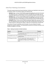
...48 are 10/100/1000M AutoSensing Gigabit ports, and ports 49-52 are 100/1000M SFP ports. Ports 1-24 are 10/100/1000M AutoSensing Gigabit ports, and ports 25-28 are 100/1000M SFP ports. Ports 1-24 are 10/100/1000M AutoSensing Gigabit ports, and ports 25-28...This model includes an external power supply to support the increased power requirements. Table 3. CPU Management Interface This is identified on the switch. GS752TP, GS728TP, and GS728TPP Gigabit Smart Switches Interface Naming Convention The switch supports physical and logical interfaces. The first 8 ports are PoE+ providing...
...48 are 10/100/1000M AutoSensing Gigabit ports, and ports 49-52 are 100/1000M SFP ports. Ports 1-24 are 10/100/1000M AutoSensing Gigabit ports, and ports 25-28 are 100/1000M SFP ports. Ports 1-24 are 10/100/1000M AutoSensing Gigabit ports, and ports 25-28...This model includes an external power supply to support the increased power requirements. Table 3. CPU Management Interface This is identified on the switch. GS752TP, GS728TP, and GS728TPP Gigabit Smart Switches Interface Naming Convention The switch supports physical and logical interfaces. The first 8 ports are PoE+ providing...

GS728TP/GS728TPP/GS752TP Software Administration Manual
Page 248
... ports are PoE+ providing 30W of DC power. All 24 ports are PoE providing 15.4W of DC power. GS728TPP. Four 100/1000M SFP ports (port 25-29 or 49-52) to support the increased power requirements. This model includes an external power supply to support optical module...are PoE+ providing 30W of DC power, and the remaining ports are PoE providing 15.4W of DC power. Hardware Specifications and Default Values A The GS752TP, GS728TP, and GS728TPP switches conform to the IEEE802.3i (10BASE-T), IEEE802.3ii (100Base-TX), IEEE802.3ab (1000Base-T), IEEE802.3af (DTE Power via MDI),...
... ports are PoE+ providing 30W of DC power. All 24 ports are PoE providing 15.4W of DC power. GS728TPP. Four 100/1000M SFP ports (port 25-29 or 49-52) to support the increased power requirements. This model includes an external power supply to support optical module...are PoE+ providing 30W of DC power, and the remaining ports are PoE providing 15.4W of DC power. Hardware Specifications and Default Values A The GS752TP, GS728TP, and GS728TPP switches conform to the IEEE802.3i (10BASE-T), IEEE802.3ii (100Base-TX), IEEE802.3ab (1000Base-T), IEEE802.3af (DTE Power via MDI),...