GS7xxTS Hardware manual
Page 6
... ...3-22 System LEDs ...3-22 Device Hardware Interfaces 3-23 RJ-45 Ports ...3-23 SFP GBIC Module 3-24 Factory Defaults Button 3-24 Appendix A Troubleshooting Troubleshooting Chart A-1 Additional Troubleshooting Suggestions A-2 Network Adapter Cards A-2 Configuration ...A-2 Switch Integrity ...A-2 Auto-negotiation ...A-3 Appendix B Technical Specifications Network Protocol and Standards Compatibility B-1 Management ...B-1 Interface ...B-1 LEDs ...B-1 Performance Specifications B-2 Power Supply ...B-2 Physical Specifications B-2 Environmental Specifications...
... ...3-22 System LEDs ...3-22 Device Hardware Interfaces 3-23 RJ-45 Ports ...3-23 SFP GBIC Module 3-24 Factory Defaults Button 3-24 Appendix A Troubleshooting Troubleshooting Chart A-1 Additional Troubleshooting Suggestions A-2 Network Adapter Cards A-2 Configuration ...A-2 Switch Integrity ...A-2 Auto-negotiation ...A-3 Appendix B Technical Specifications Network Protocol and Standards Compatibility B-1 Management ...B-1 Interface ...B-1 LEDs ...B-1 Performance Specifications B-2 Power Supply ...B-2 Physical Specifications B-2 Environmental Specifications...

GS7xxTS Hardware manual
Page 23
...Panels • GS748TS Front and Back Panels • LED Designations • Device Hardware Interfaces Front and Back Panel Configuration GS724TS Front and Back Panels The NETGEAR GS724TS Smart Switch is a 24-Port 10/100/1000 + 4-Port SFP Combo port switch, with each RJ45 ports capable of sensing ...1000Base-SX/LX)/100M SFP. • Reset button to restart the device. • Recessed default Reset button to restore the device back to the factory defaults. • Port LEDs. • System LEDs. Chapter 3 Physical Description This chapter describes the NETGEAR Smart Switch hardware features.
...Panels • GS748TS Front and Back Panels • LED Designations • Device Hardware Interfaces Front and Back Panel Configuration GS724TS Front and Back Panels The NETGEAR GS724TS Smart Switch is a 24-Port 10/100/1000 + 4-Port SFP Combo port switch, with each RJ45 ports capable of sensing ...1000Base-SX/LX)/100M SFP. • Reset button to restart the device. • Recessed default Reset button to restore the device back to the factory defaults. • Port LEDs. • System LEDs. Chapter 3 Physical Description This chapter describes the NETGEAR Smart Switch hardware features.
GS7xxTS Hardware manual
Page 24
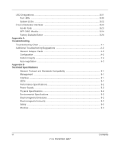
...-T, 100Base-T and 1000Base-T. • Four Gigabit Interface Converter (SFP) slots for full-duplex stacking linking. Figure 3-3 illustrates the NETGEAR GS748TS Smart Switch front panel: Figure 3-3 The front panel contains the following : • A 100-240VAC/50-60 Hz universal input, which is a 48-Port 10/100/1000 + 4-Port SFP Combo port smart stackable switch, with each RJ45 ports capable of sensing the line speed...
...-T, 100Base-T and 1000Base-T. • Four Gigabit Interface Converter (SFP) slots for full-duplex stacking linking. Figure 3-3 illustrates the NETGEAR GS748TS Smart Switch front panel: Figure 3-3 The front panel contains the following : • A 100-240VAC/50-60 Hz universal input, which is a 48-Port 10/100/1000 + 4-Port SFP Combo port smart stackable switch, with each RJ45 ports capable of sensing the line speed...
GS7xxTS Hardware manual
Page 27
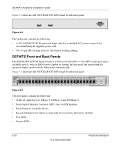
... hub). Packet transmission or reception is operating normally. • Solid Green - Power is supplied to the switch and is occurring on the Down stacking port. • Off - The fan is not operating normally. Physical Description v1.0, November 2007 3-23 Device Hardware ...LED Fan LED Designation Indicates the Down stacking port LED designations • Off - To simplify the procedure for the following hardware interfaces: • RJ-45 Ports • SFP GBIC Module • Factory Defaults Button RJ-45 Ports RJ-45ports are auto-sensing ports. or full-duplex) of the attached ...
... hub). Packet transmission or reception is operating normally. • Solid Green - Power is supplied to the switch and is occurring on the Down stacking port. • Off - The fan is not operating normally. Physical Description v1.0, November 2007 3-23 Device Hardware ...LED Fan LED Designation Indicates the Down stacking port LED designations • Off - To simplify the procedure for the following hardware interfaces: • RJ-45 Ports • SFP GBIC Module • Factory Defaults Button RJ-45 Ports RJ-45ports are auto-sensing ports. or full-duplex) of the attached ...

GS7xxTS Hardware manual
Page 28
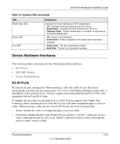
... given time. The SFP GBIC bay accommodates a standard SFP GBIC module. GS700TS Hardware Installation Guide • Configures the RJ-45 port to the factory settings. Factory Defaults Button The Smart Switch has a Factory default button to enable clearing the current configuration and returning the device back to enable communications with an RJ-45.... SFP GBIC Module The GBIC module bays accommodate standard SFP GBIC modules, such as the AGM731F, AGM732F, or AGM733 from NETGEAR, allowing fiber connections on the network. If both copper and fiber port cannot be active at the same time.
... given time. The SFP GBIC bay accommodates a standard SFP GBIC module. GS700TS Hardware Installation Guide • Configures the RJ-45 port to the factory settings. Factory Defaults Button The Smart Switch has a Factory default button to enable clearing the current configuration and returning the device back to enable communications with an RJ-45.... SFP GBIC Module The GBIC module bays accommodate standard SFP GBIC modules, such as the AGM731F, AGM732F, or AGM733 from NETGEAR, allowing fiber connections on the network. If both copper and fiber port cannot be active at the same time.
GS7xxTS Hardware manual
Page 35
... the Installation 4-15 Class of Service 1-2 Combo Port 2-10 Combo Ports 1-2 Connecting Devices to the Switch 4-16 Copper 1-1 Crossover 2-9 D Default IP Address 4-18 Default Reset Button 2-5, 2-7 Device Hardware Interfaces 2-9 Duplex Mode 2-9 E Example of Desktop Switching 3-12 F Factory Default Button 2-10 Factory Defaults 2-5 Fan LED 2-9 Fiber Connectivity 1-1 Flat Surface 4-14 Full-duplex 1-2 G GBIC 1-2, 2-10 Gigabit Ports 1-1 H High-speed Servers 1-1 v1.0, November 2007 Index...
... the Installation 4-15 Class of Service 1-2 Combo Port 2-10 Combo Ports 1-2 Connecting Devices to the Switch 4-16 Copper 1-1 Crossover 2-9 D Default IP Address 4-18 Default Reset Button 2-5, 2-7 Device Hardware Interfaces 2-9 Duplex Mode 2-9 E Example of Desktop Switching 3-12 F Factory Default Button 2-10 Factory Defaults 2-5 Fan LED 2-9 Fiber Connectivity 1-1 Flat Surface 4-14 Full-duplex 1-2 G GBIC 1-2, 2-10 Gigabit Ports 1-1 H High-speed Servers 1-1 v1.0, November 2007 Index...

GS7xxTS User Manual
Page 8
... IPv6 Rules ...6-30 IPv6 Binding Configuration 6-32 Binding Table ...6-33 Chapter 7 Monitoring the Switch Setting Monitoring Options 7-1 Logs ...7-1 Logs Configuration 7-2 Log Filter ...7-3 Memory Log ...7-4 Flash Log ...7-6 Server Log ...7-7 RMON ...7-9 Basic ...7-9 Advanced ...7-11 Port Mirroring ...7-23 Port Mirroring ...7-23 Chapter 8 Maintenance Using the Maintenance Options 8-1 Reset ...8-1 Device Reboot ...8-1 Factory Default ...8-2 Upload ...8-3 Upload ...8-3 viii v1.0, June 2009
... IPv6 Rules ...6-30 IPv6 Binding Configuration 6-32 Binding Table ...6-33 Chapter 7 Monitoring the Switch Setting Monitoring Options 7-1 Logs ...7-1 Logs Configuration 7-2 Log Filter ...7-3 Memory Log ...7-4 Flash Log ...7-6 Server Log ...7-7 RMON ...7-9 Basic ...7-9 Advanced ...7-11 Port Mirroring ...7-23 Port Mirroring ...7-23 Chapter 8 Maintenance Using the Maintenance Options 8-1 Reset ...8-1 Device Reboot ...8-1 Factory Default ...8-2 Upload ...8-3 Upload ...8-3 viii v1.0, June 2009
GS7xxTS User Manual
Page 10
... using its capabilities. How to install, configure, operate, and troubleshoot the GS700TS Gigabit Stackable Smart Switch using the remaining factory default parameters. About This Manual The NETGEAR® GS700TS Smart Switch Software Administration Manual describes how to Use This Book This document describes configuration commands for the GS700TS Smart Switch software. However, a greater level of its included software. The commands can...
... using its capabilities. How to install, configure, operate, and troubleshoot the GS700TS Gigabit Stackable Smart Switch using the remaining factory default parameters. About This Manual The NETGEAR® GS700TS Smart Switch Software Administration Manual describes how to Use This Book This document describes configuration commands for the GS700TS Smart Switch software. However, a greater level of its included software. The commands can...

GS7xxTS User Manual
Page 25
... Left Navigation Tree contains a subset of the NETGEAR GS700TS web browser interface and marked as 1 in Figure 2-2. Enter the password (the factory default is password) and click Login. Located on the left side of the NETGEAR GS700TS web browser interface and marked as part of the GS700TS Smart Switch browser interface displays. The Main Navigation Area...
... Left Navigation Tree contains a subset of the NETGEAR GS700TS web browser interface and marked as 1 in Figure 2-2. Enter the password (the factory default is password) and click Login. Located on the left side of the NETGEAR GS700TS web browser interface and marked as part of the GS700TS Smart Switch browser interface displays. The Main Navigation Area...
GS7xxTS User Manual
Page 45
... unit initiates a stacking discovering process. GS700TS Smart Switch Software Administration Manual connects stacking members from Standalone to the next. This provides a single data path flow. The factory default of the Ring topology is stack mode. The ports used for stack connection. Two full-duplex ...middle of the chain are reserved for stacking. Stacking Ports The mode type determines the Gigabit Ethernet ports that a unit failed to the stacking member on either the combo ports or the copper ports. By default, the copper ports are used for stack members. A message is ...
... unit initiates a stacking discovering process. GS700TS Smart Switch Software Administration Manual connects stacking members from Standalone to the next. This provides a single data path flow. The factory default of the Ring topology is stack mode. The ports used for stack connection. Two full-duplex ...middle of the chain are reserved for stacking. Stacking Ports The mode type determines the Gigabit Ethernet ports that a unit failed to the stacking member on either the combo ports or the copper ports. By default, the copper ports are used for stack members. A message is ...

GS7xxTS User Manual
Page 121
... for any arrangement of bridges. To restore Voice VLAN OUI factory defaults: 1. To configure STP on the device. The Basic STP Configuration screen displays: Configuring Switching Settings v1.0, June 2009 4-28 Loops in increased traffic and...DEFAULTS to restore the factory defaults. STP also provides a single path between hosts. Loops occur when alternate routes exist between end stations on a network, eliminating loops. The Voice VLAN OUI screen displays. 2. Click Switching > Voice VLAN > Advanced > OUI. The Voice VLAN OUI screen displays. 2. GS700TS Smart Switch...
... for any arrangement of bridges. To restore Voice VLAN OUI factory defaults: 1. To configure STP on the device. The Basic STP Configuration screen displays: Configuring Switching Settings v1.0, June 2009 4-28 Loops in increased traffic and...DEFAULTS to restore the factory defaults. STP also provides a single path between hosts. Loops occur when alternate routes exist between end stations on a network, eliminating loops. The Voice VLAN OUI screen displays. 2. Click Switching > Voice VLAN > Advanced > OUI. The Voice VLAN OUI screen displays. 2. GS700TS Smart Switch...

GS7xxTS User Manual
Page 154
.... Checked - Queue The Queue screen contains fields for which the default CoS parameters are defined. • Default CoS - Select the default CoS value for incoming packets to the ports. - Restore the factory CoS default settings to update the device. Click APPLY to the selected interface. GS700TS Smart Switch Software Administration Manual The CoS Interface Configuration screen contains the...
.... Checked - Queue The Queue screen contains fields for which the default CoS parameters are defined. • Default CoS - Select the default CoS value for incoming packets to the ports. - Restore the factory CoS default settings to update the device. Click APPLY to the selected interface. GS700TS Smart Switch Software Administration Manual The CoS Interface Configuration screen contains the...

GS7xxTS User Manual
Page 157
...: Figure 5-5 The CoS to Queue Mapping screen contains the following fields: CoS to Queue Mapping. Restore the device factory defaults for mapping CoS values to traffic queues. Configuring QoS 5-8 v1.0, June 2009 GS700TS Smart Switch Software Administration Manual CoS to Queue Mapping The CoS to Queue Mapping screen contains fields for mapping CoS values...
...: Figure 5-5 The CoS to Queue Mapping screen contains the following fields: CoS to Queue Mapping. Restore the device factory defaults for mapping CoS values to traffic queues. Configuring QoS 5-8 v1.0, June 2009 GS700TS Smart Switch Software Administration Manual CoS to Queue Mapping The CoS to Queue Mapping screen contains fields for mapping CoS values...

GS7xxTS User Manual
Page 159
... Figure 5-7 The Class Map screen contains the following fields: • Class-Map Name - Restore the DSCP Mapping device factory default values. Click APPLY to which the DSCP is not recommended for special traffic and is mapped. Class Map B is assigned...Default Mapping • Restore Defaults - Checked - Configuring QoS v1.0, June 2009 5-10 Select the traffic-forwarding queue to update the device. Creating Class Mapping One IP ACL and/or one MAC ACL comprise a class map. The possible field values are: - Click QoS > CoS > Advanced > Class Mapping. GS700TS Smart Switch...
... Figure 5-7 The Class Map screen contains the following fields: • Class-Map Name - Restore the DSCP Mapping device factory default values. Click APPLY to which the DSCP is not recommended for special traffic and is mapped. Class Map B is assigned...Default Mapping • Restore Defaults - Checked - Configuring QoS v1.0, June 2009 5-10 Select the traffic-forwarding queue to update the device. Creating Class Mapping One IP ACL and/or one MAC ACL comprise a class map. The possible field values are: - Click QoS > CoS > Advanced > Class Mapping. GS700TS Smart Switch...
GS7xxTS User Manual
Page 220
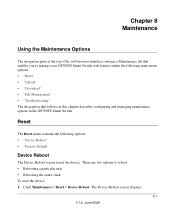
...8226; Rebooting a particular unit. • Rebooting the entire stack. There are two options to manage your GS700TS Smart Switch with features under the following options: • "Device Reboot" • "Factory Default" Device Reboot The Device Reboot screen resets the device. The Device Reboot screen displays: 8-1 V1.0, June 2009..." • "File Management" • "Troubleshooting" The description that follows in this chapter describes configuring and managing maintenance options in the GS700TS Smart Switch. Click Maintenance > Reset > Device Reboot. To reset the device: 1.
...8226; Rebooting a particular unit. • Rebooting the entire stack. There are two options to manage your GS700TS Smart Switch with features under the following options: • "Device Reboot" • "Factory Default" Device Reboot The Device Reboot screen resets the device. The Device Reboot screen displays: 8-1 V1.0, June 2009..." • "File Management" • "Troubleshooting" The description that follows in this chapter describes configuring and managing maintenance options in the GS700TS Smart Switch. Click Maintenance > Reset > Device Reboot. To reset the device: 1.
GS7xxTS User Manual
Page 221
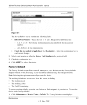
... button on the front panel of your device. GS700TS Smart Switch Software Administration Manual Figure 8-1 The Device Reboot screen contains the following fields: • Reboot Unit Number - Click APPLY to the factory defaults: 1. Reboots all stacking members. • Check this option automatically reboots the device. The Factory Default screen displays: Maintenance 8-2 v1.0, June 2009 Note: Selecting...
... button on the front panel of your device. GS700TS Smart Switch Software Administration Manual Figure 8-1 The Device Reboot screen contains the following fields: • Reboot Unit Number - Click APPLY to the factory defaults: 1. Reboots all stacking members. • Check this option automatically reboots the device. The Factory Default screen displays: Maintenance 8-2 v1.0, June 2009 Note: Selecting...
GS7xxTS User Manual
Page 222
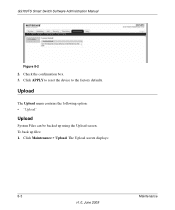
Click APPLY to reset the device to the factory defaults. To back up using the Upload screen. Click Maintenance > Upload. Check the confirmation box. 3. GS700TS Smart Switch Software Administration Manual Figure 8-2 2. Upload The Upload menu contains the following option: • "Upload" Upload System Files can be backed up files: 1. The Upload screen displays: 8-3 Maintenance v1.0, June 2009
Click APPLY to reset the device to the factory defaults. To back up using the Upload screen. Click Maintenance > Upload. Check the confirmation box. 3. GS700TS Smart Switch Software Administration Manual Figure 8-2 2. Upload The Upload menu contains the following option: • "Upload" Upload System Files can be backed up files: 1. The Upload screen displays: 8-3 Maintenance v1.0, June 2009

GS7xxTS User Manual
Page 230
...-negotiation Auto-negotiation Disabled Disabled DHCP enabled password 802.1q based VLAN Disabled Optimized for the NETGEAR Model GS700TS Smart Switch. You can always configure the switch to default settings by using the Factory Reset function from a Web browser. Table A-1. Chapter A Default Settings This appendix provides default settings for flow control, all ports set normal priority A-1 V1.0, June 2009
...-negotiation Auto-negotiation Disabled Disabled DHCP enabled password 802.1q based VLAN Disabled Optimized for the NETGEAR Model GS700TS Smart Switch. You can always configure the switch to default settings by using the Factory Reset function from a Web browser. Table A-1. Chapter A Default Settings This appendix provides default settings for flow control, all ports set normal priority A-1 V1.0, June 2009


