Shared access to the Internet for multiple VLANs - No routing
Page 3
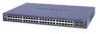
... Action/Edit: Click to make changes to the LAN port of the router. VLAN20 - 192.168.0.2/24 PC2 - Note: Additional IP addresses cannot be manually configured with subnet 255.255.255.0 Physical Setup 1x GS724TS Prosafe Smartswitch - Subnet Mask: IPv4 Subnet Mask. Delete: Deletes... IPs table. Firmware 3.1.0.1 2x Windows XP Computers (2 on each VLAN) 1 x DGFV338 Prosafe Firewall Router (Router firmware 3.4.0.19) Logical Setup GS724TS: Management IP on the secondary subnets must be configured in the DHCP server. Multi-Homing (extract from the DGFV338 Help page) Network...
... Action/Edit: Click to make changes to the LAN port of the router. VLAN20 - 192.168.0.2/24 PC2 - Note: Additional IP addresses cannot be manually configured with subnet 255.255.255.0 Physical Setup 1x GS724TS Prosafe Smartswitch - Subnet Mask: IPv4 Subnet Mask. Delete: Deletes... IPs table. Firmware 3.1.0.1 2x Windows XP Computers (2 on each VLAN) 1 x DGFV338 Prosafe Firewall Router (Router firmware 3.4.0.19) Logical Setup GS724TS: Management IP on the secondary subnets must be configured in the DHCP server. Multi-Homing (extract from the DGFV338 Help page) Network...
Shared access to the Internet for multiple VLANs - No routing
Page 4
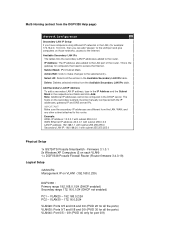
DGFV338 Primary LAN The Primary LAN settings can be defined on the GUI of the DGFV338 (Network Configuration, LAN Setup). If DHCP is required ensure that the correct Starting IP address and Ending IP address are configured including the DNSs settings.
DGFV338 Primary LAN The Primary LAN settings can be defined on the GUI of the DGFV338 (Network Configuration, LAN Setup). If DHCP is required ensure that the correct Starting IP address and Ending IP address are configured including the DNSs settings.
Shared access to the Internet for multiple VLANs - No routing
Page 5
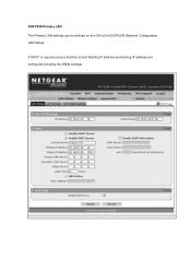
This can be used. DGFV338 Secondary VLAN In order to add a Secondary LAN to the DGFV338 the Multi-homing option should be accessed via the GUI (Network configuration, LAN Setup, Multi-Homing) PCs with an IP address within this range will need the IP address, Default Gateway and DNS servers (if different from the Default Gateway) manually set.
This can be used. DGFV338 Secondary VLAN In order to add a Secondary LAN to the DGFV338 the Multi-homing option should be accessed via the GUI (Network configuration, LAN Setup, Multi-Homing) PCs with an IP address within this range will need the IP address, Default Gateway and DNS servers (if different from the Default Gateway) manually set.
Shared access to the Internet for multiple VLANs - No routing
Page 6
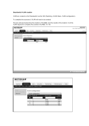
Smartswitch VLAN creation VLAN are created on the Smartswitch via the GUI (Switching, VLAN, Basic, VLAN configuration). The two pictures below show the creation of VLAN20, and the results of the creation of all the VLAN required to be created. To complete the scenarion 3 VLAN will need to complete the scenario (VLAN20, 30, 40)
Smartswitch VLAN creation VLAN are created on the Smartswitch via the GUI (Switching, VLAN, Basic, VLAN configuration). The two pictures below show the creation of VLAN20, and the results of the creation of all the VLAN required to be created. To complete the scenarion 3 VLAN will need to complete the scenario (VLAN20, 30, 40)
Shared access to the Internet for multiple VLANs - No routing
Page 8
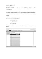
Assigning a PVID to a port The PVID (Port VLAN ID) is member of the VLAN IDs). In our scenario the following PVID will apply: Ports 0/5 - 0/6 (PVID 20) Ports 0/7 - 0/8 (PVID 30) Port 0/9 (PVID 40) The below pictures show how after clicking on apply (for all 3 VLANs PVID) we obtain the correct settings: It is important that the PVID matches the VLAN a port is assigned to multiple VLANs (in which case the PVID must still be set and be unique, but can match any of , unless such port belongs to each port via the GUI (Switching, VLAN, Advanced, Port PVID configuration).
Assigning a PVID to a port The PVID (Port VLAN ID) is member of the VLAN IDs). In our scenario the following PVID will apply: Ports 0/5 - 0/6 (PVID 20) Ports 0/7 - 0/8 (PVID 30) Port 0/9 (PVID 40) The below pictures show how after clicking on apply (for all 3 VLANs PVID) we obtain the correct settings: It is important that the PVID matches the VLAN a port is assigned to multiple VLANs (in which case the PVID must still be set and be unique, but can match any of , unless such port belongs to each port via the GUI (Switching, VLAN, Advanced, Port PVID configuration).
Shared access to the Internet for multiple VLANs - No routing
Page 10
...PC to ping the IP address of the Prosafe Firewall within the same IP subnet, and also connect to the Internet (assuming the DNS settings are correctly set via DHCP or manual configuration) Further notes The solution illustrated above allows multiple LANs to port 0/5 or 0/6 - Connect one PC ...with IP address in the 192.168.0.0/24 range to access the Internet but does not create Layer 3 separation, whilst Layer 2 VLAN separation is guaranteed by the switch. To obtain...
...PC to ping the IP address of the Prosafe Firewall within the same IP subnet, and also connect to the Internet (assuming the DNS settings are correctly set via DHCP or manual configuration) Further notes The solution illustrated above allows multiple LANs to port 0/5 or 0/6 - Connect one PC ...with IP address in the 192.168.0.0/24 range to access the Internet but does not create Layer 3 separation, whilst Layer 2 VLAN separation is guaranteed by the switch. To obtain...

GS7xxTS Hardware manual
Page 5
... 5: Installing an SFP GBIC Module 2-32 Step 6: Installing a Device 2-33 Step 7: Applying AC Power 2-34 Step 8: Managing the Switch through a Web Browser or the PC Utility for Initial Configuration ...2-35 Chapter 3 Physical Description Front and Back Panel Configuration 3-19 GS724TS Front and Back Panels 3-19 GS748TS Front and Back Panels 3-20 v v1.0, November 2007
... 5: Installing an SFP GBIC Module 2-32 Step 6: Installing a Device 2-33 Step 7: Applying AC Power 2-34 Step 8: Managing the Switch through a Web Browser or the PC Utility for Initial Configuration ...2-35 Chapter 3 Physical Description Front and Back Panel Configuration 3-19 GS724TS Front and Back Panels 3-19 GS748TS Front and Back Panels 3-20 v v1.0, November 2007
GS7xxTS Hardware manual
Page 6
... ...3-22 System LEDs ...3-22 Device Hardware Interfaces 3-23 RJ-45 Ports ...3-23 SFP GBIC Module 3-24 Factory Defaults Button 3-24 Appendix A Troubleshooting Troubleshooting Chart A-1 Additional Troubleshooting Suggestions A-2 Network Adapter Cards A-2 Configuration ...A-2 Switch Integrity ...A-2 Auto-negotiation ...A-3 Appendix B Technical Specifications Network Protocol and Standards Compatibility B-1 Management ...B-1 Interface ...B-1 LEDs ...B-1 Performance Specifications B-2 Power Supply ...B-2 Physical Specifications B-2 Environmental...
... ...3-22 System LEDs ...3-22 Device Hardware Interfaces 3-23 RJ-45 Ports ...3-23 SFP GBIC Module 3-24 Factory Defaults Button 3-24 Appendix A Troubleshooting Troubleshooting Chart A-1 Additional Troubleshooting Suggestions A-2 Network Adapter Cards A-2 Configuration ...A-2 Switch Integrity ...A-2 Auto-negotiation ...A-3 Appendix B Technical Specifications Network Protocol and Standards Compatibility B-1 Management ...B-1 Interface ...B-1 LEDs ...B-1 Performance Specifications B-2 Power Supply ...B-2 Physical Specifications B-2 Environmental...
GS7xxTS Hardware manual
Page 7
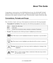
... of this notice may result in a malfunction or damage to highlight a procedure that will save time or resources. The NETGEAR® GS700TS Installation Manual describes how to take heed of the NETGEAR Smart Switch. ix v1.0, November 2007 This manual uses the following paragraphs: • Typographical Conventions. Tip: This format is used ...names, extensions, commands, IP addresses • Formats. Conventions, Formats and Scope The conventions, formats, and scope of importance or special interest. Failure to install, configure and troubleshoot the smart switch.
... of this notice may result in a malfunction or damage to highlight a procedure that will save time or resources. The NETGEAR® GS700TS Installation Manual describes how to take heed of the NETGEAR Smart Switch. ix v1.0, November 2007 This manual uses the following paragraphs: • Typographical Conventions. Tip: This format is used ...names, extensions, commands, IP addresses • Formats. Conventions, Formats and Scope The conventions, formats, and scope of importance or special interest. Failure to install, configure and troubleshoot the smart switch.
GS7xxTS Hardware manual
Page 11
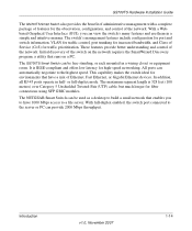
...control of Ethernet, Fast Ethernet, or Gigabit Ethernet devices. or full-duplex mode. GS700TS Hardware Installation Guide The GS700TS Smart Switch also provides the benefit of administrative ...configuration for port and switch information, VLAN for traffic control, port trunking for increased bandwidth, and Class of Service (CoS) for the observation, configuration, and control of the switch on a PC. Initial discovery of the network. The GS700TS Smart Switch can view the switch's many features and use them in a simple and intuitive manner. The NETGEAR Smart Switch...
...control of Ethernet, Fast Ethernet, or Gigabit Ethernet devices. or full-duplex mode. GS700TS Hardware Installation Guide The GS700TS Smart Switch also provides the benefit of administrative ...configuration for port and switch information, VLAN for traffic control, port trunking for increased bandwidth, and Class of Service (CoS) for the observation, configuration, and control of the switch on a PC. Initial discovery of the network. The GS700TS Smart Switch can view the switch's many features and use them in a simple and intuitive manner. The NETGEAR Smart Switch...
GS7xxTS Hardware manual
Page 14
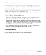
...The master and backup master are named as a general switch and does not run the stacking application. • Master Unit - The Stack Master provides a Single point of the NETGEAR Smart Switch 1-17 v1.0, November 2007 Introduction If a MasterBackup ...as the Stacking Master. Manages the Stack and is responsible for each stack members. Runs a slave version of the Switching Algorithm, which to control the resources of the following modes: • Stand-alone - A device can become a ...One of the slave units is downloaded separately for the configuration. • Master-Backup -
...The master and backup master are named as a general switch and does not run the stacking application. • Master Unit - The Stack Master provides a Single point of the NETGEAR Smart Switch 1-17 v1.0, November 2007 Introduction If a MasterBackup ...as the Stacking Master. Manages the Stack and is responsible for each stack members. Runs a slave version of the Switching Algorithm, which to control the resources of the following modes: • Stand-alone - A device can become a ...One of the slave units is downloaded separately for the configuration. • Master-Backup -

GS7xxTS Hardware manual
Page 16
... procedures for Initial Configuration Step 1: Preparing the Site Before installing the switch, ensure the operating...48.3-centimeter) EIA standard equipment rack that allows access to the front panel RJ-45 ports, the ability to view the front panel LEDs, and easy safe access access to the Switch... Step 5: Installing an SFP GBIC Module Step 6: Installing a Device Step 7: Applying AC Power Step 8: Managing the Switch through a Web Browser or the PC Utility for your NETGEAR Smart Switch. Table 2-1. Switch...
... procedures for Initial Configuration Step 1: Preparing the Site Before installing the switch, ensure the operating...48.3-centimeter) EIA standard equipment rack that allows access to the front panel RJ-45 ports, the ability to view the front panel LEDs, and easy safe access access to the Switch... Step 5: Installing an SFP GBIC Module Step 6: Installing a Device Step 7: Applying AC Power Step 8: Managing the Switch through a Web Browser or the PC Utility for your NETGEAR Smart Switch. Table 2-1. Switch...
GS7xxTS Hardware manual
Page 21
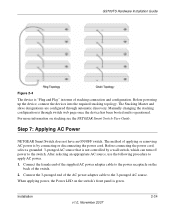
... of the supplied AC power adapter cable to the power receptacle on stacking see the NETGEAR Smart Switch User Guide. Step 7: Applying AC Power NETGEAR Smart Switch does not have an ON/OFF switch. Connect the female end of stacking connection and configuration. Before powering up the device, connect the devices into the required stacking topology. GS700TS Hardware...
... of the supplied AC power adapter cable to the power receptacle on stacking see the NETGEAR Smart Switch User Guide. Step 7: Applying AC Power NETGEAR Smart Switch does not have an ON/OFF switch. Connect the female end of stacking connection and configuration. Before powering up the device, connect the devices into the required stacking topology. GS700TS Hardware...
GS7xxTS Hardware manual
Page 22
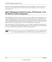
..., and also improves the efficiency of the network. Step 8: Managing the Switch through a Web Browser or the PC Utility for Initial Configuration The NETGEAR Smart Switch contains software for the first time, you to Appendix A "Troubleshooting". However, the management software enables you can use the ports without using a Web browser or a utility program called SmartWizard Discovery...
..., and also improves the efficiency of the network. Step 8: Managing the Switch through a Web Browser or the PC Utility for Initial Configuration The NETGEAR Smart Switch contains software for the first time, you to Appendix A "Troubleshooting". However, the management software enables you can use the ports without using a Web browser or a utility program called SmartWizard Discovery...

GS7xxTS Hardware manual
Page 23
... topics include: • GS724TS Front and Back Panels • GS748TS Front and Back Panels • LED Designations • Device Hardware Interfaces Front and Back Panel Configuration GS724TS Front and Back Panels The NETGEAR GS724TS Smart Switch is a 24-Port 10/100/1000 + 4-Port SFP Combo port switch, with each RJ45 ports capable of sensing the line speed and negotiating the...
... topics include: • GS724TS Front and Back Panels • GS748TS Front and Back Panels • LED Designations • Device Hardware Interfaces Front and Back Panel Configuration GS724TS Front and Back Panels The NETGEAR GS724TS Smart Switch is a 24-Port 10/100/1000 + 4-Port SFP Combo port switch, with each RJ45 ports capable of sensing the line speed and negotiating the...

GS7xxTS Hardware manual
Page 28
... SFP GBIC module. The module bay is a combo port, sharing a connection with the attached device, without requiring user intervention. Factory Defaults Button The Smart Switch has a Factory default button to enable clearing the current configuration and returning the device back to use crossover or straightthrough... Configures the RJ-45 port to enable communications with an RJ-45 port. For example, both connectors are plugged in at any given time. SFP GBIC Module The GBIC module bays accommodate standard SFP GBIC modules, such as the AGM731F, AGM732F, or AGM733 from NETGEAR,...
... SFP GBIC module. The module bay is a combo port, sharing a connection with the attached device, without requiring user intervention. Factory Defaults Button The Smart Switch has a Factory default button to enable clearing the current configuration and returning the device back to use crossover or straightthrough... Configures the RJ-45 port to enable communications with an RJ-45 port. For example, both connectors are plugged in at any given time. SFP GBIC Module The GBIC module bays accommodate standard SFP GBIC modules, such as the AGM731F, AGM732F, or AGM733 from NETGEAR,...
GS7xxTS Hardware manual
Page 30
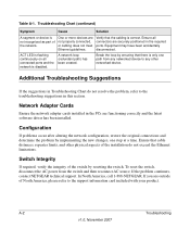
... connected, or cabling does not meet Ethernet guidelines. Ensure that the cabling is correct. In North America, call 1-888-NETGEAR. Troubleshooting Chart (continued) Symptom Cause Solution A segment or device is only one step at a time. One or more... suggestions in the required ports. A-2 Troubleshooting v1.0, November 2007 Table A-1. A network loop (redundant path) has been created. Configuration If problems occur after altering the network configuration, restore the original connections and determine the problem by resetting the switch. If you are securely...
... connected, or cabling does not meet Ethernet guidelines. Ensure that the cabling is correct. In North America, call 1-888-NETGEAR. Troubleshooting Chart (continued) Symptom Cause Solution A segment or device is only one step at a time. One or more... suggestions in the required ports. A-2 Troubleshooting v1.0, November 2007 Table A-1. A network loop (redundant path) has been created. Configuration If problems occur after altering the network configuration, restore the original connections and determine the problem by resetting the switch. If you are securely...

GS7xxTS Quick Install Guide
Page 1
..., configure the switch IP address before connecting it to your network. 4. Now, Configure the Switch with an RJ-45 connector to connect. Figure 3 The Smartwizard Discovery utility finds the switch and displays its IP address. First, Verify Package Contents • NETGEAR Smart Switch &#...absence of a DHCP server, the switch defaults to 192.168.0.239 for installing the switch in your network. Then, use the Smartwizard Discovery utility to find your smart switch. )NSTALLATION'UIDE GS700TS (724TS, 748TS) Series Gigabit Stackable Smart Switch Start Here Follow these instructions to...
..., configure the switch IP address before connecting it to your network. 4. Now, Configure the Switch with an RJ-45 connector to connect. Figure 3 The Smartwizard Discovery utility finds the switch and displays its IP address. First, Verify Package Contents • NETGEAR Smart Switch &#...absence of a DHCP server, the switch defaults to 192.168.0.239 for installing the switch in your network. Then, use the Smartwizard Discovery utility to find your smart switch. )NSTALLATION'UIDE GS700TS (724TS, 748TS) Series Gigabit Stackable Smart Switch Start Here Follow these instructions to...
GS7xxTS Quick Install Guide
Page 2
...NETGEAR and the NETGEAR logo are multiple smart switches in your PC and smart switch in screen. Go to change without notice. in accordance with the European Union Directive 2002/96 on computer connected to the smart switch with this sequence. Information is required before you may have selected the correct switch to configure...label of your switch. If there are registered trademarks of your jurisdiction implementing the WEEE Directive. © 2007 by NETGEAR, Inc. For help with a securely plugged in Ethernet cable, the corresponding smart switch LAN port status light will ...
...NETGEAR and the NETGEAR logo are multiple smart switches in your PC and smart switch in screen. Go to change without notice. in accordance with the European Union Directive 2002/96 on computer connected to the smart switch with this sequence. Information is required before you may have selected the correct switch to configure...label of your switch. If there are registered trademarks of your jurisdiction implementing the WEEE Directive. © 2007 by NETGEAR, Inc. For help with a securely plugged in Ethernet cable, the corresponding smart switch LAN port status light will ...

GS7xxTS User Manual
Page 3
EU Statement of Compliance The NETGEAR GS700TS Gigabit Stackable Smart Switch is verified by one or more of the following measures: • Reorient or relocate the receiving antenna. • Increase the separation between the equipment ... on the Support Information Card that was included with installing and configuring your NETGEAR system or for help. In a domestic environment, this product may be returned to your switch. • Email Technical Support at the uniform resource locator (URL) http:// www.NETGEAR.com. Compliance is compliant with the following EU Council Directives: ...
EU Statement of Compliance The NETGEAR GS700TS Gigabit Stackable Smart Switch is verified by one or more of the following measures: • Reorient or relocate the receiving antenna. • Increase the separation between the equipment ... on the Support Information Card that was included with installing and configuring your NETGEAR system or for help. In a domestic environment, this product may be returned to your switch. • Email Technical Support at the uniform resource locator (URL) http:// www.NETGEAR.com. Compliance is compliant with the following EU Council Directives: ...


