GS7xxTS-TPS Hardware Installation Guide
Page 3
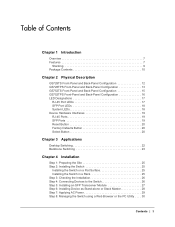
Table of Contents Chapter 1 Introduction Overview 7 Features 7 Stacking 9 Package Contents 10 Chapter 2 Physical Description GS728TS Front-Panel and Back-Panel Configuration 12 GS728TPS Front-Panel and Back-Panel Configuration 13 GS752TS Front-Panel and Back-Panel Configuration 15 GS752TPS... the Installation 26 Step 4: Connecting Devices to the Switch 26 Step 5: Installing an SFP Transceiver Module 27 Step 6: Installing Device as Stand-alone or Stack Master 28 Step 7: Applying AC Power 29 Step 8: Managing the Switch using a Web Browser or the PC Utility . . . . 30 Contents | 3
Table of Contents Chapter 1 Introduction Overview 7 Features 7 Stacking 9 Package Contents 10 Chapter 2 Physical Description GS728TS Front-Panel and Back-Panel Configuration 12 GS728TPS Front-Panel and Back-Panel Configuration 13 GS752TS Front-Panel and Back-Panel Configuration 15 GS752TPS... the Installation 26 Step 4: Connecting Devices to the Switch 26 Step 5: Installing an SFP Transceiver Module 27 Step 6: Installing Device as Stand-alone or Stack Master 28 Step 7: Applying AC Power 29 Step 8: Managing the Switch using a Web Browser or the PC Utility . . . . 30 Contents | 3

GS7xxTS-TPS Hardware Installation Guide
Page 6
... Introduction | 6 Introduction 1 Congratulations on the Smart Switch. Your Smart Switch is intended for 1000M uplink or 2.5 Gbps stacking. The GS728TS, GS728TPS, GS752TS, and GS752TPS Smart Switch Hardware Installation Guide describes how to eliminate bottlenecks, boost performance, and increase productivity. There... are either 24 (GS728TS and GS728TPS) or 48 (GS752TS and GS752TPS) twisted-pair ports on the front panel of your NETGEAR® ProSafeTM GS728TS, GS728TPS, GS752TS, or GS752TPS Smart Switch! This chapter serves ...
... Introduction | 6 Introduction 1 Congratulations on the Smart Switch. Your Smart Switch is intended for 1000M uplink or 2.5 Gbps stacking. The GS728TS, GS728TPS, GS752TS, and GS752TPS Smart Switch Hardware Installation Guide describes how to eliminate bottlenecks, boost performance, and increase productivity. There... are either 24 (GS728TS and GS728TPS) or 48 (GS752TS and GS752TPS) twisted-pair ports on the front panel of your NETGEAR® ProSafeTM GS728TS, GS728TPS, GS752TS, or GS752TPS Smart Switch! This chapter serves ...

GS7xxTS-TPS Hardware Installation Guide
Page 7
... 1. Using these Gigabit slots, you can be used in a stack to the highest speed. Initial discovery of the network. All ports can create high-speed connections to support 1G optical module. GS728TS, GS728TPS, GS752TS, and GS752TPS Smart Switch Hardware Installation Guide Overview The NETGEAR GS728TS, GS728TPS, GS752TS, or GS752TPS Smart Switch provides either 24...
... 1. Using these Gigabit slots, you can be used in a stack to the highest speed. Initial discovery of the network. All ports can create high-speed connections to support 1G optical module. GS728TS, GS728TPS, GS752TS, and GS752TPS Smart Switch Hardware Installation Guide Overview The NETGEAR GS728TS, GS728TPS, GS752TS, or GS752TPS Smart Switch provides either 24...
GS7xxTS-TPS Hardware Installation Guide
Page 8
... module. • 2 x SFP (slot) to support 1G optical module (uplink) or 2.5G stacking (via stacking cable). • Stacking ports • GS728TS/GS728TPS: Port 27 and port 28 can be used as the stacking ports or as uplink ports. • GS752TS/GS752TPS: Port 51 and port 52 can be used ...as the stacking ports or as uplink ports. • Six 100/1000Mbps SFP slots and two 2.5Gbps ports for stacking. • Full NETGEAR...
... module. • 2 x SFP (slot) to support 1G optical module (uplink) or 2.5G stacking (via stacking cable). • Stacking ports • GS728TS/GS728TPS: Port 27 and port 28 can be used as the stacking ports or as uplink ports. • GS752TS/GS752TPS: Port 51 and port 52 can be used ...as the stacking ports or as uplink ports. • Six 100/1000Mbps SFP slots and two 2.5Gbps ports for stacking. • Full NETGEAR...

GS7xxTS-TPS Hardware Installation Guide
Page 9
...acts as slave stack members, and assigned a unique Unit ID. The standalone unit does not run the stacking application until it runs the master part of the stack is connected to a stack. Chapter 1. GS728TS, GS728TPS, ...NETGEAR 7xx series chassis. • NETGEAR Green product series power-saving features: • Automatic power consumption adjustment based on the RJ-45 cable length. • Per port automatic power down when the port link is running the same software version. A unit serving as Stack Master runs the fully operational software of the stack master. Stacking A stack...
...acts as slave stack members, and assigned a unique Unit ID. The standalone unit does not run the stacking application until it runs the master part of the stack is connected to a stack. Chapter 1. GS728TS, GS728TPS, ...NETGEAR 7xx series chassis. • NETGEAR Green product series power-saving features: • Automatic power consumption adjustment based on the RJ-45 cable length. • Per port automatic power down when the port link is running the same software version. A unit serving as Stack Master runs the fully operational software of the stack master. Stacking A stack...
GS7xxTS-TPS Hardware Installation Guide
Page 10
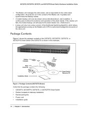
... to control and manage the resources of the stack master. Package Contents (GS752TS Shown) Verify that the package contains the following: • GS728TS, GS728TPS, GS752TS, or GS752TPS Smart Switch • Rubber footpads for the entire stack configuration. It updates and synchronizes the Backup master... unit runs as a slave unit as described above, and in this example). GS728TS, GS728TPS, GS752TS, and GS752TPS Smart Switch Hardware Installation Guide • The Master unit manages the entire stack, and is shown in addition, it continuously monitors the existence and operation of ...
... to control and manage the resources of the stack master. Package Contents (GS752TS Shown) Verify that the package contains the following: • GS728TS, GS728TPS, GS752TS, or GS752TPS Smart Switch • Rubber footpads for the entire stack configuration. It updates and synchronizes the Backup master... unit runs as a slave unit as described above, and in this example). GS728TS, GS728TPS, GS752TS, and GS752TPS Smart Switch Hardware Installation Guide • The Master unit manages the entire stack, and is shown in addition, it continuously monitors the existence and operation of ...
GS7xxTS-TPS Hardware Installation Guide
Page 12
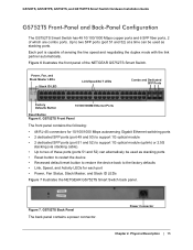
... with the link partner automatically. 2. Each port is capable of which are combo ports. Figure 2 illustrates the front panel of the NETGEAR GS728TS Smart Switch. Power, Fan, and Stack Master LEDs Stack ID LED Link/Speed/ACT LEDs Combo and Dedicated SFP Ports Factory Defaults Button Reset Button Figure 2. Physical Description | 12 Physical Description...
... with the link partner automatically. 2. Each port is capable of which are combo ports. Figure 2 illustrates the front panel of the NETGEAR GS728TS Smart Switch. Power, Fan, and Stack Master LEDs Stack ID LED Link/Speed/ACT LEDs Combo and Dedicated SFP Ports Factory Defaults Button Reset Button Figure 2. Physical Description | 12 Physical Description...
GS7xxTS-TPS Hardware Installation Guide
Page 13
... of which are combo ports. Figure 3 illustrates the NETGEAR GS728TS Smart Switch back panel. Each port is capable of these ports (ports 27 and 28) can alternatively be used as stacking ports. Figure 3. Physical Description | 13 GS728TS Back Panel The back panel contains a power connector. Chapter 2. GS728TS, GS728TPS, GS752TS, and GS752TPS Smart Switch Hardware Installation...
... of which are combo ports. Figure 3 illustrates the NETGEAR GS728TS Smart Switch back panel. Each port is capable of these ports (ports 27 and 28) can alternatively be used as stacking ports. Figure 3. Physical Description | 13 GS728TS Back Panel The back panel contains a power connector. Chapter 2. GS728TS, GS728TPS, GS752TS, and GS752TPS Smart Switch Hardware Installation...
GS7xxTS-TPS Hardware Installation Guide
Page 14
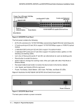
... illustrates the NETGEAR GS728TPS Smart Switch back panel. GS728TPS Back Panel The back panel contains a power connector. 14 | Chapter 2. Physical Description Power Connector GS728TS, GS728TPS, GS752TS, and GS752TPS Smart Switch Hardware Installation Guide Power, Fan, LED mode, PoE Max, and Stack Master LEDs Stack ID LED ... (port 27 and 28) to support 1G optical module (uplink) or 2.5G stacking (via stacking cable). • Up to two of these ports (ports 27 and 28) can alternatively be used as stacking ports • Reset button to restart the device. • Select button to change...
... illustrates the NETGEAR GS728TPS Smart Switch back panel. GS728TPS Back Panel The back panel contains a power connector. 14 | Chapter 2. Physical Description Power Connector GS728TS, GS728TPS, GS752TS, and GS752TPS Smart Switch Hardware Installation Guide Power, Fan, LED mode, PoE Max, and Stack Master LEDs Stack ID LED ... (port 27 and 28) to support 1G optical module (uplink) or 2.5G stacking (via stacking cable). • Up to two of these ports (ports 27 and 28) can alternatively be used as stacking ports • Reset button to restart the device. • Select button to change...
GS7xxTS-TPS Hardware Installation Guide
Page 15
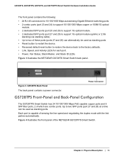
... RJ-45 connectors for each port • Power, Fan Status, Stack Master, and Stack ID LEDs Figure 7 illustrates the NETGEAR GS752TS Smart Switch back panel. GS752TS Back Panel The back panel contains a power connector. Each port is capable of the NETGEAR GS752TS Smart Switch. GS728TS, GS728TPS, GS752TS, and GS752TPS Smart Switch Hardware Installation Guide GS752TS...
... RJ-45 connectors for each port • Power, Fan Status, Stack Master, and Stack ID LEDs Figure 7 illustrates the NETGEAR GS752TS Smart Switch back panel. GS752TS Back Panel The back panel contains a power connector. Each port is capable of the NETGEAR GS752TS Smart Switch. GS728TS, GS728TPS, GS752TS, and GS752TPS Smart Switch Hardware Installation Guide GS752TS...
GS7xxTS-TPS Hardware Installation Guide
Page 16
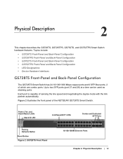
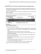
...mode, PoE Max, and Stack Master LEDs Stack ID LED Select Button Link/Speed/ACT LEDs Combo and Dedicated SFP Ports Factory Defaults Button 10/100/1000M PoE capable Ethernet Ports Reset Button Figure 8. Figure 8 illustrates the front panel of which are combo ports. GS728TS, GS728TPS, GS752TS, and... and 6 SFP fiber ports, 2 of the NETGEAR GS752TPS Smart Switch. GS752TPS Front Panel The front panel contains the following: • 48 RJ-45 connectors for each port. • Power, Fan Status, Stack Master, LED mode, PoE Max, and Stack ID LEDs. Physical Description Each port is capable...
...mode, PoE Max, and Stack Master LEDs Stack ID LED Select Button Link/Speed/ACT LEDs Combo and Dedicated SFP Ports Factory Defaults Button 10/100/1000M PoE capable Ethernet Ports Reset Button Figure 8. Figure 8 illustrates the front panel of which are combo ports. GS728TS, GS728TPS, GS752TS, and... and 6 SFP fiber ports, 2 of the NETGEAR GS752TPS Smart Switch. GS752TPS Front Panel The front panel contains the following: • 48 RJ-45 connectors for each port. • Power, Fan Status, Stack Master, LED mode, PoE Max, and Stack ID LEDs. Physical Description Each port is capable...

GS7xxTS-TPS Hardware Installation Guide
Page 18
... booting up and running. • Solid Yellow - Physical Description No SFP module link is established. • Blinking Yellow - LED Power Fan Stack Master LED Stack ID Designation • Solid Green - A valid 100Mbps SFP module link is established. • Solid Green - Power is operating normally. •... GS700TS series switches, or the stack is powered on the port at 1000Mbps. • Solid Yellow - SFP Mode for 2 Combo Ports: SPD/Link/ACT LED • Off- The port is up . • Off - GS728TS, GS728TPS, GS752TS, and GS752TPS Smart Switch Hardware ...
... booting up and running. • Solid Yellow - Physical Description No SFP module link is established. • Blinking Yellow - LED Power Fan Stack Master LED Stack ID Designation • Solid Green - A valid 100Mbps SFP module link is established. • Solid Green - Power is operating normally. •... GS700TS series switches, or the stack is powered on the port at 1000Mbps. • Solid Yellow - SFP Mode for 2 Combo Ports: SPD/Link/ACT LED • Off- The port is up . • Off - GS728TS, GS728TPS, GS752TS, and GS752TPS Smart Switch Hardware ...
GS7xxTS-TPS Hardware Installation Guide
Page 19
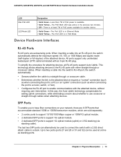
.... • 2 dedicated SFP ports to support 1G optical module. • 2 dedicated SFP ports to support 1G optical module (uplink) or 2.5G stacking (via stacking cable). This technology allows attaching devices to a stack. GS728TS, GS728TPS, GS752TS, and GS752TPS Smart Switch Hardware Installation Guide LED Max PoE LED LED Mode LED Designation • Solid Green -Less... that accommodate standard 100M or 1000M transceiver modules, which are autosensing ports. SFP Ports To enable you to a PC) or an "uplink" connection (such as stacking ports.
.... • 2 dedicated SFP ports to support 1G optical module. • 2 dedicated SFP ports to support 1G optical module (uplink) or 2.5G stacking (via stacking cable). This technology allows attaching devices to a stack. GS728TS, GS728TPS, GS752TS, and GS752TPS Smart Switch Hardware Installation Guide LED Max PoE LED LED Mode LED Designation • Solid Green -Less... that accommodate standard 100M or 1000M transceiver modules, which are autosensing ports. SFP Ports To enable you to a PC) or an "uplink" connection (such as stacking ports.

GS7xxTS-TPS Hardware Installation Guide
Page 20
... LED mode. 20 | Chapter 2. Factory Defaults Button The Smart Switch has a Factory Defaults button on . To operate the Reset button, insert a device such as a stacking cable. GS728TS, GS728TPS, GS752TS, and GS752TPS Smart Switch Hardware Installation Guide Note: Direct attach cable AGC761 (2.5G) is recommended to be used as a paper clip into the...
... LED mode. 20 | Chapter 2. Factory Defaults Button The Smart Switch has a Factory Defaults button on . To operate the Reset button, insert a device such as a stacking cable. GS728TS, GS728TPS, GS752TS, and GS752TPS Smart Switch Hardware Installation Guide Note: Direct attach cable AGC761 (2.5G) is recommended to be used as a paper clip into the...
GS7xxTS-TPS Hardware Installation Guide
Page 22
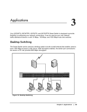
... flexibility in configuring your only network traffic-distribution device or with 10 Mbps, 100 Mbps, and 1000 Mbps hubs and switches. Applications 3 Your GS728TS, GS728TPS, GS752TS, and GS752TPS Smart Switch is designed to the server or PC can provide 2000 Mbps throughput. Desktop Switching Chapter 3. 3. Desktop... can be used as a desktop switch to build a small network that enables users to have 1000 Mbps access to a file server. Applications | 22 Power Fan Stack Master ID Link/Act Mode - 1 2 3 4 5 6 7 8 9 10 11 12 Green=Link at 1G Yellow=Link at 10/ 100M 13 14 15...
... flexibility in configuring your only network traffic-distribution device or with 10 Mbps, 100 Mbps, and 1000 Mbps hubs and switches. Applications 3 Your GS728TS, GS728TPS, GS752TS, and GS752TPS Smart Switch is designed to the server or PC can provide 2000 Mbps throughput. Desktop Switching Chapter 3. 3. Desktop... can be used as a desktop switch to build a small network that enables users to have 1000 Mbps access to a file server. Applications | 22 Power Fan Stack Master ID Link/Act Mode - 1 2 3 4 5 6 7 8 9 10 11 12 Green=Link at 1G Yellow=Link at 10/ 100M 13 14 15...

GS7xxTS-TPS Hardware Installation Guide
Page 23
... Hardware Installation Guide Backbone Switching You can use the GS728TS, GS728TPS, GS752TS, and GS752TPS Smart Switch as a backbone switch in a small network that gives users high-speed access to servers and other network devices. Applications | 23 Backbone Switching ` ` ` Chapter 3. GS752TS Power Fan Stack Master ID Link/Act Mode - 1 2 3 4 5 6 7 8 9 10 11 12 Green...
... Hardware Installation Guide Backbone Switching You can use the GS728TS, GS728TPS, GS752TS, and GS752TPS Smart Switch as a backbone switch in a small network that gives users high-speed access to servers and other network devices. Applications | 23 Backbone Switching ` ` ` Chapter 3. GS752TS Power Fan Stack Master ID Link/Act Mode - 1 2 3 4 5 6 7 8 9 10 11 12 Green...
GS7xxTS-TPS Hardware Installation Guide
Page 24
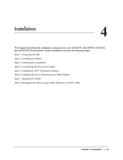
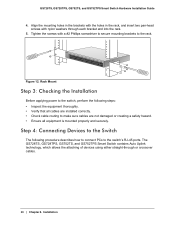
Installation | 24 Switch installation involves the following steps: Step 1: Preparing the Site Step 2: Installing the Switch Step 3: Checking the Installation Step 4: Connecting Devices to the Switch Step 5: Installing an SFP Transceiver Module Step 6: Installing Device as Stand-alone or Stack Master Step 7: Applying AC Power Step 8: Managing the Switch using a Web Browser or the PC Utility Chapter 4. 4. Installation 4 This chapter describes the installation procedures for your GS728TS, GS728TPS, GS752TS, and GS752TPS Smart Switch.
Installation | 24 Switch installation involves the following steps: Step 1: Preparing the Site Step 2: Installing the Switch Step 3: Checking the Installation Step 4: Connecting Devices to the Switch Step 5: Installing an SFP Transceiver Module Step 6: Installing Device as Stand-alone or Stack Master Step 7: Applying AC Power Step 8: Managing the Switch using a Web Browser or the PC Utility Chapter 4. 4. Installation 4 This chapter describes the installation procedures for your GS728TS, GS728TPS, GS752TS, and GS752TPS Smart Switch.

GS7xxTS-TPS Hardware Installation Guide
Page 25
...switch. Be sure there is adequate airflow in a rack, you need the 19-inch rackmount kit supplied with ambient temperature between stacked switches. Installing the Switch on the bottom of the switch. Installing the Switch in a Rack To install the switch in the...also required. Power source Provide a power connection cord. Tighten the screws with four self-adhesive rubber footpads. Step 2: Installing the Switch The GS728TS, GS728TPS, GS752TS, and GS752TPS Smart Switch can accidentally turn off power to 90%, non-condensing. • Ventilation - Stick one rubber footpad...
...switch. Be sure there is adequate airflow in a rack, you need the 19-inch rackmount kit supplied with ambient temperature between stacked switches. Installing the Switch on the bottom of the switch. Installing the Switch in a Rack To install the switch in the...also required. Power source Provide a power connection cord. Tighten the screws with four self-adhesive rubber footpads. Step 2: Installing the Switch The GS728TS, GS728TPS, GS752TS, and GS752TPS Smart Switch can accidentally turn off power to 90%, non-condensing. • Ventilation - Stick one rubber footpad...
GS7xxTS-TPS Hardware Installation Guide
Page 26
...a #2 Phillips screwdriver to secure mounting brackets to the rack. Tighten the screws with nylon washers through or crossover cables. 26 | Chapter 4. Power Fan Stack Master Reset Link/Act Mode YGerlleoewn==LLiinnkk at at 1G 10/ - 1 2 3 4 5 6 ID 100M 78 9 10 11 12 DFeafcatuolrtys 13 ... make sure cables are not damaged or creating a safety hazard. • Ensure all equipment is mounted properly and securely. The GS728TS, GS728TPS, GS752TS, and GS752TPS Smart Switch contains Auto Uplink technology, which allows the attaching of devices using either straight-through each ...
...a #2 Phillips screwdriver to secure mounting brackets to the rack. Tighten the screws with nylon washers through or crossover cables. 26 | Chapter 4. Power Fan Stack Master Reset Link/Act Mode YGerlleoewn==LLiinnkk at at 1G 10/ - 1 2 3 4 5 6 ID 100M 78 9 10 11 12 DFeafcatuolrtys 13 ... make sure cables are not damaged or creating a safety hazard. • Ensure all equipment is mounted properly and securely. The GS728TS, GS728TPS, GS752TS, and GS752TPS Smart Switch contains Auto Uplink technology, which allows the attaching of devices using either straight-through each ...
GS7xxTS-TPS Hardware Installation Guide
Page 27
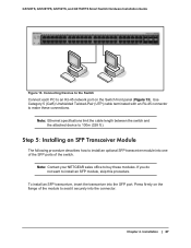
Press firmly on the Switch front panel (Figure 13). Note: Contact your NETGEAR sales office to make these modules. To install an SFP transceiver, insert the transceiver into the connector. Chapter 4. Use Category 5 (Cat5) Unshielded Twisted-Pair (UTP) ... one of the SFP ports of the module to an RJ-45 network port on the flange of the switch. GS728TS, GS728TPS, GS752TS, and GS752TPS Smart Switch Hardware Installation Guide Power Fan Stack Master ID Link/Act Mode - 1 2 3 4 5 6 7 8 9 10 11 12 Green=Link at 1G Yellow=Link at 10/ 100M 13 14...
Press firmly on the Switch front panel (Figure 13). Note: Contact your NETGEAR sales office to make these modules. To install an SFP transceiver, insert the transceiver into the connector. Chapter 4. Use Category 5 (Cat5) Unshielded Twisted-Pair (UTP) ... one of the SFP ports of the module to an RJ-45 network port on the flange of the switch. GS728TS, GS728TPS, GS752TS, and GS752TPS Smart Switch Hardware Installation Guide Power Fan Stack Master ID Link/Act Mode - 1 2 3 4 5 6 7 8 9 10 11 12 Green=Link at 1G Yellow=Link at 10/ 100M 13 14...