Hardware Installation Guide
Page 5
... Configuration 10 GS748T Back Panel Configuration 10 LED Designations 11 Port LEDs 11 System LEDs 12 Device Hardware Interfaces 13 RJ-45 Ports 13 SFP GBIC Module 13 Factory Defaults Button 13 Chapter 3 Applications Desktop Switching 15 Backbone Switching 15 Chapter 4 Installation Step 1: Prepare the Site...Surface 19 Install the Switch in a Rack 19 Step 3: Check the Installation 20 Step 4: Connect Devices to the Switch 21 Step 5: Install an SFP GBIC Module 22 Step 6: Apply AC Power 23 Step 7: Manage the Switch using a Web Browser or the Smart Control Center Utility 24 Appendix ...
... Configuration 10 GS748T Back Panel Configuration 10 LED Designations 11 Port LEDs 11 System LEDs 12 Device Hardware Interfaces 13 RJ-45 Ports 13 SFP GBIC Module 13 Factory Defaults Button 13 Chapter 3 Applications Desktop Switching 15 Backbone Switching 15 Chapter 4 Installation Step 1: Prepare the Site...Surface 19 Install the Switch in a Rack 19 Step 3: Check the Installation 20 Step 4: Connect Devices to the Switch 21 Step 5: Install an SFP GBIC Module 22 Step 6: Apply AC Power 23 Step 7: Manage the Switch using a Web Browser or the Smart Control Center Utility 24 Appendix ...
Hardware Installation Guide
Page 7
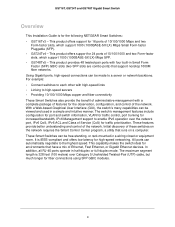
The front panel also has 2 SFP ports that support nonstop 10/100/1000 networks. Introduction ...-art, high-performance, IEEE-compliant network solution designed for readers with intermediate computer and Internet skills. The GS716Tv3, GS724Tv4, GS748Tv5 Cost Down Hardware Installation Guide describes how to the Smart Switch and provides the following information: •... Overview • Features • Package Contents 3 This NETGEAR Smart Switch is shipped ready for use out of the GS716T,GS724T,GS748T Series Smart Switch. This chapter...
The front panel also has 2 SFP ports that support nonstop 10/100/1000 networks. Introduction ...-art, high-performance, IEEE-compliant network solution designed for readers with intermediate computer and Internet skills. The GS716Tv3, GS724Tv4, GS748Tv5 Cost Down Hardware Installation Guide describes how to the Smart Switch and provides the following information: •... Overview • Features • Package Contents 3 This NETGEAR Smart Switch is shipped ready for use out of the GS716T,GS724T,GS748T Series Smart Switch. This chapter...
Hardware Installation Guide
Page 8
...configuration, and control of 10/100/1000 and two Form-factor slots, which support 1000 (1000BASE-SX/LX) Mbps Small Form-factor Pluggable (SFP). • GS724Tv4 - For example: • Connect switches to each other with high-speed links • Linking to enable IPv6 operation over Category 5 ... viewed and used in a wiring closet or equipment room. The maximum segment length is IEEE-compliant and offers low latency for the following NETGEAR Smart Switches: • GS716Tv3 - These Smart Switches can be free-standing, or rack mounted in a simple and intuitive manner. It ...
...configuration, and control of 10/100/1000 and two Form-factor slots, which support 1000 (1000BASE-SX/LX) Mbps Small Form-factor Pluggable (SFP). • GS724Tv4 - For example: • Connect switches to each other with high-speed links • Linking to enable IPv6 operation over Category 5 ... viewed and used in a wiring closet or equipment room. The maximum segment length is IEEE-compliant and offers low latency for the following NETGEAR Smart Switches: • GS716Tv3 - These Smart Switches can be free-standing, or rack mounted in a simple and intuitive manner. It ...
Hardware Installation Guide
Page 9
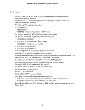
... Features • GS716Tv3/GS724Tv4 has 16/24 10/100/1000Mbps ethernet copper ports and 2 dedicated 1000Mbps fiber ports. • GS748Tv5 has 48 10/100/1000Mbps ethernet copper port, 2 Combo ports and 2 dedicated 1000Mbps fiber ports. • The following SFP types are supported: •...; 1000BASE-SX • 1000BASE-LX • 100BASE-FX (for combo ports on GS748T only) • The devices support full NETGEAR Smart Switch functionality. • The devices provide full compatibility with ...
... Features • GS716Tv3/GS724Tv4 has 16/24 10/100/1000Mbps ethernet copper ports and 2 dedicated 1000Mbps fiber ports. • GS748Tv5 has 48 10/100/1000Mbps ethernet copper port, 2 Combo ports and 2 dedicated 1000Mbps fiber ports. • The following SFP types are supported: •...; 1000BASE-SX • 1000BASE-LX • 100BASE-FX (for combo ports on GS748T only) • The devices support full NETGEAR Smart Switch functionality. • The devices provide full compatibility with ...
Hardware Installation Guide
Page 12
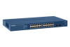
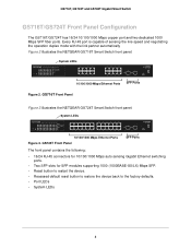
...Every RJ-45 port is capable of sensing the line speed and negotiating the operation duplex mode with the link partner automatically Figure 2 illustrates the NETGEAR GS716T Smart Switch front panel: Reset PWR System LEDs ProSafe 16 Port 10/100/1000Mbps Smart Switch Link/ACT SPD Green(1000M) Yellow(100M) ...FDX Link/ACT SPD FDX 10/100/1000 Mbps Ethernet Ports SFP Ports Figure 2. GS716T, GS724T and GS748T Gigabit Smart Switch GS716T/GS724T Front Panel Configuration The GS716T/GS724T has 16/24 10/100/1000 Mbps...
...Every RJ-45 port is capable of sensing the line speed and negotiating the operation duplex mode with the link partner automatically Figure 2 illustrates the NETGEAR GS716T Smart Switch front panel: Reset PWR System LEDs ProSafe 16 Port 10/100/1000Mbps Smart Switch Link/ACT SPD Green(1000M) Yellow(100M) ...FDX Link/ACT SPD FDX 10/100/1000 Mbps Ethernet Ports SFP Ports Figure 2. GS716T, GS724T and GS748T Gigabit Smart Switch GS716T/GS724T Front Panel Configuration The GS716T/GS724T has 16/24 10/100/1000 Mbps...
Hardware Installation Guide
Page 14
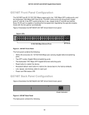
... ports, and two dedicated 1000 Mbps SFP fiber ports. The SFP combo ports are inactive. If the SFP combo ports are in use, copper ports 47 and 48 are shared with the link partner automatically Figure 5 illustrates the NETGEAR GS748T Smart Switch front panel: System LEDs 10/100/1000 Mbps Ethernet Ports SFP Ports Figure 5.
... ports, and two dedicated 1000 Mbps SFP fiber ports. The SFP combo ports are inactive. If the SFP combo ports are in use, copper ports 47 and 48 are shared with the link partner automatically Figure 5 illustrates the NETGEAR GS748T Smart Switch front panel: System LEDs 10/100/1000 Mbps Ethernet Ports SFP Ports Figure 5.
Hardware Installation Guide
Page 15
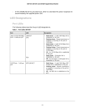
.../100 Mbps. • Off - Port LEDs GS748T Port LED 16/24-10/100/1000 Mbps LINK/ACT Ports - 3 LEDs per port SPD FDX 2 SFP Ports - 1 LED per SFP LINK/ACT port Designation • Solid Green - LED Designations Port LEDs The following tables describe the port LED designations. Table 1. Packets transmission or reception... established on the port. • Flashing Green - No full-duplex or half-duplex link is established on the port. • Flashing Green - A valid 1000 Mbps SFP module link is established on the port. • Solid Green -
.../100 Mbps. • Off - Port LEDs GS748T Port LED 16/24-10/100/1000 Mbps LINK/ACT Ports - 3 LEDs per port SPD FDX 2 SFP Ports - 1 LED per SFP LINK/ACT port Designation • Solid Green - LED Designations Port LEDs The following tables describe the port LED designations. Table 1. Packets transmission or reception... established on the port. • Flashing Green - No full-duplex or half-duplex link is established on the port. • Flashing Green - A valid 1000 Mbps SFP module link is established on the port. • Solid Green -

Hardware Installation Guide
Page 16
...off . • Off - Port LEDs GS748T Port 48 10/100/1000 Mbps Copper ports LED LINK/ACT/SPD Combo SFP port 47~48 LINK/ACT/SPD SFP port 49~50 LINK/ACT/SPD Designation • Off - A valid 1000 Mbps link is established • Solid Green - No... Designation • Solid Green - Power is supplied to off . • Off - The fan has experienced a fail. • Off - A valid 1000 Mbps SFP module link is disconnected. • Solid yellow - Power is established. • Blinking Green - GS716T, GS724T and GS748T Gigabit Smart Switch Table 2. System LEDs The ...
...off . • Off - Port LEDs GS748T Port 48 10/100/1000 Mbps Copper ports LED LINK/ACT/SPD Combo SFP port 47~48 LINK/ACT/SPD SFP port 49~50 LINK/ACT/SPD Designation • Off - A valid 1000 Mbps link is established • Solid Green - No... Designation • Solid Green - Power is supplied to off . • Off - The fan has experienced a fail. • Off - A valid 1000 Mbps SFP module link is disconnected. • Solid yellow - Power is established. • Blinking Green - GS716T, GS724T and GS748T Gigabit Smart Switch Table 2. System LEDs The ...
Hardware Installation Guide
Page 17
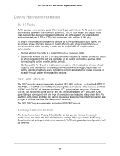
... GS716T, GS724T and GS748T all settings, including the password, VLAN settings and port configurations will be removed. 13 The SFP GBIC bay accommodates a standard SFP GBIC module. In this way, the Auto Uplink technology compensates for attaching devices, all RJ-45 ports support Auto Uplink.... The GBIC module bays accommodate standard SFP GBIC modules, such as when connecting the port to a router, switch, or hub). • Configures the RJ-45 port to a computer) or an "uplink" connection (such as the AGM731F, AGM732F, or AGM733 from NETGEAR, allowing fiber connections on the network...
... GS716T, GS724T and GS748T all settings, including the password, VLAN settings and port configurations will be removed. 13 The SFP GBIC bay accommodates a standard SFP GBIC module. In this way, the Auto Uplink technology compensates for attaching devices, all RJ-45 ports support Auto Uplink.... The GBIC module bays accommodate standard SFP GBIC modules, such as when connecting the port to a router, switch, or hub). • Configures the RJ-45 port to a computer) or an "uplink" connection (such as the AGM731F, AGM732F, or AGM733 from NETGEAR, allowing fiber connections on the network...
Hardware Installation Guide
Page 21
4. Installation 4 This chapter describes the installation procedures for your NETGEAR GS716T,GS724T and GS748T Series Smart Switch. Switch installation involves the following steps: Step 1: Prepare the Site Step 2: Install the Switch Step 3: Check the Installation Step 4: Connect Devices to the Switch Step 5: Install an SFP GBIC Module Step 6: Apply AC Power Step 7: Manage the Switch using a Web Browser or the Smart Control Center Utility 17
4. Installation 4 This chapter describes the installation procedures for your NETGEAR GS716T,GS724T and GS748T Series Smart Switch. Switch installation involves the following steps: Step 1: Prepare the Site Step 2: Install the Switch Step 3: Check the Installation Step 4: Connect Devices to the Switch Step 5: Install an SFP GBIC Module Step 6: Apply AC Power Step 7: Manage the Switch using a Web Browser or the Smart Control Center Utility 17
Hardware Installation Guide
Page 26
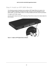
If an SFP GBIC module is not being installed at this time, skip this procedure. Install an SFP Gigabit Ethernet Module 22 To install an SFP GBIC module: Insert the SFP module into the connector. Standard SFP GBIC modules are sold separately from the Smart Switch. Press firmly to install an SFP Gigabit Ethernet module in the switch's Gigabit module bay. Tx Rx Figure 11. GS716T, GS724T and GS748T Gigabit Smart Switch Step 5: Install an SFP GBIC Module The following procedure describes how to ensure the module seats into the SFP module bay.
If an SFP GBIC module is not being installed at this time, skip this procedure. Install an SFP Gigabit Ethernet Module 22 To install an SFP GBIC module: Insert the SFP module into the connector. Standard SFP GBIC modules are sold separately from the Smart Switch. Press firmly to install an SFP Gigabit Ethernet module in the switch's Gigabit module bay. Tx Rx Figure 11. GS716T, GS724T and GS748T Gigabit Smart Switch Step 5: Install an SFP GBIC Module The following procedure describes how to ensure the module seats into the SFP module bay.
Hardware Installation Guide
Page 36
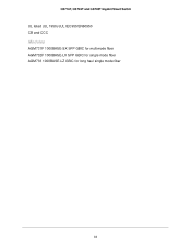
GS716T, GS724T and GS748T Gigabit Smart Switch UL listed (UL 1950)/cUL IEC950/EN60950 CB and CCC Modules AGM731F 1000BASE-SX SFP GBIC for multimode fiber AGM732F 1000BASE-LX SFP GBIC for single mode fiber AGM733 1000BASE-LZ GBIC for long haul single mode fiber 32
GS716T, GS724T and GS748T Gigabit Smart Switch UL listed (UL 1950)/cUL IEC950/EN60950 CB and CCC Modules AGM731F 1000BASE-SX SFP GBIC for multimode fiber AGM732F 1000BASE-LX SFP GBIC for single mode fiber AGM733 1000BASE-LZ GBIC for long haul single mode fiber 32
Hardware Installation Guide
Page 40
GS716T, GS724T and GS748T Gigabit Smart Switch F Factory Default Button 13 Factory Defaults 8, 10 Fiber Connectivity 4 Flat Surface 19 Full-duplex 4 G GBIC 4, 13 Gigabit Ports 4 H High-speed Servers 4 Hz 9, 11 I IEEE 802.3ab 5 IEEE 802.3i 5 IEEE 802.3u 5 IEEE 802.3x 5 IEEE 802.3z 5 IEEE Standards 5 IEEE-compliant 4 Installation Guide 6 Installing an SFP GBIC Module 22 Installing the Switch 19 L LED Designations 10, 11 LINK/ACT LED 11, 12 Low Latency 4 M MAC 5 Media Access Control 5 Mounting Holes 19 N Nylon Washers 19 O ON/OFF switch 23 Operating Conditions 18 Operating Environment 18 36
GS716T, GS724T and GS748T Gigabit Smart Switch F Factory Default Button 13 Factory Defaults 8, 10 Fiber Connectivity 4 Flat Surface 19 Full-duplex 4 G GBIC 4, 13 Gigabit Ports 4 H High-speed Servers 4 Hz 9, 11 I IEEE 802.3ab 5 IEEE 802.3i 5 IEEE 802.3u 5 IEEE 802.3x 5 IEEE 802.3z 5 IEEE Standards 5 IEEE-compliant 4 Installation Guide 6 Installing an SFP GBIC Module 22 Installing the Switch 19 L LED Designations 10, 11 LINK/ACT LED 11, 12 Low Latency 4 M MAC 5 Media Access Control 5 Mounting Holes 19 N Nylon Washers 19 O ON/OFF switch 23 Operating Conditions 18 Operating Environment 18 36
Hardware Installation Guide
Page 41
... the Site 18 R Rack 19 Rack-mount Kit 6, 19 Reset Button 8, 10 RJ-45 4 RJ-45 Ports 13 Rubber footpads 6, 19 S SFP GBIC Module 13 SFP LINK/ACT LED 11, 12 SFP Module Bay 22 Site Requirements 18 Smart Control Center 4 Smart Switch Resource CD 6 Straight-through 13 Support Information Card 6 System LEDs...
... the Site 18 R Rack 19 Rack-mount Kit 6, 19 Reset Button 8, 10 RJ-45 4 RJ-45 Ports 13 Rubber footpads 6, 19 S SFP GBIC Module 13 SFP LINK/ACT LED 11, 12 SFP Module Bay 22 Site Requirements 18 Smart Control Center 4 Smart Switch Resource CD 6 Straight-through 13 Support Information Card 6 System LEDs...
Software Administration Manual
Page 22
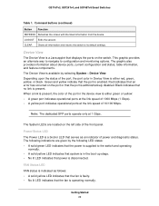
... A green port indicates operational ports at the link speed of 1000 Mbps (1 Gbps). • A yellow port indicates operational ports at 1 Gbps. GS716Tv3, GS724Tv4, and GS748Tv5 Smart Switches Table 1. Depending upon the status of the port, the port color in Device View is a bicolor LED that serves as follows...of the port in the boot-up stage. • No lit LED indicates that the port is administratively disabled. Note: The dedicated SFP ports operate only at the link speed of the front panel. This graphic provides an alternate way to navigate to its default settings. ...
... A green port indicates operational ports at the link speed of 1000 Mbps (1 Gbps). • A yellow port indicates operational ports at 1 Gbps. GS716Tv3, GS724Tv4, and GS748Tv5 Smart Switches Table 1. Depending upon the status of the port, the port color in Device View is a bicolor LED that serves as follows...of the port in the boot-up stage. • No lit LED indicates that the port is administratively disabled. Note: The dedicated SFP ports operate only at the link speed of the front panel. This graphic provides an alternate way to navigate to its default settings. ...
Software Administration Manual
Page 27
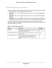
...combo ports that are only used as gigabit copper or SFP ports, and Ports 47-48 are as follows: • GS716Tv3. This interface is not configurable and is identified on the switch. GS716Tv3, GS724Tv4, and GS748Tv5 Smart Switches Interface Naming Convention The switch ... starting from one. Interface naming conventions Interface Description Example Physical The physical ports include gigabit ports and are dedicated gigabit SFP ports· • GS724Tv4. You can be used for the c1 switch base MAC address. Link aggregation group (LAG) LAG interfaces are logical...
...combo ports that are only used as gigabit copper or SFP ports, and Ports 47-48 are as follows: • GS716Tv3. This interface is not configurable and is identified on the switch. GS716Tv3, GS724Tv4, and GS748Tv5 Smart Switches Interface Naming Convention The switch ... starting from one. Interface naming conventions Interface Description Example Physical The physical ports include gigabit ports and are dedicated gigabit SFP ports· • GS724Tv4. You can be used for the c1 switch base MAC address. Link aggregation group (LAG) LAG interfaces are logical...
Software Administration Manual
Page 282
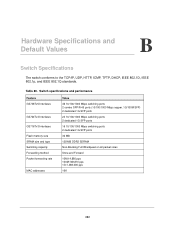
..., TFTP, DHCP, IEEE 802.1D, IEEE 802.1p, and IEEE 802.1Q standards. Table 80. B. Switch specifications and performance Feature GS748Tv5 Interfaces GS724Tv4 Interfaces GS716Tv3 Interfaces Flash memory size SRAM size and type Switching capacity Forwarding method Packet forwarding rate MAC addresses Value 46 10/100/1000 Mbps... switching ports 2 combo SFP/R-45 ports (10/100/1000 Mbps copper, 1G/100M SFP) 2 dedicated 1G SFP ports 24 10/100/1000 Mbps switching ports 2 dedicated 1G SFP ports 16 10/100/1000 Mbps switching ports 2 dedicated 1G SFP ports 32 MB 128 MB DDR2 SDRAM Non...
..., TFTP, DHCP, IEEE 802.1D, IEEE 802.1p, and IEEE 802.1Q standards. Table 80. B. Switch specifications and performance Feature GS748Tv5 Interfaces GS724Tv4 Interfaces GS716Tv3 Interfaces Flash memory size SRAM size and type Switching capacity Forwarding method Packet forwarding rate MAC addresses Value 46 10/100/1000 Mbps... switching ports 2 combo SFP/R-45 ports (10/100/1000 Mbps copper, 1G/100M SFP) 2 dedicated 1G SFP ports 24 10/100/1000 Mbps switching ports 2 dedicated 1G SFP ports 16 10/100/1000 Mbps switching ports 2 dedicated 1G SFP ports 32 MB 128 MB DDR2 SDRAM Non...