Shared access to the Internet for multiple VLANs - No routing
Page 1
...Setup ...3 Logical Setup ...3 DGFV338 Primary LAN ...4 DGFV338 Secondary VLAN ...5 Smartswitch VLAN creation ...6 Assigning Port membership to a VLAN 7 Assigning a PVID to obtain Internet access on top). The procedure described can apply to all the Smart Switches and VPN Firewall with new Web Interface (defined as the... one with the Menus appearing horizontally on multiple VLANs using MultiHoming This document describes how to a port...8 Testing the scenario ...10 Further notes......
...Setup ...3 Logical Setup ...3 DGFV338 Primary LAN ...4 DGFV338 Secondary VLAN ...5 Smartswitch VLAN creation ...6 Assigning Port membership to a VLAN 7 Assigning a PVID to obtain Internet access on top). The procedure described can apply to all the Smart Switches and VPN Firewall with new Web Interface (defined as the... one with the Menus appearing horizontally on multiple VLANs using MultiHoming This document describes how to a port...8 Testing the scenario ...10 Further notes......
Shared access to the Internet for multiple VLANs - No routing
Page 2
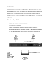
... 2 • A VLAN can be implemented. VLAN-Definition VLANs are attached. Notes when setting-up VLANs • A VLAN does not have a minimum number of time it takes for network changes, additions, and moves to be created per unit, device or via logical connection/combination • Broadcast and Multicast traffic is required 24 Port 10/100/1000 Mbps Smart Switch 1 3 5 7 9 11...
... 2 • A VLAN can be implemented. VLAN-Definition VLANs are attached. Notes when setting-up VLANs • A VLAN does not have a minimum number of time it takes for network changes, additions, and moves to be created per unit, device or via logical connection/combination • Broadcast and Multicast traffic is required 24 Port 10/100/1000 Mbps Smart Switch 1 3 5 7 9 11...
Shared access to the Internet for multiple VLANs - No routing
Page 3
...LAN port and give computers on VLAN1 (192.168.0.239) DGFV338 : Primary range 192.168.0.1/24 (DHCP enabled) Seconday range 172.16.0.1/24 (DHCP not enabled) PC1 - IMPORTANT! Firmware 3.1.0.1 2x Windows XP Computers (2 on each VLAN) 1 x DGFV338 Prosafe Firewall Router (Router firmware 3.4.0.19) Logical Setup GS724TS:... subnet 255.255.255.0 Physical Setup 1x GS724TS Prosafe Smartswitch - The hosts on the secondary subnets must be configured in the DHCP server. VLAN30 - 172.16.0.2/24 VLAN20: Ports 0/5 and 0/6 and 0/9 (PVID 20 for all the ports) VLAN30: Ports 0/7 and 0/8 and 0/9 (PVID 30 ...
...LAN port and give computers on VLAN1 (192.168.0.239) DGFV338 : Primary range 192.168.0.1/24 (DHCP enabled) Seconday range 172.16.0.1/24 (DHCP not enabled) PC1 - IMPORTANT! Firmware 3.1.0.1 2x Windows XP Computers (2 on each VLAN) 1 x DGFV338 Prosafe Firewall Router (Router firmware 3.4.0.19) Logical Setup GS724TS:... subnet 255.255.255.0 Physical Setup 1x GS724TS Prosafe Smartswitch - The hosts on the secondary subnets must be configured in the DHCP server. VLAN30 - 172.16.0.2/24 VLAN20: Ports 0/5 and 0/6 and 0/9 (PVID 20 for all the ports) VLAN30: Ports 0/7 and 0/8 and 0/9 (PVID 30 ...
Shared access to the Internet for multiple VLANs - No routing
Page 5
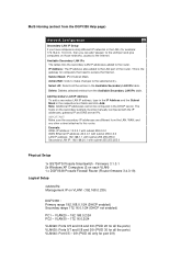
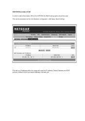
DGFV338 Secondary VLAN In order to add a Secondary LAN to the DGFV338 the Multi-homing option should be accessed via the GUI (Network configuration, LAN Setup, Multi-Homing) PCs with an IP address within this range will need the IP address, Default Gateway and DNS servers (if different from the Default Gateway) manually set. This can be used.
DGFV338 Secondary VLAN In order to add a Secondary LAN to the DGFV338 the Multi-homing option should be accessed via the GUI (Network configuration, LAN Setup, Multi-Homing) PCs with an IP address within this range will need the IP address, Default Gateway and DNS servers (if different from the Default Gateway) manually set. This can be used.
Shared access to the Internet for multiple VLANs - No routing
Page 6
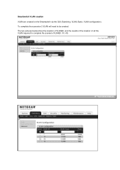
Smartswitch VLAN creation VLAN are created on the Smartswitch via the GUI (Switching, VLAN, Basic, VLAN configuration). To complete the scenarion 3 VLAN will need to complete the scenario (VLAN20, 30, 40) The two pictures below show the creation of VLAN20, and the results of the creation of all the VLAN required to be created.
Smartswitch VLAN creation VLAN are created on the Smartswitch via the GUI (Switching, VLAN, Basic, VLAN configuration). To complete the scenarion 3 VLAN will need to complete the scenario (VLAN20, 30, 40) The two pictures below show the creation of VLAN20, and the results of the creation of all the VLAN required to be created.
Shared access to the Internet for multiple VLANs - No routing
Page 7
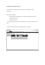
Tagged membership (T) In order to a VLAN Port membership can be using the U (Untagged) option on the gray box until the correct one is set. No membership (no simbol appearing in the gray box underneath the port number) - Untagged membership (U) - Three options are available: - Assigning Port membership to browse through the options just continuosly click on all the ports. For this scenarion we will be assigned via the GUI (Switching, VLAN, Advanced , VLAN membership).
Tagged membership (T) In order to a VLAN Port membership can be using the U (Untagged) option on the gray box until the correct one is set. No membership (no simbol appearing in the gray box underneath the port number) - Untagged membership (U) - Three options are available: - Assigning Port membership to browse through the options just continuosly click on all the ports. For this scenarion we will be assigned via the GUI (Switching, VLAN, Advanced , VLAN membership).
Shared access to the Internet for multiple VLANs - No routing
Page 8
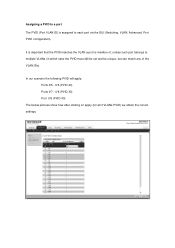
In our scenario the following PVID will apply: Ports 0/5 - 0/6 (PVID 20) Ports 0/7 - 0/8 (PVID 30) Port 0/9 (PVID 40) The below pictures show how after clicking on apply (for all 3 VLANs PVID) we obtain the correct settings: It is important that the PVID matches the VLAN a port is assigned to multiple VLANs (in which case the PVID must still be set and be unique, but can match any of the VLAN IDs). Assigning a PVID to a port The PVID (Port VLAN ID) is member of, unless such port belongs to each port via the GUI (Switching, VLAN, Advanced, Port PVID configuration).
In our scenario the following PVID will apply: Ports 0/5 - 0/6 (PVID 20) Ports 0/7 - 0/8 (PVID 30) Port 0/9 (PVID 40) The below pictures show how after clicking on apply (for all 3 VLANs PVID) we obtain the correct settings: It is important that the PVID matches the VLAN a port is assigned to multiple VLANs (in which case the PVID must still be set and be unique, but can match any of the VLAN IDs). Assigning a PVID to a port The PVID (Port VLAN ID) is member of, unless such port belongs to each port via the GUI (Switching, VLAN, Advanced, Port PVID configuration).
Shared access to the Internet for multiple VLANs - No routing
Page 10
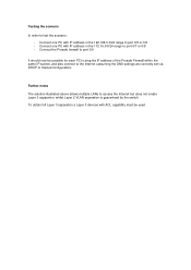
Connect one PC with ACL capability must be possible for each PC to ping the IP address of the Prosafe Firewall within the same IP subnet, and also connect to the Internet (assuming the DNS settings are correctly set via DHCP or manual configuration...separation a Layer 3 devices with IP address in the 192.168.0.0/24 range to port 0/7 or 0/8 - Testing the scenario In order to access the Internet but does not create Layer 3 separation, whilst Layer 2 VLAN separation is guaranteed by the switch. Connect the Prosafe firewall to port 0/9 It should now be used. Connect one PC with IP ...
Connect one PC with ACL capability must be possible for each PC to ping the IP address of the Prosafe Firewall within the same IP subnet, and also connect to the Internet (assuming the DNS settings are correctly set via DHCP or manual configuration...separation a Layer 3 devices with IP address in the 192.168.0.0/24 range to port 0/7 or 0/8 - Testing the scenario In order to access the Internet but does not create Layer 3 separation, whilst Layer 2 VLAN separation is guaranteed by the switch. Connect the Prosafe firewall to port 0/9 It should now be used. Connect one PC with IP ...
GS7xxTS Hardware manual
Page 11
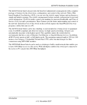
..., or Gigabit Ethernet devices. It is 328 feet (100 meters) over Category 5 Unshielded Twisted-Pair (UTP) cable, but much longer for environments that runs on a PC. In addition, all RJ-45 ports operate in a wiring closet or equipment room. The NETGEAR Smart Switch can be... the switch on the network requires the SmartWizard Discovery program, a utility that have 1000 Mbps access to have a mix of the network. Introduction v1.0, November 2007 1-14 The switch's management features include configuration for port and switch information, VLAN for traffic control, port trunking ...
..., or Gigabit Ethernet devices. It is 328 feet (100 meters) over Category 5 Unshielded Twisted-Pair (UTP) cable, but much longer for environments that runs on a PC. In addition, all RJ-45 ports operate in a wiring closet or equipment room. The NETGEAR Smart Switch can be... the switch on the network requires the SmartWizard Discovery program, a utility that have 1000 Mbps access to have a mix of the network. Introduction v1.0, November 2007 1-14 The switch's management features include configuration for port and switch information, VLAN for traffic control, port trunking ...
GS7xxTS Hardware manual
Page 22
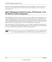
... The NETGEAR Smart Switch contains software for the first time, you to work. This management software is not required for the switch to setup VLAN and Trunking features, and also improves the efficiency of the switch, which...ports without using a Web browser or a utility program called SmartWizard Discovery. The default IP address is functioning correctly. For more information about managing the switch, see the Software Manual on the device. GS700TS Hardware Installation Guide If the Power LED does light up , there is a default IP address already configured on the Smart Switch...
... The NETGEAR Smart Switch contains software for the first time, you to work. This management software is not required for the switch to setup VLAN and Trunking features, and also improves the efficiency of the switch, which...ports without using a Web browser or a utility program called SmartWizard Discovery. The default IP address is functioning correctly. For more information about managing the switch, see the Software Manual on the device. GS700TS Hardware Installation Guide If the Power LED does light up , there is a default IP address already configured on the Smart Switch...

GS7xxTS Hardware manual
Page 28
... If both copper and fiber port cannot be active at the same time, the fiber port becomes active. SFP GBIC Module The GBIC module bays accommodate standard SFP GBIC modules, such as the AGM731F, AGM732F, or AGM733 from NETGEAR, allowing fiber connections on the..., including the password, VLAN settings and port configurations. 3-24 v1.0, November 2007 Physical Description In this way, the Auto Uplink technology compensates for setting uplink connections, while eliminating concern about whether to the factory settings. Factory Defaults Button The Smart Switch has a Factory default button...
... If both copper and fiber port cannot be active at the same time, the fiber port becomes active. SFP GBIC Module The GBIC module bays accommodate standard SFP GBIC modules, such as the AGM731F, AGM732F, or AGM733 from NETGEAR, allowing fiber connections on the..., including the password, VLAN settings and port configurations. 3-24 v1.0, November 2007 Physical Description In this way, the Auto Uplink technology compensates for setting uplink connections, while eliminating concern about whether to the factory settings. Factory Defaults Button The Smart Switch has a Factory default button...
GS7xxTS Hardware manual
Page 32
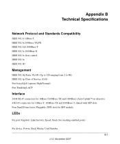
...port (Gigabit): Link/Activity, Speed, Stack (for SFP module. Appendix B Technical Specifications Network Protocol and Standards Compatibility IEEE 802.3i 10Base-T IEEE 802.3u 100Base-TX,FX IEEE 802.3ab 1000Base-T IEEE 802.3z 1000Base-X IEEE 802.3x flow control IEEE 802.1x IEEE 802.1D Management IEEE 802.1Q Static VLAN... (Up to 128 ranging from 2 to 4K) IEEE 802.1p Class of Service (CoS) Port-based QoS (options High/Normal) Port Trunking LACP Interface 24/48 RJ-45 connectors for 10Base-T,100Base-TX and 1000Base-(Auto Uplink™...
...port (Gigabit): Link/Activity, Speed, Stack (for SFP module. Appendix B Technical Specifications Network Protocol and Standards Compatibility IEEE 802.3i 10Base-T IEEE 802.3u 100Base-TX,FX IEEE 802.3ab 1000Base-T IEEE 802.3z 1000Base-X IEEE 802.3x flow control IEEE 802.1x IEEE 802.1D Management IEEE 802.1Q Static VLAN... (Up to 128 ranging from 2 to 4K) IEEE 802.1p Class of Service (CoS) Port-based QoS (options High/Normal) Port Trunking LACP Interface 24/48 RJ-45 connectors for 10Base-T,100Base-TX and 1000Base-(Auto Uplink™...
GS7xxTS Hardware manual
Page 37
User's Manual 1-4 UTP 4-16 V Ventilation 4-14 VLAN 1-1 W Warranty 1-4 Web-based Graphical User Interface 1-1 v1.0, November 2007 Index-3
User's Manual 1-4 UTP 4-16 V Ventilation 4-14 VLAN 1-1 W Warranty 1-4 Web-based Graphical User Interface 1-1 v1.0, November 2007 Index-3
GS7xxTS User Manual
Page 6
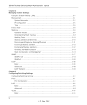
GS700TS Smart Switch Software Administration Manual Chapter 3 Managing System Settings Using the System Settings Utility 3-1 Management ...3-1 System Information 3-1 IP Configuration ...3-4 Time ...3-5 Device View ...3-8 Stacking ...3-8 Operation Modes ...3-9 Understanding Stack Topology 3-9 Stacking Ports ...3-10 Stacking Members and Unit No 3-10 Removing and Replacing Stacking Members 3-11 Inserting a Stacking Member 3-12 Exchanging Stacking Members 3-12 Switching the Stacking...
GS700TS Smart Switch Software Administration Manual Chapter 3 Managing System Settings Using the System Settings Utility 3-1 Management ...3-1 System Information 3-1 IP Configuration ...3-4 Time ...3-5 Device View ...3-8 Stacking ...3-8 Operation Modes ...3-9 Understanding Stack Topology 3-9 Stacking Ports ...3-10 Stacking Members and Unit No 3-10 Removing and Replacing Stacking Members 3-11 Inserting a Stacking Member 3-12 Exchanging Stacking Members 3-12 Switching the Stacking...
GS7xxTS User Manual
Page 7
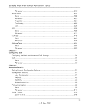
GS700TS Smart Switch Software Administration Manual Advanced ...4-16 Voice VLAN ...4-21 Basic ...4-22 Advanced ...4-23 Properties ...4-24 Port Setting ...4-25 OUI ...4-26 STP ...4-28 Basic ...4-28 Advanced ...4-31 Multicast ...4-43 Basic ...4-43 Advanced ...4-45 Address ... ...5-2 Advanced ...5-7 Chapter 6 Managing Security Setting Security Configuration Options 6-1 Management Security ...6-1 User Configuration 6-1 RADIUS ...6-2 TACACS+ ...6-6 Authentication List ...6-8 Port Authentication ...6-9 Basic ...6-9 Advanced ...6-11 Traffic Control ...6-15 Storm Control ...6-15 vii v1.0, June 2009
GS700TS Smart Switch Software Administration Manual Advanced ...4-16 Voice VLAN ...4-21 Basic ...4-22 Advanced ...4-23 Properties ...4-24 Port Setting ...4-25 OUI ...4-26 STP ...4-28 Basic ...4-28 Advanced ...4-31 Multicast ...4-43 Basic ...4-43 Advanced ...4-45 Address ... ...5-2 Advanced ...5-7 Chapter 6 Managing Security Setting Security Configuration Options 6-1 Management Security ...6-1 User Configuration 6-1 RADIUS ...6-2 TACACS+ ...6-6 Authentication List ...6-8 Port Authentication ...6-9 Basic ...6-9 Advanced ...6-11 Traffic Control ...6-15 Storm Control ...6-15 vii v1.0, June 2009
GS7xxTS User Manual
Page 15
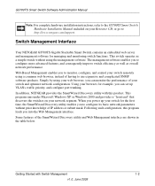
... XP or Windows 2000 and provides a "front end" that discovers the switches on your switch for the first time, the SmartWizard Discovery utility enables you to http://www.netgear.com/support. Some features of your network segment. Switch Management Interface Your NETGEAR GS700TS Gigabit Stackable Smart Switch contains an embedded web server and management software for managing and monitoring...
... XP or Windows 2000 and provides a "front end" that discovers the switches on your switch for the first time, the SmartWizard Discovery utility enables you to http://www.netgear.com/support. Some features of your network segment. Switch Management Interface Your NETGEAR GS700TS Gigabit Stackable Smart Switch contains an embedded web server and management software for managing and monitoring...

GS7xxTS User Manual
Page 27
... to access and use these functions, see Chapter 9, "Online Help". Displays untagged port members of a VLAN. Introduction to informational services including NETGEAR online support and an online user guide in PDF format. Resets statistics counters. Selects the specified interface. GS700TS Smart Switch Software Administration Manual Table 2-1. To access the help and device information and are...
... to access and use these functions, see Chapter 9, "Online Help". Displays untagged port members of a VLAN. Introduction to informational services including NETGEAR online support and an online user guide in PDF format. Resets statistics counters. Selects the specified interface. GS700TS Smart Switch Software Administration Manual Table 2-1. To access the help and device information and are...
GS7xxTS User Manual
Page 31
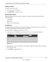
...port level. Select the Unit 1 ports to be deleted. 2. GS700TS Smart Switch Software Administration Manual Deleting an Entry To delete entries from a table: 1. The following options: • Gold Buttons • Quick Boxes • Interface View and Selection Gold Buttons Gold Buttons provide flexibility in viewing and configuring VLANs/LAGs on the Unit 1 ports... the device. Special Table Options The NETGEAR web browser interface tables have a unique GUI design which includes the following example displays gold button basic usage options. The Unit 1 ports panel is displayed: Figure 2-10 ...
...port level. Select the Unit 1 ports to be deleted. 2. GS700TS Smart Switch Software Administration Manual Deleting an Entry To delete entries from a table: 1. The following options: • Gold Buttons • Quick Boxes • Interface View and Selection Gold Buttons Gold Buttons provide flexibility in viewing and configuring VLANs/LAGs on the Unit 1 ports... the device. Special Table Options The NETGEAR web browser interface tables have a unique GUI design which includes the following example displays gold button basic usage options. The Unit 1 ports panel is displayed: Figure 2-10 ...

GS7xxTS User Manual
Page 32
... or unmark all Tagged. Figure 2-11 2. The following example displays quick box basic usage options. A T appears in the quick box. GS700TS Smart Switch Software Administration Manual Quick Boxes Quick Boxes provide users with flexibility in configuring VLANs for Unit 1, marking the ports as Tagged. Clicking on the Unit 1 gold button to display the Unit...
... or unmark all Tagged. Figure 2-11 2. The following example displays quick box basic usage options. A T appears in the quick box. GS700TS Smart Switch Software Administration Manual Quick Boxes Quick Boxes provide users with flexibility in configuring VLANs for Unit 1, marking the ports as Tagged. Clicking on the Unit 1 gold button to display the Unit...
GS7xxTS User Manual
Page 39
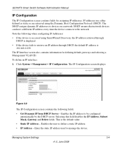
... device. Enter the static IP address used to define a static IP address. • IP Address - GS700TS Smart Switch Software Administration Manual IP Configuration The IP Configuration screen contains fields for defining default gateways and selecting a Management VLAN ID. DHCP ensures that network devices can have a different IP address every time the device connects...
... device. Enter the static IP address used to define a static IP address. • IP Address - GS700TS Smart Switch Software Administration Manual IP Configuration The IP Configuration screen contains fields for defining default gateways and selecting a Management VLAN ID. DHCP ensures that network devices can have a different IP address every time the device connects...


