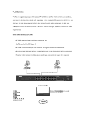
Shared access to the Internet for multiple VLANs - No routing
Page 2
...have a minimum number of the physical LAN segment to r y Defaults ProSafe VPN Wireless ADSL Gateway MODEL DGFV 338 PWR TEST IN TERN ET ...network devices into a single unit, regardless of port • VLANs work at protocol level (Layer 3) is required 24 Port 10/100/1000 Mbps Smart Switch 1 3 5 7 9 11 13 15... 17 19 21 23 LINK/ACT SPD Green = 100Mbps Yellow = 10Mbps FD X 2 4 6 8 10 12 14 16 18 20 22 24 LINK/ACT SPD FD X Reset PWR 1 3 5 7 9 11 2 4 6 8 10 12 13 15 17 19 21 23T 14 16 18 20 22 24T 23F 24F SFP LINK SFP LINK MODEL GS724T...
...have a minimum number of the physical LAN segment to r y Defaults ProSafe VPN Wireless ADSL Gateway MODEL DGFV 338 PWR TEST IN TERN ET ...network devices into a single unit, regardless of port • VLANs work at protocol level (Layer 3) is required 24 Port 10/100/1000 Mbps Smart Switch 1 3 5 7 9 11 13 15... 17 19 21 23 LINK/ACT SPD Green = 100Mbps Yellow = 10Mbps FD X 2 4 6 8 10 12 14 16 18 20 22 24 LINK/ACT SPD FD X Reset PWR 1 3 5 7 9 11 2 4 6 8 10 12 13 15 17 19 21 23T 14 16 18 20 22 24T 23F 24F SFP LINK SFP LINK MODEL GS724T...
GS7xxTS Hardware manual
Page 5
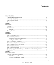
...2 Installation Step 1: Preparing the Site 2-29 Step 2: Installing the Switch 2-30 Installing the Switch on a Flat Surface 2-30 Installing the Switch in a Rack 2-30 Step 3: Checking the Installation 2-31 Step 4: Connecting Devices to the Switch 2-32 Step 5: Installing an SFP GBIC Module 2-32 Step 6: ...Device 2-33 Step 7: Applying AC Power 2-34 Step 8: Managing the Switch through a Web Browser or the PC Utility for Initial Configuration ...2-35 Chapter 3 Physical Description Front and Back Panel Configuration 3-19 GS724TS Front and Back Panels 3-19 GS748TS Front and Back Panels 3-20 ...
...2 Installation Step 1: Preparing the Site 2-29 Step 2: Installing the Switch 2-30 Installing the Switch on a Flat Surface 2-30 Installing the Switch in a Rack 2-30 Step 3: Checking the Installation 2-31 Step 4: Connecting Devices to the Switch 2-32 Step 5: Installing an SFP GBIC Module 2-32 Step 6: ...Device 2-33 Step 7: Applying AC Power 2-34 Step 8: Managing the Switch through a Web Browser or the PC Utility for Initial Configuration ...2-35 Chapter 3 Physical Description Front and Back Panel Configuration 3-19 GS724TS Front and Back Panels 3-19 GS748TS Front and Back Panels 3-20 ...
GS7xxTS Hardware manual
Page 10
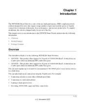
...24 ports of 10/100/1000 BaseT of which four are Combo ports with four additional SFP combo fiber ports. • GS748TS - For example: • Connecting switches to each other with four additional SFP combo fiber ports. You can use out of the box. Chapter 1 Introduction The NETGEAR Smart Switch... require a large number of ports and want the power of Gigabit connectivity to eliminate bottlenecks, boost performance, and increase productivity. You can stack together up to the GS700TS Smart Switch and provides the following NETGEAR Smart Switches: • GS724TS - This chapter serves as ...
...24 ports of 10/100/1000 BaseT of which four are Combo ports with four additional SFP combo fiber ports. • GS748TS - For example: • Connecting switches to each other with four additional SFP combo fiber ports. You can use out of the box. Chapter 1 Introduction The NETGEAR Smart Switch... require a large number of ports and want the power of Gigabit connectivity to eliminate bottlenecks, boost performance, and increase productivity. You can stack together up to the GS700TS Smart Switch and provides the following NETGEAR Smart Switches: • GS724TS - This chapter serves as ...

GS7xxTS Hardware manual
Page 23
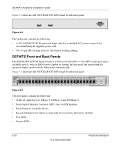
Figure 3-1 illustrates the NETGEAR GS724TS Smart Switch front panel: Figure 3-1 The front panel contains the following: • 24 RJ-45 connectors for 10Base-T, 100Base-T and 1000Base-T. • Four SFP slots for SFP modules supporting 1000(1000Base...Back Panels • LED Designations • Device Hardware Interfaces Front and Back Panel Configuration GS724TS Front and Back Panels The NETGEAR GS724TS Smart Switch is a 24-Port 10/100/1000 + 4-Port SFP Combo port switch, with each RJ45 ports capable of sensing the line speed and negotiating the operation duplex mode with the link ...
Figure 3-1 illustrates the NETGEAR GS724TS Smart Switch front panel: Figure 3-1 The front panel contains the following: • 24 RJ-45 connectors for 10Base-T, 100Base-T and 1000Base-T. • Four SFP slots for SFP modules supporting 1000(1000Base...Back Panels • LED Designations • Device Hardware Interfaces Front and Back Panel Configuration GS724TS Front and Back Panels The NETGEAR GS724TS Smart Switch is a 24-Port 10/100/1000 + 4-Port SFP Combo port switch, with each RJ45 ports capable of sensing the line speed and negotiating the operation duplex mode with the link ...
GS7xxTS Hardware manual
Page 24
...NETGEAR GS724TS Smart Switch back panel: Figure 3-2 The back panel contains the following : • 48 RJ-45 connectors for 10Base-T, 100Base-T and 1000Base-T. • Four Gigabit Interface Converter (SFP) slots for full-duplex stacking linking. GS748TS Front and Back Panels The NETGEAR GS748TS Smart Switch... 3-3 illustrates the NETGEAR GS748TS Smart Switch front panel: Figure 3-3 The front panel contains the following : • A 100-240VAC/50-60 Hz universal input, which is a 48-Port 10/100/1000 + 4-Port SFP Combo port smart stackable switch, with each RJ45 ports capable of sensing the...
...NETGEAR GS724TS Smart Switch back panel: Figure 3-2 The back panel contains the following : • 48 RJ-45 connectors for 10Base-T, 100Base-T and 1000Base-T. • Four Gigabit Interface Converter (SFP) slots for full-duplex stacking linking. GS748TS Front and Back Panels The NETGEAR GS748TS Smart Switch... 3-3 illustrates the NETGEAR GS748TS Smart Switch front panel: Figure 3-3 The front panel contains the following : • A 100-240VAC/50-60 Hz universal input, which is a 48-Port 10/100/1000 + 4-Port SFP Combo port smart stackable switch, with each RJ45 ports capable of sensing the...


