
GS7xxTPS Hardware manual
Page 5
... ...1-7 Chapter 2 Installation Step 1: Preparing the Site 2-1 Step 2: Installing the Switch 2-2 Step 3: Checking the Installation 2-3 Step 4: Connecting Devices to the Switch 2-4 Step 5: Installing an SFP GBIC Module 2-5 Step 6 Installing Device as Stand-alone or Stack Master 2-5 Step 7: Applying AC Power 2-7 Step 8: Managing the Switch via a Web Browser/PC Utility for Initial Configuration ......2-7 Chapter 3 ...
... ...1-7 Chapter 2 Installation Step 1: Preparing the Site 2-1 Step 2: Installing the Switch 2-2 Step 3: Checking the Installation 2-3 Step 4: Connecting Devices to the Switch 2-4 Step 5: Installing an SFP GBIC Module 2-5 Step 6 Installing Device as Stand-alone or Stack Master 2-5 Step 7: Applying AC Power 2-7 Step 8: Managing the Switch via a Web Browser/PC Utility for Initial Configuration ......2-7 Chapter 3 ...

GS7xxTPS Hardware manual
Page 14
...-T) • IEEE 802.3z (1000Base-X) • IEEE 802.3at (DTE Power via the device's HX Stack ports. • The following SFP types are the four 10/100/1000M auto-sensing Giga switching ports on all 10/100/1000 Mbps ports. • Store-and-Forward transmission to remove bad packets from... copper ports corresponding to the Combo ports are supported: • 1000Base-SX • 1000Base-LX • 100Base-FX • The device supports full Netgear Smart Switch functionality. • The device provides full compatibility with two physical connections, SFP fiber and RJ-45 copper.
...-T) • IEEE 802.3z (1000Base-X) • IEEE 802.3at (DTE Power via the device's HX Stack ports. • The following SFP types are the four 10/100/1000M auto-sensing Giga switching ports on all 10/100/1000 Mbps ports. • Store-and-Forward transmission to remove bad packets from... copper ports corresponding to the Combo ports are supported: • 1000Base-SX • 1000Base-LX • 100Base-FX • The device supports full Netgear Smart Switch functionality. • The device provides full compatibility with two physical connections, SFP fiber and RJ-45 copper.

GS7xxTPS Hardware manual
Page 15
... stack. GS748TPS supports the following PoE functions: • Smart Power Managed function handles the power of each port in the event of limited available power. • Supports the 48-Port PoE functions as the backup master. GS700TPS Smart Switch • Standard 1U high, rack mountable 19"chassis. • Fan speed control supported The GS724TPS supports the following PoE...
... stack. GS748TPS supports the following PoE functions: • Smart Power Managed function handles the power of each port in the event of limited available power. • Supports the 48-Port PoE functions as the backup master. GS700TPS Smart Switch • Standard 1U high, rack mountable 19"chassis. • Fan speed control supported The GS724TPS supports the following PoE...

GS7xxTPS Hardware manual
Page 16
...Modes: • Standalone unit runs as a general switch. If the master unit fails, the masterbackup unit will assume the stack-master role. ("Switchover"). • A slave unit only runs a slave version of the Distributed Switching Algorithm, which to update and synchronize the Backup master.... • A master-backup unit runs as a slave unit as a single interface in the event of failure of 1 and 2. GS700TPS Smart Switch stack master in which allows the applications running ...
...Modes: • Standalone unit runs as a general switch. If the master unit fails, the masterbackup unit will assume the stack-master role. ("Switchover"). • A slave unit only runs a slave version of the Distributed Switching Algorithm, which to update and synchronize the Backup master.... • A master-backup unit runs as a slave unit as a single interface in the event of failure of 1 and 2. GS700TPS Smart Switch stack master in which allows the applications running ...

GS7xxTPS Hardware manual
Page 17
... 2009 Figure 1-2 Verify that the package contains the following: • NETGEAR Smart Switch • Stacking Cable • Rubber footpads for tabletop installation • Power cord • Rack-mount Kit for installing the switch in a 19-inch rack • Installation Guide • Smart Switch Resource CD with Smart Wizard Discovery and User's manual • Warranty/Support Information Card If...
... 2009 Figure 1-2 Verify that the package contains the following: • NETGEAR Smart Switch • Stacking Cable • Rubber footpads for tabletop installation • Power cord • Rack-mount Kit for installing the switch in a 19-inch rack • Installation Guide • Smart Switch Resource CD with Smart Wizard Discovery and User's manual • Warranty/Support Information Card If...

GS7xxTPS Hardware manual
Page 19
... 5: Installing an SFP GBIC Module" "Step 6 Installing Device as Stand-alone or Stack Master" "Step 7: Applying AC Power" "Step 8: Managing the Switch via a Web Browser/PC Utility for your NETGEAR Smart Switch. The rack-mount kit supplied with the switch is grounded and physically secure. Chapter 2 Installation This chapter describes the installation procedures for Initial Configuration...
... 5: Installing an SFP GBIC Module" "Step 6 Installing Device as Stand-alone or Stack Master" "Step 7: Applying AC Power" "Step 8: Managing the Switch via a Web Browser/PC Utility for your NETGEAR Smart Switch. The rack-mount kit supplied with the switch is grounded and physically secure. Chapter 2 Installation This chapter describes the installation procedures for Initial Configuration...

GS7xxTPS Hardware manual
Page 23
... the switch's Gigabit module bay. If the master unit fails, the master-backup unit will set all their ports to ensure the module seats into the SFP module bay. 2. Standard SFP GBIC modules are sold separately from the stack (which puts them in a chain topology, slave units could be disjointed from the Smart Switch. GS700TPS Smart Switch...
... the switch's Gigabit module bay. If the master unit fails, the master-backup unit will set all their ports to ensure the module seats into the SFP module bay. 2. Standard SFP GBIC modules are sold separately from the stack (which puts them in a chain topology, slave units could be disjointed from the Smart Switch. GS700TPS Smart Switch...

GS7xxTPS Hardware manual
Page 24
... software, and can be changed by a unit reset. GS700TPS Smart Switch Each unit may work in stand-alone mode. Setting the unit mode can only be done either by the device, the Ring topology or Chain topology. Before powering up the devices. The stacking 7 Segment LED is not illuminated (off) if the unit...
... software, and can be changed by a unit reset. GS700TPS Smart Switch Each unit may work in stand-alone mode. Setting the unit mode can only be done either by the device, the Ring topology or Chain topology. Before powering up the devices. The stacking 7 Segment LED is not illuminated (off) if the unit...

GS7xxTPS Hardware manual
Page 29
LED Designations This section provides an explanation for the following : • A 100-240VAC/50-60 Hz universal input RS-232 Console interface, which is a standard AC power receptacle for accommodating the supplied power cord. • Two 19 pin Gbps HX stacking ports. GS700TPS Smart Switch The back panel contains the following LED types: • "Port LEDs" • "System LEDS" Physical Description 3-3 v1.0, April 2009
LED Designations This section provides an explanation for the following : • A 100-240VAC/50-60 Hz universal input RS-232 Console interface, which is a standard AC power receptacle for accommodating the supplied power cord. • Two 19 pin Gbps HX stacking ports. GS700TPS Smart Switch The back panel contains the following LED types: • "Port LEDs" • "System LEDS" Physical Description 3-3 v1.0, April 2009

GS7xxTPS Hardware manual
Page 31
...Smart Switch Table 3-2. One Seven Segment LED Display Stack Master LED Stack Port LED Designation • Off - Power is operating normally. • Solid Yellow - FAN is disconnected. • Solid Green - LED Mode in the • previous two minutes. • Solid Green - Power is supplied to the switch... section provides information for another device. • Solid Yellow - Indicates the PoE MAX LED was active in PoE LED Mode. • Green - Switch acts as a master unit in a stack of PoE power available for the following hardware interfaces: • "RJ-45 Ports" ...
...Smart Switch Table 3-2. One Seven Segment LED Display Stack Master LED Stack Port LED Designation • Off - Power is operating normally. • Solid Yellow - FAN is disconnected. • Solid Green - LED Mode in the • previous two minutes. • Solid Green - Power is supplied to the switch... section provides information for another device. • Solid Yellow - Indicates the PoE MAX LED was active in PoE LED Mode. • Green - Switch acts as a master unit in a stack of PoE power available for the following hardware interfaces: • "RJ-45 Ports" ...

GS7xxTPS Hardware manual
Page 32
... an "uplink" connection (such as the AGM731F, AGM732F, or AGM733 from NETGEAR, allowing fiber connections on the network. The module bay is a straight-through or crossover cables. When inserting a cable into the switch's RJ-45 port, the switch automatically: • Senses whether the cable is a combo port, sharing a...mode (half-or fullduplex) of 20 Gbps (aggregate, bi-directional) via the device's HX Stack ports. The following types of connection can be used at any given time. GS700TPS Smart Switch RJ-45 Ports RJ-45 ports are plugged in at the same time, the fiber port ...
... an "uplink" connection (such as the AGM731F, AGM732F, or AGM733 from NETGEAR, allowing fiber connections on the network. The module bay is a straight-through or crossover cables. When inserting a cable into the switch's RJ-45 port, the switch automatically: • Senses whether the cable is a combo port, sharing a...mode (half-or fullduplex) of 20 Gbps (aggregate, bi-directional) via the device's HX Stack ports. The following types of connection can be used at any given time. GS700TPS Smart Switch RJ-45 Ports RJ-45 ports are plugged in at the same time, the fiber port ...
GS7xxTPS Hardware manual
Page 33
Physical Description 3-7 v1.0, April 2009 GS700TPS Smart Switch Factory Defaults Button The Smart Switch has a Factory default button to enable clearing the current configuration and returning the device back to the factory settings. If the switches are in a stack, the stacking settings are cleared by the Factory Defaults Button. This removes all settings, including the password, VLAN settings and port configurations.
Physical Description 3-7 v1.0, April 2009 GS700TPS Smart Switch Factory Defaults Button The Smart Switch has a Factory default button to enable clearing the current configuration and returning the device back to the factory settings. If the switches are in a stack, the stacking settings are cleared by the Factory Defaults Button. This removes all settings, including the password, VLAN settings and port configurations.

GS7xxTPS Hardware manual
Page 36
... Default" button. Ensure that there is configured as the stacking ports. To reset the switch, disconnect the AC power from the stack. In North America, call 1-888-NETGEAR. GS700TPS Smart Switch Table A-1. The stacking ports of the installation do not resolve the problem, refer to configure the unit as a stackable unit, with your product. Additional Troubleshooting Suggestions If...
... Default" button. Ensure that there is configured as the stacking ports. To reset the switch, disconnect the AC power from the stack. In North America, call 1-888-NETGEAR. GS700TPS Smart Switch Table A-1. The stacking ports of the installation do not resolve the problem, refer to configure the unit as a stackable unit, with your product. Additional Troubleshooting Suggestions If...

GS7xxTPS Hardware manual
Page 39
Microsoft Explorer 6.0 IEEE 802.1p Class of Service (CoS) SNMPv3 Interface 24/48-RJ-45 connectors for stacking-enabled ports) Per device: Power, FAN, Stack ID, Stack Master, Max PoE Performance Specifications Forwarding modes: Store-and-forward Address database size: 8K media access control (MAC) addresses per system B-1 v1.0, April 2009 Appendix B ... 2000 + XP; Four Small Form-factor Pluggable (SFP) slots, supported 1000(1000Base-SX/LX)/100M SFP LEDs Per port LEDs: Link Status or PoE Status, Stack Link Status (for 10Base-T,100Base-TX and 1000Base-(Auto Uplink™ on all ports).
Microsoft Explorer 6.0 IEEE 802.1p Class of Service (CoS) SNMPv3 Interface 24/48-RJ-45 connectors for stacking-enabled ports) Per device: Power, FAN, Stack ID, Stack Master, Max PoE Performance Specifications Forwarding modes: Store-and-forward Address database size: 8K media access control (MAC) addresses per system B-1 v1.0, April 2009 Appendix B ... 2000 + XP; Four Small Form-factor Pluggable (SFP) slots, supported 1000(1000Base-SX/LX)/100M SFP LEDs Per port LEDs: Link Status or PoE Status, Stack Link Status (for 10Base-T,100Base-TX and 1000Base-(Auto Uplink™ on all ports).

GS7xxTPS User Manual
Page 6
... Smart Switch Software Administration Manual Chapter 3 Managing System Settings Using the System Settings Utility 3-1 Management ...3-1 System Information 3-1 IP Configuration ...3-4 Time ...3-5 Device View ...3-8 Stacking ...3-8 Operation Modes ...3-9 Understanding Stack Topology 3-10 Stacking Ports ...3-10 Stacking Members and Unit No 3-10 Removing and Replacing Stacking Members 3-11 Inserting a Stacking Member 3-12 Exchanging Stacking Members 3-12 Switching the Stacking Master 3-13 Stack Configuration and Management 3-13 PoE...
... Smart Switch Software Administration Manual Chapter 3 Managing System Settings Using the System Settings Utility 3-1 Management ...3-1 System Information 3-1 IP Configuration ...3-4 Time ...3-5 Device View ...3-8 Stacking ...3-8 Operation Modes ...3-9 Understanding Stack Topology 3-10 Stacking Ports ...3-10 Stacking Members and Unit No 3-10 Removing and Replacing Stacking Members 3-11 Inserting a Stacking Member 3-12 Exchanging Stacking Members 3-12 Switching the Stacking Master 3-13 Stack Configuration and Management 3-13 PoE...
GS7xxTPS User Manual
Page 23
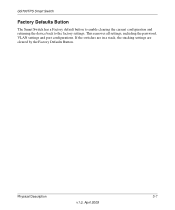
...switch to the Upgrade Configuration. 3. Click Apply to apply the settings to upgrade, the following values into the appropriate places in progress.When the process is password. 2. GS700TPS Smart Switch Software Administration Manual If you click Firmware Upgrade from the SmartWizard Discovery screen to all stacking... members. the default password is complete, the switch automatically reboots.
...switch to the Upgrade Configuration. 3. Click Apply to apply the settings to upgrade, the following values into the appropriate places in progress.When the process is password. 2. GS700TPS Smart Switch Software Administration Manual If you click Firmware Upgrade from the SmartWizard Discovery screen to all stacking... members. the default password is complete, the switch automatically reboots.
GS7xxTPS User Manual
Page 32
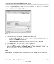
... all Tagged. Click again on the Unit 1 gold button to the left -hand side of the Unit 1 gold button. Clicking on a stacking unit level) or LAGs. Figure 2-10 3. GS700TPS Smart Switch Software Administration Manual Quick Boxes Quick Boxes provide users with flexibility in configuring VLANs for all Unit 1ports: 1. To mark or unmark...
... all Tagged. Click again on the Unit 1 gold button to the left -hand side of the Unit 1 gold button. Clicking on a stacking unit level) or LAGs. Figure 2-10 3. GS700TPS Smart Switch Software Administration Manual Quick Boxes Quick Boxes provide users with flexibility in configuring VLANs for all Unit 1ports: 1. To mark or unmark...

GS7xxTPS User Manual
Page 33
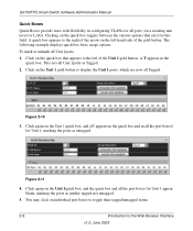
... row. Figure 2-13 2. A confirmation window opens. The screen displays a table of column headers. Clicking on the Unit No. To display all interfaces in all stacking units. GS700TPS Smart Switch Software Administration Manual Interface View and Selection A port or LAG interface may be selected from a table by using the interface selection row, located above...
... row. Figure 2-13 2. A confirmation window opens. The screen displays a table of column headers. Clicking on the Unit No. To display all interfaces in all stacking units. GS700TPS Smart Switch Software Administration Manual Interface View and Selection A port or LAG interface may be selected from a table by using the interface selection row, located above...

GS7xxTPS User Manual
Page 35
... screen displays basic device information and allows network managers to manage your GS700TPS Smart Switch displaying configurable features under the following main menu options: • "Management" • "Device View" • "Stacking" • "PoE" • "SNMP" • "LLDP" The description that enables you...browser interface contains a System tab that follows in this chapter describes configuring and managing system settings in the GS700TPS Smart Switch. Chapter 3 Managing System Settings Using the System Settings Utility The navigation pane at the top of general device information...
... screen displays basic device information and allows network managers to manage your GS700TPS Smart Switch displaying configurable features under the following main menu options: • "Management" • "Device View" • "Stacking" • "PoE" • "SNMP" • "LLDP" The description that enables you...browser interface contains a System tab that follows in this chapter describes configuring and managing system settings in the GS700TPS Smart Switch. Chapter 3 Managing System Settings Using the System Settings Utility The navigation pane at the top of general device information...

GS7xxTPS User Manual
Page 37
...Displays the stacking member's current number. If the displayed Unit Mode needs to update the system settings. 6. Idle stations that elapses before an idle station is timed out. Displays the Jumbo Frame status. • Jumbo Frames After Reset - Disables Jumbo Frames. GS700TPS Smart Switch Software ... Enables Jumbo Frames. - Managing System Settings 3-3 v1.0, June 2009 Displays the MAC Address. Select whether to the value indicated by Stack or Standalone after resetting the device. • Jumbo Frames Status - See "Reset" for the new unit mode setting to the system...
...Displays the stacking member's current number. If the displayed Unit Mode needs to update the system settings. 6. Idle stations that elapses before an idle station is timed out. Displays the Jumbo Frame status. • Jumbo Frames After Reset - Disables Jumbo Frames. GS700TPS Smart Switch Software ... Enables Jumbo Frames. - Managing System Settings 3-3 v1.0, June 2009 Displays the MAC Address. Select whether to the value indicated by Stack or Standalone after resetting the device. • Jumbo Frames Status - See "Reset" for the new unit mode setting to the system...