
GS7xxTPS User Manual
Page 78
... 2009 Managing System Settings The multiple advertisement sets are sent in the provided field. 3. LLDP The Link Layer Discovery Protocol (LLDP) allows network managers to troubleshoot and enhance network management by standardizing methods for network devices to advertise themselves to other system, and to update the device. GS700TPS Smart Switch Software Administration Manual 5.
... 2009 Managing System Settings The multiple advertisement sets are sent in the provided field. 3. LLDP The Link Layer Discovery Protocol (LLDP) allows network managers to troubleshoot and enhance network management by standardizing methods for network devices to advertise themselves to other system, and to update the device. GS700TPS Smart Switch Software Administration Manual 5.

GS7xxTPS User Manual
Page 91
...Enabled - For example, 1000BASE-T half duplex mode, 100BASE-TX full duplex mode. • Operational MAU Type - The MAU performs physical layer functions, including digital data conversion from the Ethernet interfaces' collision detection and bit injection into the network. Indicates if the port is advertised...Displays the network policy application type. False - True - Displays the advertised maximum frame size supported on the port. - GS700TPS Smart Switch Software Administration Manual • Interface Number - False - Network Policies • Application Type -
...Enabled - For example, 1000BASE-T half duplex mode, 100BASE-TX full duplex mode. • Operational MAU Type - The MAU performs physical layer functions, including digital data conversion from the Ethernet interfaces' collision detection and bit injection into the network. Indicates if the port is advertised...Displays the network policy application type. False - True - Displays the advertised maximum frame size supported on the port. - GS700TPS Smart Switch Software Administration Manual • Interface Number - False - Network Policies • Application Type -
GS7xxTPS User Manual
Page 95
... - Indicates if MDI power is supported on the port. • PSE Power Pair - Displays the advertised port VLAN ID. GS700TPS Smart Switch Software Administration Manual • Auto-Negotiation Enabled - The possible values are: - For example, 1000BASE-T half duplex mode, 100BASE-TX ...Type - Displays the advertised aggregated port ID. 802.3 Details • 802.3 Maximum Frame Size - The MAU performs physical layer functions, including digital data conversion from the Ethernet interfaces' collision detection and bit injection into the network. Displays the advertised power ...
... - Indicates if MDI power is supported on the port. • PSE Power Pair - Displays the advertised port VLAN ID. GS700TPS Smart Switch Software Administration Manual • Auto-Negotiation Enabled - The possible values are: - For example, 1000BASE-T half duplex mode, 100BASE-TX ...Type - Displays the advertised aggregated port ID. 802.3 Details • 802.3 Maximum Frame Size - The MAU performs physical layer functions, including digital data conversion from the Ethernet interfaces' collision detection and bit injection into the network. Displays the advertised power ...

GS7xxTPS User Manual
Page 96
...Smart Switch Software Administration Manual • Supported - Displays the LLDP-MED endpoint device class. Indicates a media endpoint class, offering media streaming capabilities as well as all Class 1 and Class 2 features plus location, 911, Layer 2 switch support and device information management capabilities. • PoE... Device Type - Displays the port's power priority. • PoE Power Value - Displays the firmware version. • Software ...
...Smart Switch Software Administration Manual • Supported - Displays the LLDP-MED endpoint device class. Indicates a media endpoint class, offering media streaming capabilities as well as all Class 1 and Class 2 features plus location, 911, Layer 2 switch support and device information management capabilities. • PoE... Device Type - Displays the port's power priority. • PoE Power Value - Displays the firmware version. • Software ...

GS7xxTPS User Manual
Page 113
... at a protocol level is transmitted only in the VLAN in the first row. 4. Since VLANs isolate traffic within subgroups. Layer 3 routers identify segments and coordinate with a Local Area Network (LAN) which they are Broadcast and Multicast domains. VLAN tags...the LAN, a Layer 3 router working at Layer 2. The VLAN menu contains the following options: • "Basic" • "Advanced" Basic The VLAN Basic menu contains the following options: • "VLAN Configuration" Configuring Switching Settings v1.0, June 2009 4-14 GS700TPS Smart Switch Software Administration Manual -...
... at a protocol level is transmitted only in the VLAN in the first row. 4. Since VLANs isolate traffic within subgroups. Layer 3 routers identify segments and coordinate with a Local Area Network (LAN) which they are Broadcast and Multicast domains. VLAN tags...the LAN, a Layer 3 router working at Layer 2. The VLAN menu contains the following options: • "Basic" • "Advanced" Basic The VLAN Basic menu contains the following options: • "VLAN Configuration" Configuring Switching Settings v1.0, June 2009 4-14 GS700TPS Smart Switch Software Administration Manual -...

GS7xxTPS User Manual
Page 138
... sending Link Control Protocol (LCP) packets to -point operational status which depends on the device. • Fast Link Operational Status - GS700TPS Smart Switch Software Administration Manual - RSTP - When each network layer protocol can be sent over a point-to-point link, the originating PPP first sends Link Control Protocol (LCP) packets to -point link...
... sending Link Control Protocol (LCP) packets to -point operational status which depends on the device. • Fast Link Operational Status - GS700TPS Smart Switch Software Administration Manual - RSTP - When each network layer protocol can be sent over a point-to-point link, the originating PPP first sends Link Control Protocol (LCP) packets to -point link...

GS7xxTPS User Manual
Page 142
...the packet, and transmits the packets to a shared segment. - L2 Multicast service is functional. However, irrelevant 4-43 v1.0, June 2009 Configuring Switching Settings GS700TPS Smart Switch Software Administration Manual - Disabled - Indicates the port provides connectivity from the MSTP region to all such traffic (traffic in the Spanning Tree. ...shared LAN to the registered ports. • Unregistered Multicast traffic - If traffic addressed to the root. • Designated Port - Layer 2 switching forwards Multicast packets to the outlying CIST root. • Designated Cost -
...the packet, and transmits the packets to a shared segment. - L2 Multicast service is functional. However, irrelevant 4-43 v1.0, June 2009 Configuring Switching Settings GS700TPS Smart Switch Software Administration Manual - Disabled - Indicates the port provides connectivity from the MSTP region to all such traffic (traffic in the Spanning Tree. ...shared LAN to the registered ports. • Unregistered Multicast traffic - If traffic addressed to the root. • Designated Port - Layer 2 switching forwards Multicast packets to the outlying CIST root. • Designated Cost -

GS7xxTPS User Manual
Page 143
...1. Multicast forwarding filters enable forwarding of the Multicast filtering database. A port requesting to port subsets, defined in the creation of Layer 2 packets to join a specific Multicast group issues an IGMP report specifying that Multicast group. This results in the Multicast filter database... supports forwarding L2 Multicast Packets. The Basic IGMP Snooping Configuration screen displays: Figure 4-27 Configuring Switching Settings v1.0, June 2009 4-44 GS700TPS Smart Switch Software Administration Manual ports also receive the Multicast, causing increased network traffic.
...1. Multicast forwarding filters enable forwarding of the Multicast filtering database. A port requesting to port subsets, defined in the creation of Layer 2 packets to join a specific Multicast group issues an IGMP report specifying that Multicast group. This results in the Multicast filter database... supports forwarding L2 Multicast Packets. The Basic IGMP Snooping Configuration screen displays: Figure 4-27 Configuring Switching Settings v1.0, June 2009 4-44 GS700TPS Smart Switch Software Administration Manual ports also receive the Multicast, causing increased network traffic.

GS7xxTPS User Manual
Page 184
... and Server Timeout in the provided field in the first row. 6. When Layer 2 frames are forwarded, Broadcast, and Multicast frames are flooded to update the device. This occupies bandwidth and loads all nodes on each port, and discards the frames when the rate exceeds a user-defined rate. GS700TPS Smart Switch Software Administration Manual 3.
... and Server Timeout in the provided field in the first row. 6. When Layer 2 frames are forwarded, Broadcast, and Multicast frames are flooded to update the device. This occupies bandwidth and loads all nodes on each port, and discards the frames when the rate exceeds a user-defined rate. GS700TPS Smart Switch Software Administration Manual 3.

GS7xxTPS User Manual
Page 188
... Lock mode is 1-1,000,000. Disables traps. Enter the frequency at which traps are : - The possible field values are sent. Forward - Enable - Protected ports isolates Layer 2 traffic between interfaces that can forward traffic to update the device. Discards packets from the lists in the provided fields in the first row. 3. This... 10 seconds. 2. Select the action to be learned on a locked port. Enter the maximum number of MAC addresses that share the same Broadcast domain. GS700TPS Smart Switch Software Administration Manual • Max Entries -
... Lock mode is 1-1,000,000. Disables traps. Enter the frequency at which traps are : - The possible field values are sent. Forward - Enable - Protected ports isolates Layer 2 traffic between interfaces that can forward traffic to update the device. Discards packets from the lists in the provided fields in the first row. 3. This... 10 seconds. 2. Select the action to be learned on a locked port. Enter the maximum number of MAC addresses that share the same Broadcast domain. GS700TPS Smart Switch Software Administration Manual • Max Entries -
Shared access to the Internet for multiple VLANs - No routing
Page 2
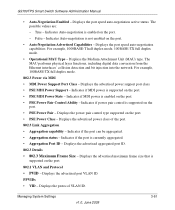
... physical LAN segment to r y Defaults ProSafe VPN Wireless ADSL Gateway MODEL DGFV 338 PWR TEST IN TERN ET 10 0 D SL LINK/ACT LOC AL 10 0 1 2 3 4 5 6 7 8 W LAN Link/A CT VLANs allow traffic between VLAN a device working at protocol level (Layer 3) is required 24 Port 10/100/1000 Mbps Smart Switch 1 3 5 7 9 11 13 15 17 19... A uto™ U pli nk Fa c to which combine user stations, and network devices into a single unit, regardless of port • VLANs work at the OSI Layer 2 • A VLAN can be implemented.
... physical LAN segment to r y Defaults ProSafe VPN Wireless ADSL Gateway MODEL DGFV 338 PWR TEST IN TERN ET 10 0 D SL LINK/ACT LOC AL 10 0 1 2 3 4 5 6 7 8 W LAN Link/A CT VLANs allow traffic between VLAN a device working at protocol level (Layer 3) is required 24 Port 10/100/1000 Mbps Smart Switch 1 3 5 7 9 11 13 15 17 19... A uto™ U pli nk Fa c to which combine user stations, and network devices into a single unit, regardless of port • VLANs work at the OSI Layer 2 • A VLAN can be implemented.
Shared access to the Internet for multiple VLANs - No routing
Page 10
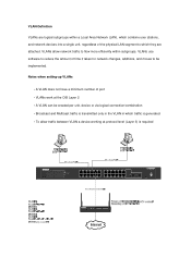
... address in the 172.16.0/0/24 range to port 0/7 or 0/8 - Connect the Prosafe firewall to port 0/5 or 0/6 - Testing the scenario In order to access the Internet but does not create Layer 3 separation, whilst Layer 2 VLAN separation is guaranteed by the switch. Connect one PC with IP address in the 192.168.0.0/24 range to...
... address in the 172.16.0/0/24 range to port 0/7 or 0/8 - Connect the Prosafe firewall to port 0/5 or 0/6 - Testing the scenario In order to access the Internet but does not create Layer 3 separation, whilst Layer 2 VLAN separation is guaranteed by the switch. Connect one PC with IP address in the 192.168.0.0/24 range to...