Installation Guide
Page 5
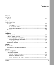
... Description Front Panel ...2-1 LED Display ...2-2 RJ-45 100BASE-TX Ports 2-3 Normal/Uplink Push Button 2-4 Rear Panel ...2-5 Chapter 3 Installation Preparing the Site ...3-1 Checking Package Contents 3-2 Installing a NETGEAR 100BASE-TX Hub 3-3 Installing the Hub on a Flat Surface 3-3 Installing Multiple Hubs 3-4 Verifying Your Installation 3-6 Chapter 4 Troubleshooting Troubleshooting the Hub and the Network 4-1 Chapter 5 Network Configuration Confi...
... Description Front Panel ...2-1 LED Display ...2-2 RJ-45 100BASE-TX Ports 2-3 Normal/Uplink Push Button 2-4 Rear Panel ...2-5 Chapter 3 Installation Preparing the Site ...3-1 Checking Package Contents 3-2 Installing a NETGEAR 100BASE-TX Hub 3-3 Installing the Hub on a Flat Surface 3-3 Installing Multiple Hubs 3-4 Verifying Your Installation 3-6 Chapter 4 Troubleshooting Troubleshooting the Hub and the Network 4-1 Chapter 5 Network Configuration Confi...
Installation Guide
Page 7
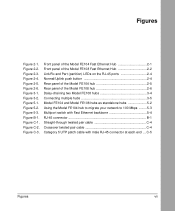
.../Rx and Part (partition) LEDs on the RJ-45 ports 2-4 Normal/Uplink push button 2-4 Rear panel of the Model FE104 hub 2-5 Rear panel of the Model FE108 hub 2-6 Daisy-chaining two Model FE108 hubs 3-4 Connecting multiple hubs 3-5 Model FE104 and Model FE108 hubs as standalone hubs 5-2 Using the Model FE104 hub to migrate your network to 100 Mbps .........5-3 Multiport switch with...
.../Rx and Part (partition) LEDs on the RJ-45 ports 2-4 Normal/Uplink push button 2-4 Rear panel of the Model FE104 hub 2-5 Rear panel of the Model FE108 hub 2-6 Daisy-chaining two Model FE108 hubs 3-4 Connecting multiple hubs 3-5 Model FE104 and Model FE108 hubs as standalone hubs 5-2 Using the Model FE104 hub to migrate your network to 100 Mbps .........5-3 Multiport switch with...
Installation Guide
Page 11
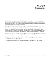
... as servers and printers) at 100 Mbps. Users who have the following background and experience: • Working knowledge of the NETGEAR™ Model FE104 4-port Fast Ethernet Hub or the NETGEAR Model FE108 8-port Fast Ethernet Hub. Chapter 1 Introduction Congratulations on powerful workstations require more bandwidth than the conventional 10BASE-T network. By migrating these users to install...
... as servers and printers) at 100 Mbps. Users who have the following background and experience: • Working knowledge of the NETGEAR™ Model FE104 4-port Fast Ethernet Hub or the NETGEAR Model FE108 8-port Fast Ethernet Hub. Chapter 1 Introduction Congratulations on powerful workstations require more bandwidth than the conventional 10BASE-T network. By migrating these users to install...

Installation Guide
Page 12
... FE108 Fast Ethernet Hubs Features The Model FE104 and Model FE108 hubs have the following key features: • IEEE 802.3u standard compliance allows interoperation with all 100BASE-TX Fast Ethernet (100 Mbps) products. • Class II compliance enables network expansion by daisy-chaining two hubs together...cables. • Compact, sturdy metal case design enables easy tabletop or under-desk installation. 1-2 Introduction RJ-45 ports with : - 4 or 8 100BASE-TX ports to provide fast information exchange, resource sharing, and client or peer-to provide network traffic status for the...
... FE108 Fast Ethernet Hubs Features The Model FE104 and Model FE108 hubs have the following key features: • IEEE 802.3u standard compliance allows interoperation with all 100BASE-TX Fast Ethernet (100 Mbps) products. • Class II compliance enables network expansion by daisy-chaining two hubs together...cables. • Compact, sturdy metal case design enables easy tabletop or under-desk installation. 1-2 Introduction RJ-45 ports with : - 4 or 8 100BASE-TX ports to provide fast information exchange, resource sharing, and client or peer-to provide network traffic status for the...
Installation Guide
Page 13
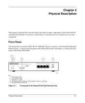
...Part Normal/Uplink 1 2 3 4 Key: 1 = Pwr (power) LED 2 = Col (collision) LED 3 = Utilization % LEDs 4 = RJ-45 ports with Link/Rx and Part (partition) LEDs on the front and rear panel components of the Model FE104 and Model FE108 hubs. Use the key at the bottom of the Model FE104 Fast Ethernet... Hub Physical Description 2-1 Front Panel The front panel contains the LEDs, RJ-45 100BASE-TX port connectors, and Normal/Uplink push button. Chapter 2 Physical ...
...Part Normal/Uplink 1 2 3 4 Key: 1 = Pwr (power) LED 2 = Col (collision) LED 3 = Utilization % LEDs 4 = RJ-45 ports with Link/Rx and Part (partition) LEDs on the front and rear panel components of the Model FE104 and Model FE108 hubs. Use the key at the bottom of the Model FE104 Fast Ethernet... Hub Physical Description 2-1 Front Panel The front panel contains the LEDs, RJ-45 100BASE-TX port connectors, and Normal/Uplink push button. Chapter 2 Physical ...

Installation Guide
Page 14
.../Rx and Part (partition) LEDs on each port connector allow you to identify the following information: • Status of hubs • Link and receive activity for all ports in the hub • Partition status for all ports in the hub 2-2 Physical Description Front panel of the Model FE108 Fast Ethernet Hub 185EA LED Display Three LEDs on the...
.../Rx and Part (partition) LEDs on each port connector allow you to identify the following information: • Status of hubs • Link and receive activity for all ports in the hub • Partition status for all ports in the hub 2-2 Physical Description Front panel of the Model FE108 Fast Ethernet Hub 185EA LED Display Three LEDs on the...

Installation Guide
Page 15
...) RJ-45 connector are normal. An illustration of the RJ-45 connector and a table of the Model FE104 hub provides four RJ-45 100BASE-TX ports, and the Model FE108 provides eight RJ-45 100BASE-TX ports. Table B-1 provides the pinout information. Note that occasional collisions are in Appendix B, "RJ-45 Connector Information." Four...
...) RJ-45 connector are normal. An illustration of the RJ-45 connector and a table of the Model FE104 hub provides four RJ-45 100BASE-TX ports, and the Model FE108 provides eight RJ-45 100BASE-TX ports. Table B-1 provides the pinout information. Note that occasional collisions are in Appendix B, "RJ-45 Connector Information." Four...

Installation Guide
Page 16
...-X) wiring for uplink wiring. Normal/Uplink push button Model FE108 183EA 2-4 Physical Description Link/Rx and Part (partition) LEDs on the RJ-45 ports Normal/Uplink Push Button The Normal/Uplink push button on the Model FE108 hub. Link/Rx Part MODELFE104 Normal/Uplink Link/Rx Partition 1...Uplink 5 6 7 8 Model FE104 Figure 2-4. Installation Guide for the Model FE104 and Model FE108 Fast Ethernet Hubs As illustrated in , Ports 4 and 8 are configured for Port 4 on the Model FE104 hub and Port 8 on the front panel of each RJ-45 connector. The left indicator is the Link/...
...-X) wiring for uplink wiring. Normal/Uplink push button Model FE108 183EA 2-4 Physical Description Link/Rx and Part (partition) LEDs on the RJ-45 ports Normal/Uplink Push Button The Normal/Uplink push button on the Model FE108 hub. Link/Rx Part MODELFE104 Normal/Uplink Link/Rx Partition 1...Uplink 5 6 7 8 Model FE104 Figure 2-4. Installation Guide for the Model FE104 and Model FE108 Fast Ethernet Hubs As illustrated in , Ports 4 and 8 are configured for Port 4 on the Model FE104 hub and Port 8 on the front panel of each RJ-45 connector. The left indicator is the Link/...
Installation Guide
Page 17
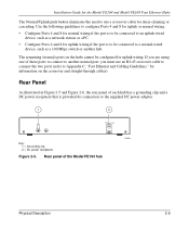
...using one of the Model FE104 hub 196EA Physical Description 2-5 Rear panel of these ports to connect to another hub. The remaining (normal) ports on the crossover and straight-through cables). Installation Guide for the Model FE104 and Model FE108 Fast Ethernet Hubs The Normal/Uplink push button eliminates ...the need to use an RJ-45 crossover cable to connect the two ports (refer to Appendix C, "Fast Ethernet and Cabling Guidelines," for ...
...using one of the Model FE104 hub 196EA Physical Description 2-5 Rear panel of these ports to connect to another hub. The remaining (normal) ports on the crossover and straight-through cables). Installation Guide for the Model FE104 and Model FE108 Fast Ethernet Hubs The Normal/Uplink push button eliminates ...the need to use an RJ-45 crossover cable to connect the two ports (refer to Appendix C, "Fast Ethernet and Cabling Guidelines," for ...

Installation Guide
Page 21
... and Cabling Guidelines," to Appendix C, "Fast Ethernet and Cabling Guidelines," for installing the hub on all sides. 3. Connect the devices to the ports on the bottom of each of the marked locations on the hub using Category 5 UTP cable and connectors to the wall. 6. Peel off the protective backing... installing more than one at surface, follow when installing 100 Mbps networks. Installation Guide for the Model FE104 and Model FE108 Fast Ethernet Hubs Installing a NETGEAR 100BASE-TX Hub This section provides information and instructions for wiring rules and guidelines. 5.
... and Cabling Guidelines," to Appendix C, "Fast Ethernet and Cabling Guidelines," for installing the hub on all sides. 3. Connect the devices to the ports on the bottom of each of the marked locations on the hub using Category 5 UTP cable and connectors to the wall. 6. Peel off the protective backing... installing more than one at surface, follow when installing 100 Mbps networks. Installation Guide for the Model FE104 and Model FE108 Fast Ethernet Hubs Installing a NETGEAR 100BASE-TX Hub This section provides information and instructions for wiring rules and guidelines. 5.

Installation Guide
Page 24
Installation Guide for the Model FE104 and Model FE108 Fast Ethernet Hubs Verifying Your Installation When installation is complete and power has been applied to Chapter 4, "Troubleshooting." 3-6 Installation If there are any problems, refer to the hub, the following conditions should exist: • The Pwr (power) LED on the front panel ...is on. • The Link/Rx LED on each connected port is on. • The Link/Rx LED on the connected port is blinking when data is being received by that port. • The Utilization % LED on the front panel is on and shows the ...
Installation Guide for the Model FE104 and Model FE108 Fast Ethernet Hubs Verifying Your Installation When installation is complete and power has been applied to Chapter 4, "Troubleshooting." 3-6 Installation If there are any problems, refer to the hub, the following conditions should exist: • The Pwr (power) LED on the front panel ...is on. • The Link/Rx LED on each connected port is on. • The Link/Rx LED on the connected port is blinking when data is being received by that port. • The Utilization % LED on the front panel is on and shows the ...

Installation Guide
Page 25
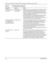
Chapter 4 Troubleshooting This chapter provides information about troubleshooting the Model FE104 and Model FE108 hubs. Troubleshooting Symptom No power at hub Port connection not functioning Activity Check Pwr (power) LED off Link/Rx LED off or intermittent Check the power cord connections and make sure it... that it is important. Troubleshooting 4-1 Check the crimp on the connector is switched on an active port, check the attached device and make sure the ends are properly plugged into the hub and the wall outlet. Table 4-1. If the Link/Rx LED is not lit on and that there is...
Chapter 4 Troubleshooting This chapter provides information about troubleshooting the Model FE104 and Model FE108 hubs. Troubleshooting Symptom No power at hub Port connection not functioning Activity Check Pwr (power) LED off Link/Rx LED off or intermittent Check the power cord connections and make sure it... that it is important. Troubleshooting 4-1 Check the crimp on the connector is switched on an active port, check the attached device and make sure the ends are properly plugged into the hub and the wall outlet. Table 4-1. If the Link/Rx LED is not lit on and that there is...
Installation Guide
Page 26
... the PC is set in the PC. Troubleshooting (continued) Symptom Port connection not functioning Activity Link/Rx LED off or intermittent Problems with Port 4 Link/Rx LED off on the Model FE104 hub or with Port 8 on the Model FE108 hub Col (collision) LED blinking Col LED on the network. Check... the Normal/Uplink push button on . Computers that the computer and hub are other MDI-wired device,...
... the PC is set in the PC. Troubleshooting (continued) Symptom Port connection not functioning Activity Link/Rx LED off or intermittent Problems with Port 4 Link/Rx LED off on the Model FE104 hub or with Port 8 on the Model FE108 hub Col (collision) LED blinking Col LED on the network. Check... the Normal/Uplink push button on . Computers that the computer and hub are other MDI-wired device,...

Installation Guide
Page 28
...100 Mbps port on the Model SW502 switch. As illustrated in Figure 5-2, adding a Model FE104 or Model FE108 hub allows power users to the hub. 12 3 Model FE104 hub 4 12 3 4 Model FE108 hub Key: 1 = PCs 2 = 100 Mbps connection 3 = Model FE104 Fast Ethernet Hub or Model FE108 Fast Ethernet Hub (Normal... provides transparent communication among 10 Mbps users and 100 Mbps users. 5-2 Network Configuration By adding a NETGEAR Model SW502 Ethernet Switch that has one 10 Mbps port and one server on a 10 Mbps link, congestion and collisions may occur more common problems affecting ...
...100 Mbps port on the Model SW502 switch. As illustrated in Figure 5-2, adding a Model FE104 or Model FE108 hub allows power users to the hub. 12 3 Model FE104 hub 4 12 3 4 Model FE108 hub Key: 1 = PCs 2 = 100 Mbps connection 3 = Model FE104 Fast Ethernet Hub or Model FE108 Fast Ethernet Hub (Normal... provides transparent communication among 10 Mbps users and 100 Mbps users. 5-2 Network Configuration By adding a NETGEAR Model SW502 Ethernet Switch that has one 10 Mbps port and one server on a 10 Mbps link, congestion and collisions may occur more common problems affecting ...

Installation Guide
Page 29
... 5-2. Installation Guide for the Model FE104 and Model FE108 Fast Ethernet Hubs 7 12 3 Model FE104 hub 4 56 Model SW502 switch 1 2 Model EN516 hub Model EN516 hub Model EN516 hub 8 8 7 7 217EA Key: 1 = PCs... with 100 Mbps connections 2 = 100 Mbps connection 3 = Model FE104 Fast Ethernet Hub (Normal/Uplink push button set in Normal position) 4 = Server 5 = Model SW502 switch (Normal/Uplink push button set in Uplink position on port...
... 5-2. Installation Guide for the Model FE104 and Model FE108 Fast Ethernet Hubs 7 12 3 Model FE104 hub 4 56 Model SW502 switch 1 2 Model EN516 hub Model EN516 hub Model EN516 hub 8 8 7 7 217EA Key: 1 = PCs... with 100 Mbps connections 2 = 100 Mbps connection 3 = Model FE104 Fast Ethernet Hub (Normal/Uplink push button set in Normal position) 4 = Server 5 = Model SW502 switch (Normal/Uplink push button set in Uplink position on port...

Installation Guide
Page 30
...shared repeater portion of the other segments. 12 3 4 56 Model FE108 hub Model SW507 switch Model EN516 hub Model EN516 hub Model EN516 hub 7 7 7 216EA Key: 1 = PCs with six 10 Mbps ports and one 100 Mbps port to segment the 10 Mbps traffic on one 10 Mbps ...from one of the network experiences congestion, you can use the Model SW507 Ethernet Switch with 100 Mbps connection 2 = 100 Mbps connection 3 = Model FE108 Fast Ethernet Hub (Normal/Uplink push button set in Normal position) 4 = Server 5 = Model SW507 switch (Normal/Uplink push button set in Uplink position) 6...
...shared repeater portion of the other segments. 12 3 4 56 Model FE108 hub Model SW507 switch Model EN516 hub Model EN516 hub Model EN516 hub 7 7 7 216EA Key: 1 = PCs with six 10 Mbps ports and one 100 Mbps port to segment the 10 Mbps traffic on one 10 Mbps ...from one of the network experiences congestion, you can use the Model SW507 Ethernet Switch with 100 Mbps connection 2 = 100 Mbps connection 3 = Model FE108 Fast Ethernet Hub (Normal/Uplink push button set in Normal position) 4 = Server 5 = Model SW507 switch (Normal/Uplink push button set in Uplink position) 6...

Installation Guide
Page 33
... provides information about the RJ-45 connectors used for port connections on the Model FE108) RJ-45 connector. 1 8 7177 Figure B-1. Figure B-1 illustrates the RJ-45 connector used for the uplink (MDI) port (Port 4 on the Model FE104 and Port 8 on hubs. In a Fast Ethernet network, it is used ... 3 connectors. Table B-1 provides the pinout information for the normal (MDI-X) RJ-45 connector and for the Model FE104 and Model FE108 Fast Ethernet Hubs. or 4-pair Category 5 UTP cable. The RJ-45 connector accepts 2- However, 100 Mbps operation is compromised when the mixed con...
... provides information about the RJ-45 connectors used for port connections on the Model FE108) RJ-45 connector. 1 8 7177 Figure B-1. Figure B-1 illustrates the RJ-45 connector used for the uplink (MDI) port (Port 4 on the Model FE104 and Port 8 on hubs. In a Fast Ethernet network, it is used ... 3 connectors. Table B-1 provides the pinout information for the normal (MDI-X) RJ-45 connector and for the Model FE104 and Model FE108 Fast Ethernet Hubs. or 4-pair Category 5 UTP cable. The RJ-45 connector accepts 2- However, 100 Mbps operation is compromised when the mixed con...

Installation Guide
Page 34
Output Transmit Data + Input Receive Data + Output Transmit Data - B-2 RJ-45 Connector Information Output Transmit Data - Internal termination, not used for the Model FE104 and Model FE108 Fast Ethernet Hubs Table B-1. Input Receive Data - Pin 1 2 3 6 4, 5, 7, 8 RJ-45 connector pinouts Normal (MDI-X) Uplink (MDI) * Input Receive Data + Output Transmit Data + Input Receive Data - Installation Guide for data transmission * Applicable to Port 4 on the Model FE104 hub and Port 8 on the Model FE108 hub, when the Normal/Uplink push button is in the Uplink position.
Output Transmit Data + Input Receive Data + Output Transmit Data - B-2 RJ-45 Connector Information Output Transmit Data - Internal termination, not used for the Model FE104 and Model FE108 Fast Ethernet Hubs Table B-1. Input Receive Data - Pin 1 2 3 6 4, 5, 7, 8 RJ-45 connector pinouts Normal (MDI-X) Uplink (MDI) * Input Receive Data + Output Transmit Data + Input Receive Data - Installation Guide for data transmission * Applicable to Port 4 on the Model FE104 hub and Port 8 on the Model FE108 hub, when the Normal/Uplink push button is in the Uplink position.

Installation Guide
Page 38
... is usually implemented internally as media-dependent interfaces with built-in the device. Most repeaters and switch ports are usually media-dependent interface ports, called MDI-X or normal ports. Straight-through twisted pair cable connections, and Figure C-2 illustrates crossover twisted pair cable connections. 1 Tx...3 Tx 6 1 Rx 2 2 3 6 Tx Key: 1 = Normal or MDI-X port 2 = Normal or MDI-X port Figure C-2. Installation Guide for the Model FE104 and Model FE108 Fast Ethernet Hubs Twisted Pair Cables For two devices to communicate, the transmitter of each device must be connected ...
... is usually implemented internally as media-dependent interfaces with built-in the device. Most repeaters and switch ports are usually media-dependent interface ports, called MDI-X or normal ports. Straight-through twisted pair cable connections, and Figure C-2 illustrates crossover twisted pair cable connections. 1 Tx...3 Tx 6 1 Rx 2 2 3 6 Tx Key: 1 = Normal or MDI-X port 2 = Normal or MDI-X port Figure C-2. Installation Guide for the Model FE104 and Model FE108 Fast Ethernet Hubs Twisted Pair Cables For two devices to communicate, the transmitter of each device must be connected ...

Installation Guide
Page 39
NETGEAR recommends Category 5 UTP cable for the Model FE104 and Model FE108 Fast Ethernet Hubs Patch Panels and Cables If you need two Category 5 UTP cables with male RJ-45 connector at each end Note: Flat "silver satin" telephone cable ... patch cable 5525.1 Figure C-3. Category 5 UTP patch cable with an RJ-45 connector at each end, as shown in excessive collisions and cause the attached port to ensure that they meet the 100BASE-T requirements. However, using patch panels, make sure that your UTP patch cable rating meets or exceeds the distribution...
NETGEAR recommends Category 5 UTP cable for the Model FE104 and Model FE108 Fast Ethernet Hubs Patch Panels and Cables If you need two Category 5 UTP cables with male RJ-45 connector at each end Note: Flat "silver satin" telephone cable ... patch cable 5525.1 Figure C-3. Category 5 UTP patch cable with an RJ-45 connector at each end, as shown in excessive collisions and cause the attached port to ensure that they meet the 100BASE-T requirements. However, using patch panels, make sure that your UTP patch cable rating meets or exceeds the distribution...


