

Installation Guide
Page 1
... Power Consumption (Typical) Power Consumption (Max Brightness) Power Consumption (Overall Max)* BTU's (Typical) BTU's (Max Brightness) BTU's (Overall Max)* Net Dimensions Net Weight V554 P554 1920 x 1080 at 60Hz 3840 x 2160 at max brightness and the following features are also active: OPS Slot, External Speaker, Raspberry Pi Compute Module...support the monitor and the installation must be strong enough to supply useful information for portrait orientation. Rotate only clockwise for a design or installation. V554/P554 Installation Guide 55" LCD Display NEC Display Solutions of 10
... Power Consumption (Typical) Power Consumption (Max Brightness) Power Consumption (Overall Max)* BTU's (Typical) BTU's (Max Brightness) BTU's (Overall Max)* Net Dimensions Net Weight V554 P554 1920 x 1080 at 60Hz 3840 x 2160 at max brightness and the following features are also active: OPS Slot, External Speaker, Raspberry Pi Compute Module...support the monitor and the installation must be strong enough to supply useful information for portrait orientation. Rotate only clockwise for a design or installation. V554/P554 Installation Guide 55" LCD Display NEC Display Solutions of 10

Installation Guide
Page 2
Rev 1.0 Ventilation Recommendations: Dimensions below are recommended for design review and recommendations. If for some reason the opening . www.necdisplay.com V554/P554 Page 2 of America, Inc. NOTE: The ventilation space should not be covered or closed off at the front of the opening needs to be covered, other means of ventilation will need to be incorporated into the design. V554/P554 Installation Guide 55" LCD Display NEC Display Solutions of 10 Contact NEC for proper ventilation when the unit is in a recessed area.
Rev 1.0 Ventilation Recommendations: Dimensions below are recommended for design review and recommendations. If for some reason the opening . www.necdisplay.com V554/P554 Page 2 of America, Inc. NOTE: The ventilation space should not be covered or closed off at the front of the opening needs to be covered, other means of ventilation will need to be incorporated into the design. V554/P554 Installation Guide 55" LCD Display NEC Display Solutions of 10 Contact NEC for proper ventilation when the unit is in a recessed area.

Installation Guide
Page 3
Rev 1.0 www.necdisplay.com V554/P554 Page 3 of America, Inc. V554/P554 Installation Guide 55" LCD Display Display dimensions: NEC Display Solutions of 10
Rev 1.0 www.necdisplay.com V554/P554 Page 3 of America, Inc. V554/P554 Installation Guide 55" LCD Display Display dimensions: NEC Display Solutions of 10

Installation Guide
Page 4
Rev 1.0 www.necdisplay.com V554/P554 Page 4 of America, Inc. V554/P554 Installation Guide 55" LCD Display Display dimensions (cont.): NEC Display Solutions of 10
Rev 1.0 www.necdisplay.com V554/P554 Page 4 of America, Inc. V554/P554 Installation Guide 55" LCD Display Display dimensions (cont.): NEC Display Solutions of 10

Installation Guide
Page 5
V554/P554 Installation Guide 55" LCD Display Display Dimensions (with ST-401 stand): NEC Display Solutions of 10 Rev 1.0 NOTE: The ST-401 optional stand attaches to the VESA hole pattern on the back of the display and can be set so the display is either 30mm or 50mm from the tabletop www.necdisplay.com V554/P554 Page 5 of America, Inc.
V554/P554 Installation Guide 55" LCD Display Display Dimensions (with ST-401 stand): NEC Display Solutions of 10 Rev 1.0 NOTE: The ST-401 optional stand attaches to the VESA hole pattern on the back of the display and can be set so the display is either 30mm or 50mm from the tabletop www.necdisplay.com V554/P554 Page 5 of America, Inc.

Installation Guide
Page 6
V554/P554 Installation Guide 55" LCD Display Optional Table Top Stand Dimensions (ST-401): NEC Display Solutions of the display. Rev 1.0 NOTE: The Pole of the ST-401 stand connects directly to the VESA hole pattern on the back of America, Inc. www.necdisplay.com V554/P554 Page 6 of 10
V554/P554 Installation Guide 55" LCD Display Optional Table Top Stand Dimensions (ST-401): NEC Display Solutions of the display. Rev 1.0 NOTE: The Pole of the ST-401 stand connects directly to the VESA hole pattern on the back of America, Inc. www.necdisplay.com V554/P554 Page 6 of 10

Installation Guide
Page 7
Rev 1.0 Dimensions of Optional Wall Mount Kit (WMK-4655S): www.necdisplay.com V554/P554 Page 7 of America, Inc. V554/P554 Installation Guide 55" LCD Display NEC Display Solutions of 10
Rev 1.0 Dimensions of Optional Wall Mount Kit (WMK-4655S): www.necdisplay.com V554/P554 Page 7 of America, Inc. V554/P554 Installation Guide 55" LCD Display NEC Display Solutions of 10

Installation Guide
Page 8
Rev 1.0 Compute Module Integration: • Door on the back of the display can be opened by loosening captive screws. • Separate IO Board is necessary to accompany RPi Compute Module in unit www.necdisplay.com V554/P554 Page 8 of America, Inc. V554/P554 Installation Guide 55" LCD Display NEC Display Solutions of 10
Rev 1.0 Compute Module Integration: • Door on the back of the display can be opened by loosening captive screws. • Separate IO Board is necessary to accompany RPi Compute Module in unit www.necdisplay.com V554/P554 Page 8 of America, Inc. V554/P554 Installation Guide 55" LCD Display NEC Display Solutions of 10

Installation Guide
Page 9
... Used Not Used NOTE: If so desired, jumper "Request to send" and "Clear to simplify cable connection. These connections are pins 2 (TxD), 3 (RxD) and 5 (GND). V554/P554 Installation Guide 55" LCD Display Control Codes: NEC Display Solutions of the cable to Send" together on both ends of America, Inc. Rev 1.0 NOTE: Contact your...
... Used Not Used NOTE: If so desired, jumper "Request to send" and "Clear to simplify cable connection. These connections are pins 2 (TxD), 3 (RxD) and 5 (GND). V554/P554 Installation Guide 55" LCD Display Control Codes: NEC Display Solutions of the cable to Send" together on both ends of America, Inc. Rev 1.0 NOTE: Contact your...

Installation Guide
Page 10
Rotated) Browser Control Information and control can also be available through the HTTP browser control menu. Rev 1.0 Input Panel (Side - In order to accomplish this, type: http:// V554/P554 Installation Guide 55" LCD Display Input Panel (Bottom) NEC Display Solutions of America, Inc.
Rotated) Browser Control Information and control can also be available through the HTTP browser control menu. Rev 1.0 Input Panel (Side - In order to accomplish this, type: http:// V554/P554 Installation Guide 55" LCD Display Input Panel (Bottom) NEC Display Solutions of America, Inc.
External Controls
Page 1
... Timing Report and Timing reply 20 5.5.3 NULL Message...21 IV. How to read the measurement value of the built-in temperature sensors 25 6.3. External Control NEC LCD Monitor INDEX Rev.1.7 (G4) I.
... Timing Report and Timing reply 20 5.5.3 NULL Message...21 IV. How to read the measurement value of the built-in temperature sensors 25 6.3. External Control NEC LCD Monitor INDEX Rev.1.7 (G4) I.
External Controls
Page 4
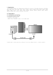
Application This document defines the communications method for control of the NEC LCD monitor, MultiSync P404 /P484 /P554 /V404 /V484 /V554/ V404-T/ V484-T/ V554-T/ P654Q/ P754Q/ V554Q/ V654Q/ V754Q/ V864Q/ V984Q/ C651Q/ C751Q/ C861Q/ C981Q/ UN462A/ UN462VA/ UN492S/ UN492VS/ UN552/ UN552V/ UN552S/ UN552VS when using an external controller. Preparation 2. I. II. Connectors and wiring 2.1 RS-232C Remote control Connector: 9-pin D-Sub Cable: Cross (reversed) cable or null modem cable (Please refer "Controlling the LCD monitor via RS-232C Remote control" on User's manual.) (4/145)
Application This document defines the communications method for control of the NEC LCD monitor, MultiSync P404 /P484 /P554 /V404 /V484 /V554/ V404-T/ V484-T/ V554-T/ P654Q/ P754Q/ V554Q/ V654Q/ V754Q/ V864Q/ V984Q/ C651Q/ C751Q/ C861Q/ C981Q/ UN462A/ UN462VA/ UN492S/ UN492VS/ UN552/ UN552V/ UN552S/ UN552VS when using an external controller. Preparation 2. I. II. Connectors and wiring 2.1 RS-232C Remote control Connector: 9-pin D-Sub Cable: Cross (reversed) cable or null modem cable (Please refer "Controlling the LCD monitor via RS-232C Remote control" on User's manual.) (4/145)
External Controls
Page 5
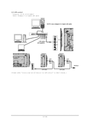
2.2 LAN control Connector: RJ-45 10/100 BASE-T Cable: Category 5 or higher LAN cable (Please refer "Controlling the LCD monitor via LAN control" on User's manual.) (5/145)
2.2 LAN control Connector: RJ-45 10/100 BASE-T Cable: Category 5 or higher LAN cable (Please refer "Controlling the LCD monitor via LAN control" on User's manual.) (5/145)

User Manual
Page 2
V554-T...English-67 Manufacturer's Recycling and Energy Information English-68 [Notice] About the MPEG-4 AVC, MPEG‑4 Visual license included in Picture) ...-2 WARNING...English-2 CAUTION...English-2 Safety Precautions, Maintenance & Recommended Use English-3 Safety Precautions and Maintenance...English-3 Recommended Use...English-3 Ergonomics...English-3 Cleaning the LCD Panel...English-4 Cleaning the Cabinet...English-4 Installation...English-5 Attaching Mounting Accessories...English-7 Parts Name and Functions...English-9 Control Panel...English-9 Terminal Panel...English-10 Wireless...
V554-T...English-67 Manufacturer's Recycling and Energy Information English-68 [Notice] About the MPEG-4 AVC, MPEG‑4 Visual license included in Picture) ...-2 WARNING...English-2 CAUTION...English-2 Safety Precautions, Maintenance & Recommended Use English-3 Safety Precautions and Maintenance...English-3 Recommended Use...English-3 Ergonomics...English-3 Cleaning the LCD Panel...English-4 Cleaning the Cabinet...English-4 Installation...English-5 Attaching Mounting Accessories...English-7 Parts Name and Functions...English-9 Control Panel...English-9 Terminal Panel...English-10 Wireless...

User Manual
Page 6
... material. • Please do not apply pressure to deteriorate, crack or peel. Cleaning the LCD Panel • When the LCD panel is dusty, please gently wipe with a soft cloth. • Clean the LCD monitor surface with the cabinet for an extended period of fluids and materials can cause the paint... to the LCD panel surface. • Please do not use OA cleaner as it will cause deterioration or discoloration on the LCD panel surface. English-4 Rubber or vinyl should not be in contact with a lint-free...
... material. • Please do not apply pressure to deteriorate, crack or peel. Cleaning the LCD Panel • When the LCD panel is dusty, please gently wipe with a soft cloth. • Clean the LCD monitor surface with the cabinet for an extended period of fluids and materials can cause the paint... to the LCD panel surface. • Please do not use OA cleaner as it will cause deterioration or discoloration on the LCD panel surface. English-4 Rubber or vinyl should not be in contact with a lint-free...

User Manual
Page 7
...enough to support the weight of the unit so that it . The monitor must be safe from the wall or ceiling, NEC strongly recommends using a wire. • Please install LCD monitor in the box. Bracket No thread 4 mm 10-12 mm Washers Screw Thickness of bracket and washers hole should ...time, slight expansion of the monitors may cause the monitor to become distorted or damaged. • To prevent the LCD monitor from falling off from the wall or ceiling, NEC strongly recommends using an installation safety wire. Mounting on it is no speakers installed Please use two or more brackets to...
...enough to support the weight of the unit so that it . The monitor must be safe from the wall or ceiling, NEC strongly recommends using a wire. • Please install LCD monitor in the box. Bracket No thread 4 mm 10-12 mm Washers Screw Thickness of bracket and washers hole should ...time, slight expansion of the monitors may cause the monitor to become distorted or damaged. • To prevent the LCD monitor from falling off from the wall or ceiling, NEC strongly recommends using an installation safety wire. Mounting on it is no speakers installed Please use two or more brackets to...

User Manual
Page 8
... enough to support the weight of the unit and the mounting equipment over time. 3.6 mm LED Indicator Changing NEC logo ornament position When using the monitor in the bottom of the LCD monitor: Orientation • When using the monitor in . 2 mm English-6 Attaching the logo ornament: Hook ...changed. Removing the logo ornament: Insert a thin stick (less than 3 mm diameter) into the bezel and press in the portrait position, the NEC logo ornament position can easily grab and hang onto the unit or the mounting equipment. • Allow for loose screws, gaps, distortions, or...
... enough to support the weight of the unit and the mounting equipment over time. 3.6 mm LED Indicator Changing NEC logo ornament position When using the monitor in the bottom of the LCD monitor: Orientation • When using the monitor in . 2 mm English-6 Attaching the logo ornament: Hook ...changed. Removing the logo ornament: Insert a thin stick (less than 3 mm diameter) into the bezel and press in the portrait position, the NEC logo ornament position can easily grab and hang onto the unit or the mounting equipment. • Allow for loose screws, gaps, distortions, or...

User Manual
Page 9
... you to avoid tipping the monitor when attaching accessories. Turn off the main power switch. 2. VESA Mounting Interface (M6) 4. Make sure that is larger than NEC compliant and approved, they must comply with adequate space. 2. 300 mm English Attaching Mounting Accessories The monitor is inserted into the monitor and fix it...
... you to avoid tipping the monitor when attaching accessories. Turn off the main power switch. 2. VESA Mounting Interface (M6) 4. Make sure that is larger than NEC compliant and approved, they must comply with adequate space. 2. 300 mm English Attaching Mounting Accessories The monitor is inserted into the monitor and fix it...

User Manual
Page 10
4. NOTE: ONLY use this monitor on the acoustics of the height adjustment (Figure 3). When installing the LCD monitor stand, handle the unit with included screws. Please use screws which are supplied with the optional table top stand. Please adjust the pipe to ... around the monitor, so that heat can cause tipping. When the monitor is moved after the stands are indicators of the room. 100 mm Pipe V554-T V484-T V404-T Adjust the pipe to the ST-401 user's manual for support. It may cause damage to the lines. 100 mm 5. The lines on...
4. NOTE: ONLY use this monitor on the acoustics of the height adjustment (Figure 3). When installing the LCD monitor stand, handle the unit with included screws. Please use screws which are supplied with the optional table top stand. Please adjust the pipe to ... around the monitor, so that heat can cause tipping. When the monitor is moved after the stands are indicators of the room. 100 mm Pipe V554-T V484-T V404-T Adjust the pipe to the ST-401 user's manual for support. It may cause damage to the lines. 100 mm 5. The lines on...

User Manual
Page 11
Acts as a "set button" when you make automatic adjustments to decrease the adjustment within OSD menu. Glows blue when the LCD monitor is turned off . SET: When OSD (On Screen Display) is shown, this sensor. F Up Button ( ) Activates the OSD menu when the OSD menu... setting, resulting in active mode. *1 If "OFF" is turned off . Acts as a back button within the monitor, the indicator will not glow when the LCD monitor is in a more comfortable viewing experience. Acts as button to move the highlighted area up to the previous OSD menu. I Remote Control Sensor and...
Acts as a "set button" when you make automatic adjustments to decrease the adjustment within OSD menu. Glows blue when the LCD monitor is turned off . SET: When OSD (On Screen Display) is shown, this sensor. F Up Button ( ) Activates the OSD menu when the OSD menu... setting, resulting in active mode. *1 If "OFF" is turned off . Acts as a back button within the monitor, the indicator will not glow when the LCD monitor is in a more comfortable viewing experience. Acts as button to move the highlighted area up to the previous OSD menu. I Remote Control Sensor and...
