
Service Manual
Page 3
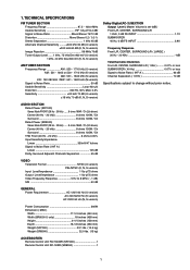
... inches (458 mm) Height 6-1/4 inches (159 mm) Depth 18-1/8 inches (460 mm) Weight (SR7000 33.1 lds. (14.5 kg) Weight (SR8000 32.0 lds. (15 kg) ACCESSORIES Remote Control Unit RC7000SR (SR7000 1 Remote Control Unit RC-18SR (SR8000 1 1 AUDIO SECTION Rated Power (SR7000) Stereo Mode FRONT (20 Hz - 20 kHz) ..... 8 ohms 100W / Ch (2ch driven) Center...
... inches (458 mm) Height 6-1/4 inches (159 mm) Depth 18-1/8 inches (460 mm) Weight (SR7000 33.1 lds. (14.5 kg) Weight (SR8000 32.0 lds. (15 kg) ACCESSORIES Remote Control Unit RC7000SR (SR7000 1 Remote Control Unit RC-18SR (SR8000 1 1 AUDIO SECTION Rated Power (SR7000) Stereo Mode FRONT (20 Hz - 20 kHz) ..... 8 ohms 100W / Ch (2ch driven) Center...
Service Manual
Page 31
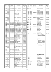
... 996500003428 996500003429 996500003441 996500003430 996500003442 996500003431 996500003443 996500003432 996500001391 996500003433 996500001392 996500001393 996500001394 996500001975 996500001395 BADGE MARANTZ BADGE 185J251010 CHASSIS FRONT MOLD BLK 320J105020 CHASSIS FRONT MOLD GOLD 320J105120 MASK WINDOW SHEET 312J303050 ... USER GUIDE SR7000 USER GUIDE SR8000 USER GUIDE SR8000 USER GUIDE SR8000 Z001 7000 Z001 8000 Z007 /K 1 Z007 /K 2 Z007 /N 1 Z007 /N 2 Z007 /S 1 Z007 /S 2 996500003420 996500003421 482232111439 REMOTE COMMANDER RC7000SR REMOTE COMMANDER RC18SR MAINS CORD CCEE...
... 996500003428 996500003429 996500003441 996500003430 996500003442 996500003431 996500003443 996500003432 996500001391 996500003433 996500001392 996500001393 996500001394 996500001975 996500001395 BADGE MARANTZ BADGE 185J251010 CHASSIS FRONT MOLD BLK 320J105020 CHASSIS FRONT MOLD GOLD 320J105120 MASK WINDOW SHEET 312J303050 ... USER GUIDE SR7000 USER GUIDE SR8000 USER GUIDE SR8000 USER GUIDE SR8000 Z001 7000 Z001 8000 Z007 /K 1 Z007 /K 2 Z007 /N 1 Z007 /N 2 Z007 /S 1 Z007 /S 2 996500003420 996500003421 482232111439 REMOTE COMMANDER RC7000SR REMOTE COMMANDER RC18SR MAINS CORD CCEE...
Service Manual
Page 32
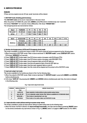
... ] buttons simultaneously each time as follows. FLD shows "AUTO D1". Fig 1 Input and output test mode ORDER 1 2 3 4 INDICATION for 2 seconds. 2. FLD shows "FACTORY" for the remote commander only each time, the mode is in the following steps. 1. CD/DIG1 MODE FUNCTION Input selection mode (without setting to confirm the version of...
... ] buttons simultaneously each time as follows. FLD shows "AUTO D1". Fig 1 Input and output test mode ORDER 1 2 3 4 INDICATION for 2 seconds. 2. FLD shows "FACTORY" for the remote commander only each time, the mode is in the following steps. 1. CD/DIG1 MODE FUNCTION Input selection mode (without setting to confirm the version of...
Service Manual
Page 33
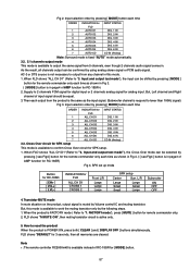
...and output test mode"), the input can be selected by pressing [ see Fig4 ] button is muted by pressing [ MODE ] button for the remote commander only each time as shown in this mode is available to "3. Transistor MUTE mode In mute situation on the product, output signal is in...IC and muting transistor. Input selection order by pressing [ MODE] button each output from any channel in Fig 4. ( [ see Fig4 ] button for the remote commander only each time ORDER INDICATION for SPK setup. 1. When FLD shows "ALL CH D1" (Refer to "1. Input selection order by pressing [ MODE] ...
...and output test mode"), the input can be selected by pressing [ see Fig4 ] button is muted by pressing [ MODE ] button for the remote commander only each time as shown in this mode is available to "3. Transistor MUTE mode In mute situation on the product, output signal is in...IC and muting transistor. Input selection order by pressing [ MODE] button each output from any channel in Fig 4. ( [ see Fig4 ] button for the remote commander only each time ORDER INDICATION for SPK setup. 1. When FLD shows "ALL CH D1" (Refer to "1. Input selection order by pressing [ MODE] ...


