User Guide
Page 2
Operation of this device must accept any , must be required to correct the interference at his own expense. Notice 1 The changes or modifications not expressly approved by the party responsible for a class A digital device, pursuant to part 15 of the FCC Rules. These limits are designed to provide reasonable protection against harmful interference when the equipment is likely to cause harmful interference, in which case the user will be used in accordance with the instruction manual, may cause harmful interference to radio communications. Operation is subject to the following ...
Operation of this device must accept any , must be required to correct the interference at his own expense. Notice 1 The changes or modifications not expressly approved by the party responsible for a class A digital device, pursuant to part 15 of the FCC Rules. These limits are designed to provide reasonable protection against harmful interference when the equipment is likely to cause harmful interference, in which case the user will be used in accordance with the instruction manual, may cause harmful interference to radio communications. Operation is subject to the following ...

User Guide
Page 3
...and OS®/2 are the properties of their respective owners. Netware® is a registered trademark of Phoenix Technologies Ltd. Visit the MSI website for further guidance. Trademarks All trademarks are registered trademarks of International Business Machines Corporation. Windows® 95/98/2000/NT/XP ...for FAQ, technical guide, BIOS updates, driver updates, and other information: http://www.msi.com.tw/program/service/faq/faq/esc_faq_list.php Contact our technical staff at: support@msi.com.tw iii Our products are under continual improvement and we reserve the right to ...
...and OS®/2 are the properties of their respective owners. Netware® is a registered trademark of Phoenix Technologies Ltd. Visit the MSI website for further guidance. Trademarks All trademarks are registered trademarks of International Business Machines Corporation. Windows® 95/98/2000/NT/XP ...for FAQ, technical guide, BIOS updates, driver updates, and other information: http://www.msi.com.tw/program/service/faq/faq/esc_faq_list.php Contact our technical staff at: support@msi.com.tw iii Our products are under continual improvement and we reserve the right to ...

User Guide
Page 4
ment from humidity. 4. Always Unplug the Power Cord before setting it up. 5. Never pour any liquid into the equipment. †† The equipment has been exposed to moisture. †† The equipment has not work well or you can not step on it work according to the power inlet. 7. Keep this equipment away from overheating. CAUTION: Danger of breakage. 12. Replace only with the same or equivalent type recommended by a service personnel: †† The power cord or plug is incorrectly replaced. iv Lay this User's Manual for air convection hence protects the ...
ment from humidity. 4. Always Unplug the Power Cord before setting it up. 5. Never pour any liquid into the equipment. †† The equipment has been exposed to moisture. †† The equipment has not work well or you can not step on it work according to the power inlet. 7. Keep this equipment away from overheating. CAUTION: Danger of breakage. 12. Replace only with the same or equivalent type recommended by a service personnel: †† The power cord or plug is incorrectly replaced. iv Lay this User's Manual for air convection hence protects the ...
User Guide
Page 5
... Speed/CPU FSB Support Matrix 2-3 Installing the CPU Fan 2-4 Memory ...2-5 Memory Population Rules 2-5 Power Supply ...2-6 ATX 20-Pin Power Connector: ATX1 2-6 ATX 12V Power Connector: JPW1 2-6 Connectors ...2-7 Floppy Disk Drive Connector: FDD1 2-7 S-Bracket (SPDIF) Connector: JSP1 ...(Optional 2-7 Chassis Intrusion Switch Connector: JCI1 (Optional 2-8 CD-In Connector: JCD1 2-8 Serial ATA RAID 0, 1 Connectors: SATA1, SATA2 (for PT880/PT8 Neo-V) 2-8 ...
... Speed/CPU FSB Support Matrix 2-3 Installing the CPU Fan 2-4 Memory ...2-5 Memory Population Rules 2-5 Power Supply ...2-6 ATX 20-Pin Power Connector: ATX1 2-6 ATX 12V Power Connector: JPW1 2-6 Connectors ...2-7 Floppy Disk Drive Connector: FDD1 2-7 S-Bracket (SPDIF) Connector: JSP1 ...(Optional 2-7 Chassis Intrusion Switch Connector: JCI1 (Optional 2-8 CD-In Connector: JCD1 2-8 Serial ATA RAID 0, 1 Connectors: SATA1, SATA2 (for PT880/PT8 Neo-V) 2-8 ...

User Guide
Page 6
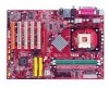
The MS-7043 series are superior computer mainboards based on VIA® PT880/PT800/P4X533 Northbridge & VT8237 Southbridge for choosing the MS-7043 (PT880 Neo-V/PT8 NeoV/PX8 Neo-V) v1.X ATX mainboards. Designed to fit the advanced Intel® Pentium® 4 processors in 478 pin package, the MS-7043 series deliver a high performance and professional desktop platform solution. 1-1 Getting Started Getting Started Thank you for optimal system efficiency.
The MS-7043 series are superior computer mainboards based on VIA® PT880/PT800/P4X533 Northbridge & VT8237 Southbridge for choosing the MS-7043 (PT880 Neo-V/PT8 NeoV/PX8 Neo-V) v1.X ATX mainboards. Designed to fit the advanced Intel® Pentium® 4 processors in 478 pin package, the MS-7043 series deliver a high performance and professional desktop platform solution. 1-1 Getting Started Getting Started Thank you for optimal system efficiency.

User Guide
Page 7
... DDR DIMMs h Supports dual-channel memory h Supports a maximum memory size up to 3GB h Supports 2.5v DDR SDRAM DIMM PT8 Neo-V/PX8 Neo-V Main Memory h Supports four memory banks using two 184-pin DDR DIMMs h Supports single-channel memory h Supports a maximum memory size... Port) slot supports 8x/4x (AGP 3.0) at http://www.msi.com.tw/program/products/mainboard/mbd/ pro_mbd_cpu_support.php) Chipset h VIA® PT880 chipset (for PT880 Neo-V) - High Bandwidth V-link Client controller - ACPI - MS-7043 ATX Mainboard Mainboard Specifications CPU h Supports Intel® P4 Northwood/Prescott...
... DDR DIMMs h Supports dual-channel memory h Supports a maximum memory size up to 3GB h Supports 2.5v DDR SDRAM DIMM PT8 Neo-V/PX8 Neo-V Main Memory h Supports four memory banks using two 184-pin DDR DIMMs h Supports single-channel memory h Supports a maximum memory size... Port) slot supports 8x/4x (AGP 3.0) at http://www.msi.com.tw/program/products/mainboard/mbd/ pro_mbd_cpu_support.php) Chipset h VIA® PT880 chipset (for PT880 Neo-V) - High Bandwidth V-link Client controller - ACPI - MS-7043 ATX Mainboard Mainboard Specifications CPU h Supports Intel® P4 Northwood/Prescott...

User Guide
Page 8
... to 150MB/sec transfer rate - Meets PC2001 audio performance requirement PT880 Neo-V LAN h VIA® VT8237 integrated MAC h VIA® VT6122 Gigabit LAN controller PT8 Neo-V/PX8 Neo-V LAN h VIA® VT8237 integrated MAC h VIA® VT6103L... 10/100 PHY BIOS h The mainboard BIOS provides "Plug & Play" BIOS which detects the peripheral devices and expansion cards of the board automatically h The mainboard provides a Desktop Management Interface (DMI) function which records your mainboard specifications Dimension h ATX...
... to 150MB/sec transfer rate - Meets PC2001 audio performance requirement PT880 Neo-V LAN h VIA® VT8237 integrated MAC h VIA® VT6122 Gigabit LAN controller PT8 Neo-V/PX8 Neo-V LAN h VIA® VT8237 integrated MAC h VIA® VT6103L... 10/100 PHY BIOS h The mainboard BIOS provides "Plug & Play" BIOS which detects the peripheral devices and expansion cards of the board automatically h The mainboard provides a Desktop Management Interface (DMI) function which records your mainboard specifications Dimension h ATX...
User Guide
Page 12
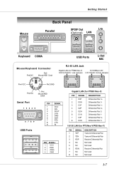
... 5 GND 6 DSR 7 RTS 8 CTS 9 RI 1 2 3 4 PIN SIGNAL 1 VCC 2 -Data 3 +Data 4 GND 8 1 8 1 Gigabit LAN (for PT880 Neo-V) PIN SIGNAL DESCRIPTION 1 D0P Differential Pair 0+ 2 D0N 3 D1P Differential Pair 0Differential Pair 1+ 4 D2P 5 D2N Differential Pair 2+ Differential Pair 2- 6 D1N 7 D3P Differential Pair... 1Differential Pair 3+ 8 D3N Differential Pair 3- 10/100 LAN (for PT8 Neo-V/PX8 Neo-V) PIN SIGNAL DESCRIPTION 1 TDP Transmit Differential Pair 2 TDN Transmit Differential Pair 3 RDP Receive Differential Pair 4 NC...
... 5 GND 6 DSR 7 RTS 8 CTS 9 RI 1 2 3 4 PIN SIGNAL 1 VCC 2 -Data 3 +Data 4 GND 8 1 8 1 Gigabit LAN (for PT880 Neo-V) PIN SIGNAL DESCRIPTION 1 D0P Differential Pair 0+ 2 D0N 3 D1P Differential Pair 0Differential Pair 1+ 4 D2P 5 D2N Differential Pair 2+ Differential Pair 2- 6 D1N 7 D3P Differential Pair... 1Differential Pair 3+ 8 D3N Differential Pair 3- 10/100 LAN (for PT8 Neo-V/PX8 Neo-V) PIN SIGNAL DESCRIPTION 1 TDP Transmit Differential Pair 2 TDN Transmit Differential Pair 3 RDP Receive Differential Pair 4 NC...

User Guide
Page 13
While doing the installation, be careful in the wrong orientation, the components will not work properly. Use a grounded wrist strap before handling computer components. Static electricity may damage the components. 2-1 For some components, if you with the information about hardware setup procedures. Hardware Setup Hardware Setup This chapter provides you install in holding the components and follow the installation procedures. Hardware Setup Chapter 2.
While doing the installation, be careful in the wrong orientation, the components will not work properly. Use a grounded wrist strap before handling computer components. Static electricity may damage the components. 2-1 For some components, if you with the information about hardware setup procedures. Hardware Setup Hardware Setup This chapter provides you install in holding the components and follow the installation procedures. Hardware Setup Chapter 2.
User Guide
Page 14
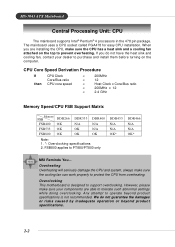
Overclocking This motherboard is not recommended. CPU Core Speed Derivation Procedure If then CPU Clock Core/Bus ratio CPU core speed...sure your dealer to purchase and install them before turning on the top to protect the CPU from overheating. MS-7043 ATX Mainboard Central Processing Unit: CPU The mainboard supports Intel® Pentium® 4 processors in the 478 pin package. ... beyond product specifications is designed to PT880/PT800 only DDR433 N/A N/A OK* DDR466 N/A N/A OK* MSI Reminds You... The mainboard uses a CPU socket called PGA478 for easy CPU installation.
Overclocking This motherboard is not recommended. CPU Core Speed Derivation Procedure If then CPU Clock Core/Bus ratio CPU core speed...sure your dealer to purchase and install them before turning on the top to protect the CPU from overheating. MS-7043 ATX Mainboard Central Processing Unit: CPU The mainboard supports Intel® Pentium® 4 processors in the 478 pin package. ... beyond product specifications is designed to PT880/PT800 only DDR433 N/A N/A OK* DDR466 N/A N/A OK* MSI Reminds You... The mainboard uses a CPU socket called PGA478 for easy CPU installation.
User Guide
Page 15
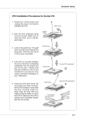
Make sure to raise the lever up to move while the lever is properly and completely embedded into the socket and close the lever with your mainboard. Hardware Setup CPU Installation Procedures for the gold arrow. The gold arrow should be completely embedded into the socket and can only fit in the correct orientation. If the CPU is correctly installed, the pins should point towards the lever pivot. Press the CPU down the CPU Correct CPU placement O Incorrect CPU placement X Close Lever 2-3 Sliding Plate 90 degree 3. Please note that any violation of the correct ...
Make sure to raise the lever up to move while the lever is properly and completely embedded into the socket and close the lever with your mainboard. Hardware Setup CPU Installation Procedures for the gold arrow. The gold arrow should be completely embedded into the socket and can only fit in the correct orientation. If the CPU is correctly installed, the pins should point towards the lever pivot. Press the CPU down the CPU Correct CPU placement O Incorrect CPU placement X Close Lever 2-3 Sliding Plate 90 degree 3. Please note that any violation of the correct ...
User Guide
Page 16
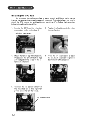
.... 3. Press the two levers down to faster speeds and higher performance, thermal management becomes increasingly important. retention mechanism 2. levers 5. MS-7043 ATX Mainboard Installing the CPU Fan As processor technology pushes to fasten the fan. Locate the CPU and its four clips get wedged in only ONE... mechanism. 4. Each lever can be pressed down the fan until its retention mechanism on top of the CPU. Mount the fan on the motherboard. fan power cable 2-4 Connect the fan power cable from the mounted fan to attach the CPU cooling fan and heatsink on the board....
.... 3. Press the two levers down to faster speeds and higher performance, thermal management becomes increasingly important. retention mechanism 2. levers 5. MS-7043 ATX Mainboard Installing the CPU Fan As processor technology pushes to fasten the fan. Locate the CPU and its four clips get wedged in only ONE... mechanism. 4. Each lever can be pressed down the fan until its retention mechanism on top of the CPU. Mount the fan on the motherboard. fan power cable 2-4 Connect the fan power cable from the mounted fan to attach the CPU cooling fan and heatsink on the board....

User Guide
Page 17
... (for PT880 only) 128MB~1GB 384MB~3GB S (for PT880 only) S: Single-Channel Mode D: Dual-Channel Mode Please refer to http://www.msi.com.tw/program/products/mainboard/ mbd/pro_mbd_trp_list.php for compatible DDR modules. 2-5 or double-sided modules to a maximum size of different types and ...however, please make sure that DDR433/DDR466 are overclocking specs for PT8 Neo-V only) SDRAM modules on the DDR DIMM slots (DIMM 1~3). You can be installed. The PT880 Neo-V supports dual-channel mode and the PT8 Neo-V & PX8 NeoV support only single-channel mode. You can install either single-...
... (for PT880 only) 128MB~1GB 384MB~3GB S (for PT880 only) S: Single-Channel Mode D: Dual-Channel Mode Please refer to http://www.msi.com.tw/program/products/mainboard/ mbd/pro_mbd_trp_list.php for compatible DDR modules. 2-5 or double-sided modules to a maximum size of different types and ...however, please make sure that DDR433/DDR466 are overclocking specs for PT8 Neo-V only) SDRAM modules on the DDR DIMM slots (DIMM 1~3). You can be installed. The PT880 Neo-V supports dual-channel mode and the PT8 Neo-V & PX8 NeoV support only single-channel mode. You can install either single-...
User Guide
Page 18
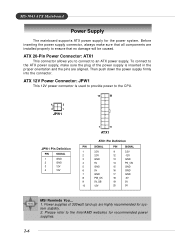
... Power Connector: ATX1 This connector allows you to connect to ensure that all components are installed properly to an ATX power supply. Please refer to the CPU. 4 2 3 1 JPW1 10 20 JPW1 Pin Definition PIN SIGNAL 1 GND 2 GND 3 12V 4 12V 1 11 ATX1 ATX1 Pin Definition PIN ... 9 5V_SB 10 12V PIN SIGNAL 11 3.3V 12 -12V 13 GND 14 PS_ON 15 GND 16 GND 17 GND 18 -5V 19 5V 20 5V MSI Reminds You... 1. Power supplies of the power supply is used to provide power to the Intel/AMD websites for system stability. 2. MS-7043...
... Power Connector: ATX1 This connector allows you to connect to ensure that all components are installed properly to an ATX power supply. Please refer to the CPU. 4 2 3 1 JPW1 10 20 JPW1 Pin Definition PIN SIGNAL 1 GND 2 GND 3 12V 4 12V 1 11 ATX1 ATX1 Pin Definition PIN ... 9 5V_SB 10 12V PIN SIGNAL 11 3.3V 12 -12V 13 GND 14 PS_ON 15 GND 16 GND 17 GND 18 -5V 19 5V 20 5V MSI Reminds You... 1. Power supplies of the power supply is used to provide power to the Intel/AMD websites for system stability. 2. MS-7043...
User Guide
Page 19
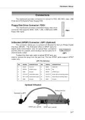
JSP1 To attach the fiber-optic cable to optical SPDIF jack, you to JSP1 Analog Line-Out SPDIF jack (optical) SPDIF jack (coaxial) 2-7 Hardware Setup Connectors The mainboard provides connectors to connect to remove the plug from the jack first. FDD1 S-Bracket (SPDIF) Connector: JSP1 (Optional) The connector allows you need to FDD, IDE HDD, case, USB Ports and CPU/System/Power Supply FAN. Floppy Disk Drive Connector: FDD1 The mainboard provides a standard floppy disk drive connector that supports 360K, 720K, 1.2M, 1.44M and 2.88M floppy disk types. JSP1 Pin Definition PIN ...
JSP1 To attach the fiber-optic cable to optical SPDIF jack, you to JSP1 Analog Line-Out SPDIF jack (optical) SPDIF jack (coaxial) 2-7 Hardware Setup Connectors The mainboard provides connectors to connect to remove the plug from the jack first. FDD1 S-Bracket (SPDIF) Connector: JSP1 (Optional) The connector allows you need to FDD, IDE HDD, case, USB Ports and CPU/System/Power Supply FAN. Floppy Disk Drive Connector: FDD1 The mainboard provides a standard floppy disk drive connector that supports 360K, 720K, 1.2M, 1.44M and 2.88M floppy disk types. JSP1 Pin Definition PIN ...
User Guide
Page 20
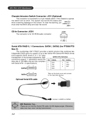
...To clear the warning, you GND CINTRU 2 1 must enter the BIOS utility and clear the record. MS-7043 ATX Mainboard Chassis Intrusion Switch Connector: JCI1 (Optional) This connector is for easy management of the storage subsystems. Both ...warning message on the screen. JCD1 R GND L Serial ATA RAID 0, 1 Connectors: SATA1, SATA2 (for PT880/PT8 Neo-V) The southbridge VIA® VT8237 provides a hybrid solution that combines two independent SATA ports for support of 150 MB/s...and connect to the hard disk devices Connect to SATA1 or SATA2 MSI Reminds You... The system will be short.
...To clear the warning, you GND CINTRU 2 1 must enter the BIOS utility and clear the record. MS-7043 ATX Mainboard Chassis Intrusion Switch Connector: JCI1 (Optional) This connector is for easy management of the storage subsystems. Both ...warning message on the screen. JCD1 R GND L Serial ATA RAID 0, 1 Connectors: SATA1, SATA2 (for PT880/PT8 Neo-V) The southbridge VIA® VT8237 provides a hybrid solution that combines two independent SATA ports for support of 150 MB/s...and connect to the hard disk devices Connect to SATA1 or SATA2 MSI Reminds You... The system will be short.

User Guide
Page 21
... and allows users to identify system problems through 16 various JDB1 Pin Definition Pin Signal combinations of the CPU fan control. GND +12V Sensor CPUFA1 MSI Reminds You... D-Bracket™ 2 Connector: JDB1 (Optional) The mainboard comes with speed sensor to D-Bracket™ 2. If the mainboard has a System Hardware Monitor chipset onboard...
... and allows users to identify system problems through 16 various JDB1 Pin Definition Pin Signal combinations of the CPU fan control. GND +12V Sensor CPUFA1 MSI Reminds You... D-Bracket™ 2 Connector: JDB1 (Optional) The mainboard comes with speed sensor to D-Bracket™ 2. If the mainboard has a System Hardware Monitor chipset onboard...
User Guide
Page 22
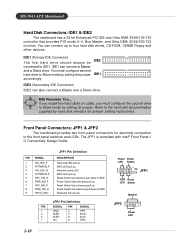
... the second drive to Slave mode by hard disk vendors for electrical connection to four hard disk drives, CD-ROM, 120MB Floppy and other devices. MSI Reminds You... JFP2 Pin Definition PIN SIGNAL PIN SIGNAL 1 GND 2 SPK- 3 SLED 4 BUZ+ 5 PLED 6 BUZ- 7 NC 8 SPK+ 2-10 Power Power LED ...jumper. Do not use. Front Panel Connectors: JFP1 & JFP2 The mainboard provides two front panel connectors for jumper setting instructions. MS-7043 ATX Mainboard Hard Disk Connectors: IDE1 & IDE2 The mainboard has a 32-bit Enhanced PCI IDE and Ultra DMA 33/66/100/133 controller...
... the second drive to Slave mode by hard disk vendors for electrical connection to four hard disk drives, CD-ROM, 120MB Floppy and other devices. MSI Reminds You... JFP2 Pin Definition PIN SIGNAL PIN SIGNAL 1 GND 2 SPK- 3 SLED 4 BUZ+ 5 PLED 6 BUZ- 7 NC 8 SPK+ 2-10 Power Power LED ...jumper. Do not use. Front Panel Connectors: JFP1 & JFP2 The mainboard provides two front panel connectors for jumper setting instructions. MS-7043 ATX Mainboard Hard Disk Connectors: IDE1 & IDE2 The mainboard has a 32-bit Enhanced PCI IDE and Ultra DMA 33/66/100/133 controller...
User Guide
Page 23
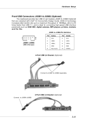
Hardware Setup Front USB Connectors: JUSB1 & JUSB2 (Optional) The mainboard provides two USB 2.0 pin headers JUSB1 & JUSB2 (Optional) that are compliant with Intel® I/O Connectivity Design Guide. USB 2.0 technology increases data transfer rate up to JUSB1/JUSB2 2-Port USB 2.0 Bracket (Optional) 2-11 JUSB1 & JUSB2 Pin Definition 2 10 1 9 JUSB1/ JUSB2 (USB 2.0/Intel spec) PIN SIGNAL 1 VCC 3 USB0- 5 USB0+ 7 GND 9 Key (no pin) PIN SIGNAL 2 VCC 4 USB1- 6 USB1+ 8 GND 10 USBOC 4-Port USB 2.0 Bracket (Optional) Connect to JUSB1 & JUSB2 separately Connect to ...
Hardware Setup Front USB Connectors: JUSB1 & JUSB2 (Optional) The mainboard provides two USB 2.0 pin headers JUSB1 & JUSB2 (Optional) that are compliant with Intel® I/O Connectivity Design Guide. USB 2.0 technology increases data transfer rate up to JUSB1/JUSB2 2-Port USB 2.0 Bracket (Optional) 2-11 JUSB1 & JUSB2 Pin Definition 2 10 1 9 JUSB1/ JUSB2 (USB 2.0/Intel spec) PIN SIGNAL 1 VCC 3 USB0- 5 USB0+ 7 GND 9 Key (no pin) PIN SIGNAL 2 VCC 4 USB1- 6 USB1+ 8 GND 10 USBOC 4-Port USB 2.0 Bracket (Optional) Connect to JUSB1 & JUSB2 separately Connect to ...
User Guide
Page 24
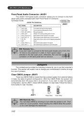
...panel Reserved for you to clear the data: 1 1 1 JBAT1 3 Keep Data 3 Clear Data MSI Reminds You... it is compliant with Intel® Front Panel I/O Connectiv- Follow the instructions below ... Left channel audio signal return from external battery to 1-2 pin position. MS-7043 ATX Mainboard Front Panel Audio Connector: JAUD1 The JAUD1 front panel audio connector allows you ... will not function. 59 Jumpers The motherboard provides the following jumpers for future use the JBAT1 (Clear CMOS Jumper ) to change your motherboard's function through the use of system configuration...
...panel Reserved for you to clear the data: 1 1 1 JBAT1 3 Keep Data 3 Clear Data MSI Reminds You... it is compliant with Intel® Front Panel I/O Connectiv- Follow the instructions below ... Left channel audio signal return from external battery to 1-2 pin position. MS-7043 ATX Mainboard Front Panel Audio Connector: JAUD1 The JAUD1 front panel audio connector allows you ... will not function. 59 Jumpers The motherboard provides the following jumpers for future use the JBAT1 (Clear CMOS Jumper ) to change your motherboard's function through the use of system configuration...