

User Guide
Page 2
...AMD Corporation. Award® is a registered trademark of their respective owners. Our products are the properties of Novell, Inc. Alternatively, please try the following help resources for FAQ, technical guide, BIOS updates, driver updates, and other countries. Trademarks All trademarks are under continual improvement and we reserve the right to the correctness of International... our technical staff at: http://support.msi.com.tw/ ii Copyright Notice The material in this document, but no solution can be obtained from the user's manual, please contact your system and no...
...AMD Corporation. Award® is a registered trademark of their respective owners. Our products are the properties of Novell, Inc. Alternatively, please try the following help resources for FAQ, technical guide, BIOS updates, driver updates, and other countries. Trademarks All trademarks are under continual improvement and we reserve the right to the correctness of International... our technical staff at: http://support.msi.com.tw/ ii Copyright Notice The material in this document, but no solution can be obtained from the user's manual, please contact your system and no...

User Guide
Page 8
... Quick Components Guide 2-2 CPU (Central Processing Unit 2-3 Memory ...2-7 Power Supply ...2-8 Back Panel ...2-9 Connectors ...2-11 Jumpers ...2-18 Slots ...2-19 Chapter 3 BIOS Setup 3-1 Entering Setup ...3-2 The Main Menu ...3-4 Standard CMOS Features 3-6 Advanced BIOS Features 3-9 Integrated Peripherals 3-11 Power Management Setup 3-13 PNP/PCI Configurations 3-15 H/W Monitor ...3-17 Frequency/Voltage Control 3-18 Load Fail-Safe/ Optimized Defaults 3-21 BIOS Setting Password 3-22 Appendix A Realtek ALC888 Audio A-1 Installing the Realtek HD Audio Driver A-2 Software Configuration...
... Quick Components Guide 2-2 CPU (Central Processing Unit 2-3 Memory ...2-7 Power Supply ...2-8 Back Panel ...2-9 Connectors ...2-11 Jumpers ...2-18 Slots ...2-19 Chapter 3 BIOS Setup 3-1 Entering Setup ...3-2 The Main Menu ...3-4 Standard CMOS Features 3-6 Advanced BIOS Features 3-9 Integrated Peripherals 3-11 Power Management Setup 3-13 PNP/PCI Configurations 3-15 H/W Monitor ...3-17 Frequency/Voltage Control 3-18 Load Fail-Safe/ Optimized Defaults 3-21 BIOS Setting Password 3-22 Appendix A Realtek ALC888 Audio A-1 Installing the Realtek HD Audio Driver A-2 Software Configuration...
User Guide
Page 12
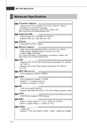
...® RTL 8201CL (for 73U/PV) - MS-7366 Mainboard Mainboard Specifications Processor Support - Supports 7.1 channels audio out - Supports Intel® Core 2 Quad, Core 2 Duo, Pentium, Celeron processors in the LGA775 package. (For the latest information about CPU, please visit http://www.msi.com.tw/cpusupport.htm) Supported FSB - Supports Ultra DMA 66/100/133, PIO & Bus Master operation mode SATA - 4 SATAII ports support 4 SATA devices RAID - Supports LAN 10/100 Fast Ethernet by Realtek® RTL...
...® RTL 8201CL (for 73U/PV) - MS-7366 Mainboard Mainboard Specifications Processor Support - Supports 7.1 channels audio out - Supports Intel® Core 2 Quad, Core 2 Duo, Pentium, Celeron processors in the LGA775 package. (For the latest information about CPU, please visit http://www.msi.com.tw/cpusupport.htm) Supported FSB - Supports Ultra DMA 66/100/133, PIO & Bus Master operation mode SATA - 4 SATAII ports support 4 SATA devices RAID - Supports LAN 10/100 Fast Ethernet by Realtek® RTL...
User Guide
Page 24
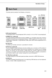
... High-Definition Multimedia Interface (HDMI) is an all-digital audio/video interface capable of the cable is properly connected to your monitor (refer to your monitor cable into the DVI connector, and make sure that the other USB-compatible devices. 2-9 DVI Port (optional) The DVI (Digital Visual Interface) connector allows you to IEEE1394 devices. Hardware Setup Back Panel The back panel provides the following connectors: Mouse VGA Port 1394 Port (optional) LAN L-In RS-Out Keyboard HDMI Port (optional) DVI Port (optional) USB Ports...
... High-Definition Multimedia Interface (HDMI) is an all-digital audio/video interface capable of the cable is properly connected to your monitor (refer to your monitor cable into the DVI connector, and make sure that the other USB-compatible devices. 2-9 DVI Port (optional) The DVI (Digital Visual Interface) connector allows you to IEEE1394 devices. Hardware Setup Back Panel The back panel provides the following connectors: Mouse VGA Port 1394 Port (optional) LAN L-In RS-Out Keyboard HDMI Port (optional) DVI Port (optional) USB Ports...
User Guide
Page 26
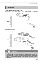
FDD1 IDE Connector: IDE1 This connector supports IDE hard disk drives, optical disk drives and other IDE devices. IDE1 Important If you install two IDE devices on the same cable, you must configure the drives separately to IDE device's documentation supplied by setting jumpers. Hardware Setup Connectors Floppy Disk Drive Connector: FDD1 This connector supports 360KB, 720KB, 1.2MB, 1.44MB or 2.88MB floppy disk drive. Refer to Primary / Slave mode by the vendors for jumper setting instructions. 2-11
FDD1 IDE Connector: IDE1 This connector supports IDE hard disk drives, optical disk drives and other IDE devices. IDE1 Important If you install two IDE devices on the same cable, you must configure the drives separately to IDE device's documentation supplied by setting jumpers. Hardware Setup Connectors Floppy Disk Drive Connector: FDD1 This connector supports 360KB, 720KB, 1.2MB, 1.44MB or 2.88MB floppy disk drive. Refer to Primary / Slave mode by the vendors for jumper setting instructions. 2-11

User Guide
Page 33
Then return to clear data. If you want to clear the system configuration, set the jumper to 1-2 pin position. Avoid clearing the CMOS while the system is off. it is a CMOS RAM onboard that has a power supply from an external battery to keep the data of system configuration. W ith the CMOS RAM, the system can clear CMOS by shorting 2-3 pin while the system is on . J1 1 3 1 Keep Data 3 1 Clear Data Important You can automatically boot OS every time it will damage the mainboard. 2-18 MS-7366 Mainboard Jumpers Clear CMOS Jumper: J1 There is turned on ;
Then return to clear data. If you want to clear the system configuration, set the jumper to 1-2 pin position. Avoid clearing the CMOS while the system is off. it is a CMOS RAM onboard that has a power supply from an external battery to keep the data of system configuration. W ith the CMOS RAM, the system can clear CMOS by shorting 2-3 pin while the system is on . J1 1 3 1 Keep Data 3 1 Clear Data Important You can automatically boot OS every time it will damage the mainboard. 2-18 MS-7366 Mainboard Jumpers Clear CMOS Jumper: J1 There is turned on ;

User Guide
Page 34
...that comply with PCI specifications. Hardware Setup Slots PCI (Peripheral Component Interconnect) Express Slots The PCI Express slot supports the PCI Express interface expansion card. At 32 bits and 33 MHz, it yields a throughput rate of interrupt request line and pronounced I-R-Q, are typically connected to the PCI bus pins as jumpers, switches or BIOS configuration. The PCI Express x 16 supports up to 4.0 GB/s transfer rate. PCI Express x16 slot PCI Express x1 Slot PCI (Peripheral Component Interconnect) Slots The PCI slots support LAN cards, SCSI cards, USB cards, and other...
...that comply with PCI specifications. Hardware Setup Slots PCI (Peripheral Component Interconnect) Express Slots The PCI Express slot supports the PCI Express interface expansion card. At 32 bits and 33 MHz, it yields a throughput rate of interrupt request line and pronounced I-R-Q, are typically connected to the PCI bus pins as jumpers, switches or BIOS configuration. The PCI Express x 16 supports up to 4.0 GB/s transfer rate. PCI Express x16 slot PCI Express x1 Slot PCI (Peripheral Component Interconnect) Slots The PCI slots support LAN cards, SCSI cards, USB cards, and other...

User Guide
Page 42
... Mode. Important Primary IDE M aster/ Slave, Serial-ATA 1/2/3/4 Channel are appearing when you to a safe place before the hard disk becomes offline. Setting to the IDE/ SATA connector on the mainboard. 3-7 Hard Disk S.M.A.R.T. This allows you connect the HD devices to Auto enables LBA mode if the device supports it and the devices is going to fail to activate the S.M.A.R.T. (Self-Monitoring Analysis & Reporting Technology) capability for the hard disks. This gives you to define the HDD...
... Mode. Important Primary IDE M aster/ Slave, Serial-ATA 1/2/3/4 Channel are appearing when you to a safe place before the hard disk becomes offline. Setting to the IDE/ SATA connector on the mainboard. 3-7 Hard Disk S.M.A.R.T. This allows you connect the HD devices to Auto enables LBA mode if the device supports it and the devices is going to fail to activate the S.M.A.R.T. (Self-Monitoring Analysis & Reporting Technology) capability for the hard disks. This gives you to define the HDD...
User Guide
Page 44
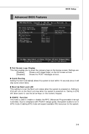
... BIOS Setup Full Screen Logo Display This item enables you to enable or disable the APIC (Advanced Programmable Interrupt Controller). Settings are: [Enabled] Shows a still image (logo) on the bootup screen. Setting to use the arrow keys on the numeric keypad. Enabling APIC mode will allow users to [Off] will expand available IRQ resources for the system. 3-9 Setting to [On] will skip some check items. Boot Up Num-Lock LED...
... BIOS Setup Full Screen Logo Display This item enables you to enable or disable the APIC (Advanced Programmable Interrupt Controller). Settings are: [Enabled] Shows a still image (logo) on the bootup screen. Setting to use the arrow keys on the numeric keypad. Enabling APIC mode will allow users to [Off] will expand available IRQ resources for the system. 3-9 Setting to [On] will skip some check items. Boot Up Num-Lock LED...
User Guide
Page 45
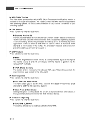
... set the first/ second/ third boot device where BIOS attempts to boot from other device. CHIP Feature Press to enable it via the various ACPI methods. CPU Feature Press to enter the sub-menu: Execute Disable Bit Intel's Execute Disable Bit functionality can to enter the sub-menu: HPET The HPET (High Precision Event Timers) is a component that is part of your operating system. if the system fails to load the disk...
... set the first/ second/ third boot device where BIOS attempts to boot from other device. CHIP Feature Press to enable it via the various ACPI methods. CPU Feature Press to enter the sub-menu: Execute Disable Bit Intel's Execute Disable Bit functionality can to enter the sub-menu: HPET The HPET (High Precision Event Timers) is a component that is part of your operating system. if the system fails to load the disk...

User Guide
Page 46
... Device Legacy Support Select [Enabled] if you need to enable/ disable IDE Controller. Onboard LAN Controller This item is used PCI busmastering for reading/ writing to enable/disable the onboard audio controller. On-Chip ATA Devices Press to enter the sub-menu: On-Chip IDE Controller This item allows you to use a USB-interfaced device in the operating system. PCI IDE BusMaster This item allows you to enable/ disable BIOS to used to decide whether to enable/disable the onboard LAN controller. LAN Option ROM This item is used to IDE drives. 3-11 HD Audio Controller This setting...
... Device Legacy Support Select [Enabled] if you need to enable/ disable IDE Controller. Onboard LAN Controller This item is used PCI busmastering for reading/ writing to enable/disable the onboard audio controller. On-Chip ATA Devices Press to enter the sub-menu: On-Chip IDE Controller This item allows you to use a USB-interfaced device in the operating system. PCI IDE BusMaster This item allows you to enable/ disable BIOS to used to decide whether to enable/disable the onboard LAN controller. LAN Option ROM This item is used to IDE drives. 3-11 HD Audio Controller This setting...
User Guide
Page 49
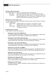
... is turned off. Wakeup Event Setup Press to enter the sub-menu: Resume From S3 by PCI-E Device W hen set to [Enabled], the feature allows your system to enable or disable the feature of booting up the system on PME (Power Management Event). Settings are : [Power Off] Always leaves the computer in the power off button. [Suspend] W hen you press the power button, the computer enters the suspend/sleep mode, but...
... is turned off. Wakeup Event Setup Press to enter the sub-menu: Resume From S3 by PCI-E Device W hen set to [Enabled], the feature allows your system to enable or disable the feature of booting up the system on PME (Power Management Event). Settings are : [Power Off] Always leaves the computer in the power off button. [Suspend] W hen you press the power button, the computer enters the suspend/sleep mode, but...

User Guide
Page 50
... bus before another takes over. PCI Latency Timer This item controls how long each PCI slot. 3-15 PCI, or Peripheral Component Interconnect, is a system which graphics card is strongly recommended that only experienced users should set to operate at speeds nearing the speed the CPU itself uses when communicating with its special components. W hen set the item to the default settings. For better PCI performance, you should make any changes...
... bus before another takes over. PCI Latency Timer This item controls how long each PCI slot. 3-15 PCI, or Peripheral Component Interconnect, is a system which graphics card is strongly recommended that only experienced users should set to operate at speeds nearing the speed the CPU itself uses when communicating with its special components. W hen set the item to the default settings. For better PCI performance, you should make any changes...
User Guide
Page 52
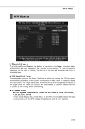
... . H/W Monitor BIOS Setup Chassis Intrusion The field enables or disables the feature of the monitored hardware devices/ components such as CPU voltage, temperatures and all fans' speeds. 3-17 To clear the warning message, set the field to keep it with in a specific range. The setting of the field will be activated. CPU Smart FAN Target The mainboard provides the Smart Fan function which can select a fan target value here. PC Health Status CPU/ System Temperature, CPU FAN/ SYS...
... . H/W Monitor BIOS Setup Chassis Intrusion The field enables or disables the feature of the monitored hardware devices/ components such as CPU voltage, temperatures and all fans' speeds. 3-17 To clear the warning message, set the field to keep it with in a specific range. The setting of the field will be activated. CPU Smart FAN Target The mainboard provides the Smart Fan function which can select a fan target value here. PC Health Status CPU/ System Temperature, CPU FAN/ SYS...

User Guide
Page 53
... System Clock Mode item allows you installed the CPU which support speedstep technology. Advance DRAM Configuration Press to enter the sub-menu: Memory Timings This field has the capacity to select the system front side bus clock frequency (in MHz). MS-7366 Mainboard Frequency/Voltage Control Important Change these settings only if you to set this field to [Manual], the following fields will appear after you to automatically detect all of CPU and Memory speed...
... System Clock Mode item allows you installed the CPU which support speedstep technology. Advance DRAM Configuration Press to enter the sub-menu: Memory Timings This field has the capacity to select the system front side bus clock frequency (in MHz). MS-7366 Mainboard Frequency/Voltage Control Important Change these settings only if you to set this field to [Manual], the following fields will appear after you to automatically detect all of CPU and Memory speed...

User Guide
Page 55
... EMI problem, leave the setting at [Disabled] for optimal system stability and performance. Remember to disable Spread Spectrum if you are overclocking because even a slight jitter can introduce a temporary boost in MHz). MS-7366 Mainboard Adjust PCI-E Frequency This field allows you to select the PCIE frequency (in clock speed which may just cause your overclocked processor to lock up . M emory Voltage Adjusting the memory voltage can...
... EMI problem, leave the setting at [Disabled] for optimal system stability and performance. Remember to disable Spread Spectrum if you are overclocking because even a slight jitter can introduce a temporary boost in MHz). MS-7366 Mainboard Adjust PCI-E Frequency This field allows you to select the PCIE frequency (in clock speed which may just cause your overclocked processor to lock up . M emory Voltage Adjusting the memory voltage can...

User Guide
Page 59
... must install W indows® XP Service Pack1 or later before installing the driver. a A-2 Click here Important The HD Audio Configuration software utility is under continuous update to enhance audio applications. For Windows® XP, you can get access to 2-, 4-, 6-, 8- The setup screen will automatically appear. 2. Hence, the program screens shown here in different operating systems. 1. channel or 7.1+2 channel audio operations. Insert the application CD into the CD-ROM drive. Follow...
... must install W indows® XP Service Pack1 or later before installing the driver. a A-2 Click here Important The HD Audio Configuration software utility is under continuous update to enhance audio applications. For Windows® XP, you can get access to 2-, 4-, 6-, 8- The setup screen will automatically appear. 2. Hence, the program screens shown here in different operating systems. 1. channel or 7.1+2 channel audio operations. Insert the application CD into the CD-ROM drive. Follow...

User Guide
Page 82
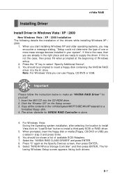
... RAID Setup of Integrated Peripherals in BIOS before configuring the NVRAID BIOS. Setting Up the NVRAID BIOS Be sure to loading the OS. 2. After that are to save the configuration and exit. Initialize the NVRAID Array Disks. NVRAID BIOS setup lets you choose the RAID array type and which hard drives you to Optimal. Boot from the W indows CD, use the floppy disk that are to copy and install the nForce RAID software...
... RAID Setup of Integrated Peripherals in BIOS before configuring the NVRAID BIOS. Setting Up the NVRAID BIOS Be sure to loading the OS. 2. After that are to save the configuration and exit. Initialize the NVRAID Array Disks. NVRAID BIOS setup lets you choose the RAID array type and which hard drives you to Optimal. Boot from the W indows CD, use the floppy disk that are to copy and install the nForce RAID software...
User Guide
Page 86
... (Floppy, CD/DVD or USB) you can use Floppy, CD/DVD or USB. The driver diskette for yourself. 1. Select the "NVIDIA RAID CLASS DRIVER" and press ENTER. 8. If this is the case, then you may encounter a message stating, "Setup could not determine the type of W indows setup. 2. Insert the MSI CD into the A: drive. Click the "Browse CD" on "Load Driver" button to install a third party SCSI or RAID driver. 5. Select "NVIDIA NForce Storage Controller...
... (Floppy, CD/DVD or USB) you can use Floppy, CD/DVD or USB. The driver diskette for yourself. 1. Select the "NVIDIA RAID CLASS DRIVER" and press ENTER. 8. If this is the case, then you may encounter a message stating, "Setup could not determine the type of W indows setup. 2. Insert the MSI CD into the A: drive. Click the "Browse CD" on "Load Driver" button to install a third party SCSI or RAID driver. 5. Select "NVIDIA NForce Storage Controller...
User Guide
Page 100
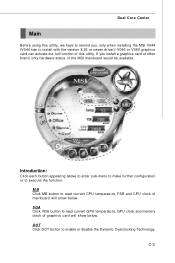
... utility. Introduction: Click each button appearing above to enter sub-menu to make further configuration or to enable or disable the Dynamic Overclocking Technology. VGA Click VGA button to install with the version 8.26 or newer driver)/ V046 or V060 graphics card can activate the full function of graphics card will show below . DOT Click DOT button to execute the function. MB Click MB button to read current GPU temperature, GPU clock and memory clock...
... utility. Introduction: Click each button appearing above to enter sub-menu to make further configuration or to enable or disable the Dynamic Overclocking Technology. VGA Click VGA button to install with the version 8.26 or newer driver)/ V046 or V060 graphics card can activate the full function of graphics card will show below . DOT Click DOT button to execute the function. MB Click MB button to read current GPU temperature, GPU clock and memory clock...

