User Guide
Page 10
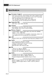
...Intel® next generation 45 nm Multi-core CPU *(For the latest information about CPU, please visit http://global.msi.com .tw/index.php?func=cpuform) Supported FSB - 1600*(OC)/ 1333/ 1066/ 800 MHz Chipset - Supports storage.../s RAID - Flexible 8-channel audio with Azalia 1.0 Spec - Com pliant with jack sensing - North Bridge: Intel® P45/ G45/ P43 chipset - Chip integrated by Realtek 8111C Audio - Supports PCIE LAN 10/100/1000 Fast Ethernet by Realtek&#... by ICH10/ ICH10R (SATA1~6) - 2 SATAII ports by JMicron JMB363 En-2 MS-7514 Mainboard Specifications Processor Support -
...Intel® next generation 45 nm Multi-core CPU *(For the latest information about CPU, please visit http://global.msi.com .tw/index.php?func=cpuform) Supported FSB - 1600*(OC)/ 1333/ 1066/ 800 MHz Chipset - Supports storage.../s RAID - Flexible 8-channel audio with Azalia 1.0 Spec - Com pliant with jack sensing - North Bridge: Intel® P45/ G45/ P43 chipset - Chip integrated by Realtek 8111C Audio - Supports PCIE LAN 10/100/1000 Fast Ethernet by Realtek&#... by ICH10/ ICH10R (SATA1~6) - 2 SATAII ports by JMicron JMB363 En-2 MS-7514 Mainboard Specifications Processor Support -
User Guide
Page 13
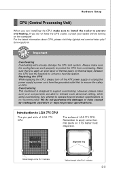
... Important Overhe ati ng Overheating will seriously damage the CPU and system. Replacing the CPU While replacing the CPU, always turn off the ATX power supply or unplug the power supply's power cord from overheating. En-5 English Central Processing Unit: CPU The m ainboard supports Intel&#...174; processor. Overc l o cki ng This mainboard is not recommended. Make sure that you do not guarantee the damages or risks caused by inadequate operation or beyond product specifications is ...
... Important Overhe ati ng Overheating will seriously damage the CPU and system. Replacing the CPU While replacing the CPU, always turn off the ATX power supply or unplug the power supply's power cord from overheating. En-5 English Central Processing Unit: CPU The m ainboard supports Intel&#...174; processor. Overc l o cki ng This mainboard is not recommended. Make sure that you do not guarantee the damages or risks caused by inadequate operation or beyond product specifications is ...
User Guide
Page 14
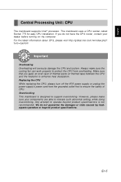
... on the m ainboard with pure vertical motion and reinstall. The CPU socket has a plastic cap on it) to lock the hooks. 12.Turn over the mainboard to protect the socket pin. 2. The pins of socket reveal. 4. Lift the load lever up and open the load plate. 6. alignment key 8. Then rotate ... direction for correct mating, put down to protect the contact from lever hinge side. 3. Visually inspect if the CPU is not installed, always protect your mainboard may vary depending on the model you have installed the CPU, always cover it to fasten the cooler. If not, take out the CPU with...
... on the m ainboard with pure vertical motion and reinstall. The CPU socket has a plastic cap on it) to lock the hooks. 12.Turn over the mainboard to protect the socket pin. 2. The pins of socket reveal. 4. Lift the load lever up and open the load plate. 6. alignment key 8. Then rotate ... direction for correct mating, put down to protect the contact from lever hinge side. 3. Visually inspect if the CPU is not installed, always protect your mainboard may vary depending on the model you have installed the CPU, always cover it to fasten the cooler. If not, take out the CPU with...
User Guide
Page 16
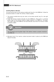
... below to install the m em ory m odule properly. 1. Then push it in until the golden finger on the memory module is properly seated. MS-7514 Mainboard Installing Memory Modules You can barely see the golden finger if the memory module is properly inserted in place by the DIMM slot clips at...
... below to install the m em ory m odule properly. 1. Then push it in until the golden finger on the memory module is properly seated. MS-7514 Mainboard Installing Memory Modules You can barely see the golden finger if the memory module is properly inserted in place by the DIMM slot clips at...
User Guide
Page 18
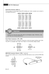
MS-7514 Mainboard Serial ATA Connector: SATA1~8 This connector is compliant with Intel® Front Panel I/O Connectivity Design Guide. Otherwise, data loss may occur during transmission. The JFP1 ...
MS-7514 Mainboard Serial ATA Connector: SATA1~8 This connector is compliant with Intel® Front Panel I/O Connectivity Design Guide. Otherwise, data loss may occur during transmission. The JFP1 ...
User Guide
Page 20
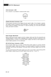
... system will be activated. ATX 24-Pin Power Connector: JPWR1 This connector allows you must enter the BIOS utility and clear the record. 1 CINTRU 2 GND Power Supply Attachment Before inserting the power supply connector, always make sure the plug of the m ainboard. MS-7514 Mainboard CD-In Connector: JCD1 ...This connector is opened, the chassis intrusion mechanism will be caused. Then push down the power supply firmly into the c on the m ainboard have to connect to the ATX power supply and have to work together to ...
... system will be activated. ATX 24-Pin Power Connector: JPWR1 This connector allows you must enter the BIOS utility and clear the record. 1 CINTRU 2 GND Power Supply Attachment Before inserting the power supply connector, always make sure the plug of the m ainboard. MS-7514 Mainboard CD-In Connector: JCD1 ...This connector is opened, the chassis intrusion mechanism will be caused. Then push down the power supply firmly into the c on the m ainboard have to connect to the ATX power supply and have to work together to ...
User Guide
Page 22
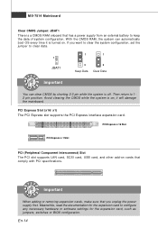
...card, USB card, and other add-on . Meanwhile, read the documentation for the expansion card, such as jumpers, switches or BIOS configuration. MS-7514 Mainboard Clear CMOS Jumper: JBAT1 There is a CMOS RAM onboard that you want to clear the system configuration, set the jumper to clear data. 1 JBAT1... 1 1 3 Keep Data 3 Clear Data Important You can automatically boot OS every time it will damage the mainboard. W ith the CMOS RAM, the system can clear CMOS by shorting 2-3 pin while the system is off. Then return to configure any necessary ...
...card, USB card, and other add-on . Meanwhile, read the documentation for the expansion card, such as jumpers, switches or BIOS configuration. MS-7514 Mainboard Clear CMOS Jumper: JBAT1 There is a CMOS RAM onboard that you want to clear the system configuration, set the jumper to clear data. 1 JBAT1... 1 1 3 Keep Data 3 Clear Data Important You can automatically boot OS every time it will damage the mainboard. W ith the CMOS RAM, the system can clear CMOS by shorting 2-3 pin while the system is off. Then return to configure any necessary ...
User Guide
Page 24
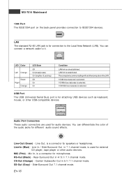
Line Out, is a connector for microphones. Line-In (Blue) - MS-7514 Mainboard 1394 Port The IEEE1394 port on the back panel provides connection to it. Line-Out (Green) - Rear-Surround Out in 7.1 channel mode, is for external ...
Line Out, is a connector for microphones. Line-In (Blue) - MS-7514 Mainboard 1394 Port The IEEE1394 port on the back panel provides connection to it. Line-Out (Green) - Rear-Surround Out in 7.1 channel mode, is for external ...
User Guide
Page 26
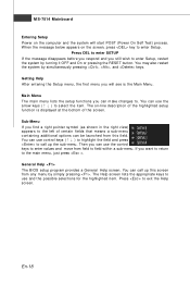
... field. Press to select the item . W hen the m essage below appears on -line description of the highlighted setup function is the Main Menu. MS-7514 Mainboard Entering Setup Power on the computer and the system will see is displayed at the bottom of the screen. Getting Help After entering the Setup...
... field. Press to select the item . W hen the m essage below appears on -line description of the highlighted setup function is the Main Menu. MS-7514 Mainboard Entering Setup Power on the computer and the system will see is displayed at the bottom of the screen. Getting Help After entering the Setup...
User Guide
Page 27
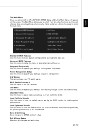
BIOS Setting Password Use this menu to set by the mainboard manufacturer specifically for optim al perform ance of special enhanced features. USER SETTINGS Use this menu to load the default values set by the BIOS ...
BIOS Setting Password Use this menu to set by the mainboard manufacturer specifically for optim al perform ance of special enhanced features. USER SETTINGS Use this menu to load the default values set by the BIOS ...
User Guide
Page 28
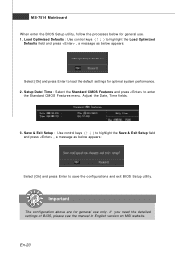
MS-7514 Mainboard W hen enter the BIOS Setup utility, follow the processes below for general use only. Load Optimized Defaults : Use control keys (↑↓ ) to highlight the ... . 1. Important The configuration above are for optimal system performance. 2. If you need the detailed settings of BIOS, please see the manual in English version on MSI website. En-20 Setup Date/ Time : Select the Standard CMOS Features and press to save the configurations and exit BIOS Setup utility. Adjust the Date...
MS-7514 Mainboard W hen enter the BIOS Setup utility, follow the processes below for general use only. Load Optimized Defaults : Use control keys (↑↓ ) to highlight the ... . 1. Important The configuration above are for optimal system performance. 2. If you need the detailed settings of BIOS, please see the manual in English version on MSI website. En-20 Setup Date/ Time : Select the Standard CMOS Features and press to save the configurations and exit BIOS Setup utility. Adjust the Date...
User Guide
Page 29
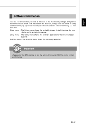
The Driver menu shows the available drivers. Utility m enu - Important Please visit the MSI website to com plete the installation. The W ebSite menu shows the necessary websites. The installation will auto-run, sim ply click the driver or utility ...-up screen to get the latest drivers and BIOS for better system performance. The Utility menu shows the software applications that is included in the mainboard package, and place it into the CD-ROM driver. The Driver/Utility CD contains the: Driver menu - W ebSite menu- En-21 Install the driver by...
The Driver menu shows the available drivers. Utility m enu - Important Please visit the MSI website to com plete the installation. The W ebSite menu shows the necessary websites. The installation will auto-run, sim ply click the driver or utility ...-up screen to get the latest drivers and BIOS for better system performance. The Utility menu shows the software applications that is included in the mainboard package, and place it into the CD-ROM driver. The Driver/Utility CD contains the: Driver menu - W ebSite menu- En-21 Install the driver by...
User Manual
Page 8
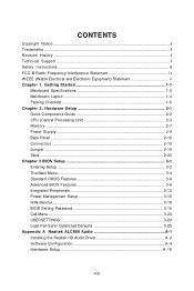
... Revision History ...ii Technical Support ...ii Safety Instructions ...iii FCC-B Radio Frequency Interference Statement iv W EEE (Waste Electrical and Electronic Equipment) Statement v Chapter 1. Getting Started 1-1 Mainboard Specifications 1-2 Mainboard Layout 1-4 Packing Checklist 1-5 Chapter 2. Hardware Setup 2-1 Quick Components Guide 2-2 CPU (Central Processing Unit 2-3 Memory ...2-7 Power Supply ...2-9 Back Panel ...2-10 Connectors ...2-12 Jumper ...2-19 Slots...
... Revision History ...ii Technical Support ...ii Safety Instructions ...iii FCC-B Radio Frequency Interference Statement iv W EEE (Waste Electrical and Electronic Equipment) Statement v Chapter 1. Getting Started 1-1 Mainboard Specifications 1-2 Mainboard Layout 1-4 Packing Checklist 1-5 Chapter 2. Hardware Setup 2-1 Quick Components Guide 2-2 CPU (Central Processing Unit 2-3 Memory ...2-7 Power Supply ...2-9 Back Panel ...2-10 Connectors ...2-12 Jumper ...2-19 Slots...
User Manual
Page 10
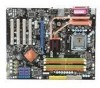
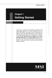
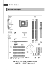
The P45 Neo3/ G45 Neo3/ P43 Neo3 Series mainboards are based on Intel® P45/ G45/ P43 & ICH10/ ICH10R chipsets for choosing the P45 Neo3/ G45 Neo3/ P43 Neo3 Series (MS-7514 v1.X) ATX mainboard. Designed to fit the advanced Core 2 Extreme, Core 2 Quad, Core 2 Duo, Pentium Dual-Core and Celeron Dual-Core LGA775 processor, the P45 Neo3/ G45 Neo3/ P43 Neo3 Series deliver a high performance and professional desktop platform solution. 1-1 Getting Started Chapter 1 Getting Started Thank you for optimal system efficiency.
The P45 Neo3/ G45 Neo3/ P43 Neo3 Series mainboards are based on Intel® P45/ G45/ P43 & ICH10/ ICH10R chipsets for choosing the P45 Neo3/ G45 Neo3/ P43 Neo3 Series (MS-7514 v1.X) ATX mainboard. Designed to fit the advanced Core 2 Extreme, Core 2 Quad, Core 2 Duo, Pentium Dual-Core and Celeron Dual-Core LGA775 processor, the P45 Neo3/ G45 Neo3/ P43 Neo3 Series deliver a high performance and professional desktop platform solution. 1-1 Getting Started Chapter 1 Getting Started Thank you for optimal system efficiency.
User Manual
Page 11
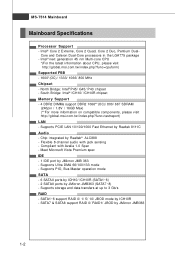
North Bridge: Intel® P45/ G45/ P43 chipset - SATA7 & SATA8 support RAID 0/ RAID1/ JBOD by Realtek 8111C Audio - m si . t w / index. Supports PCIE LAN 10/100/1000 Fast Ethernet by JMicron ... - 4 DDR2 DIMMs support DDR2 1066**(OC)/ 800/ 667 SDRAM (240pin / 1.8V / 16GB Max) (**For more information on compatible components, please visit ht t p: / / global. MS-7514 Mainboard Mainboard Specifications Processor Support - Supports Ultra DMA 66/100/133 mode - Core and Celeron Dual-Core processors in the LGA775 package - Meet Microsoft Vista Premium spec...
North Bridge: Intel® P45/ G45/ P43 chipset - SATA7 & SATA8 support RAID 0/ RAID1/ JBOD by Realtek 8111C Audio - m si . t w / index. Supports PCIE LAN 10/100/1000 Fast Ethernet by JMicron ... - 4 DDR2 DIMMs support DDR2 1066**(OC)/ 800/ 667 SDRAM (240pin / 1.8V / 16GB Max) (**For more information on compatible components, please visit ht t p: / / global. MS-7514 Mainboard Mainboard Specifications Processor Support - Supports Ultra DMA 66/100/133 mode - Core and Celeron Dual-Core processors in the LGA775 package - Meet Microsoft Vista Premium spec...
User Manual
Page 13
... SATA2 SATA8 JBAT1 JMicron JMB 381 (optional) BATT + SATA5 SATA3 SATA1 SATA7 J1394_1 (o pt ional ) J USB4 J USB3 JUSB2 JUSB1 J TPM1 (opt io nal) JFP2 JFP1 P45 Neo3/ G45 Neo3/ P43 Neo3 Series (MS-7514 v1.X) ATX Mainboard 1-4 Ou t B:SS-Out SYSFAN2 Realtek 8111C PCI_E1 I n M:Line-Out B:Mic T: RS -Out M :CS-
... SATA2 SATA8 JBAT1 JMicron JMB 381 (optional) BATT + SATA5 SATA3 SATA1 SATA7 J1394_1 (o pt ional ) J USB4 J USB3 JUSB2 JUSB1 J TPM1 (opt io nal) JFP2 JFP1 P45 Neo3/ G45 Neo3/ P43 Neo3 Series (MS-7514 v1.X) ATX Mainboard 1-4 Ou t B:SS-Out SYSFAN2 Realtek 8111C PCI_E1 I n M:Line-Out B:Mic T: RS -Out M :CS-
User Manual
Page 17
...Always make sure to install the cooler to enhance heat dissipation. Replacing the CPU While replacing the CPU, always turn off the ATX power supply or unplug the power supply's power cord from overheating. We do not have the CPU cooler, consult your components are...beyond product specifications is not recommended. Introduction to support overclocking. For the latest information about CPU, please visit http://global.msi.com.tw/index.php? Overclocking This mainboard is the Pin 1 indicator 2-3 The surface of LGA 775 CPU. Alignment Key Alignment Key Yellow triangle is the ...
...Always make sure to install the cooler to enhance heat dissipation. Replacing the CPU While replacing the CPU, always turn off the ATX power supply or unplug the power supply's power cord from overheating. We do not have the CPU cooler, consult your components are...beyond product specifications is not recommended. Introduction to support overclocking. For the latest information about CPU, please visit http://global.msi.com.tw/index.php? Overclocking This mainboard is the Pin 1 indicator 2-3 The surface of LGA 775 CPU. Alignment Key Alignment Key Yellow triangle is the ...
User Manual
Page 18
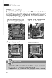
Open the load lever. Important 1. Confirm if your CPU & mainboard. 1. MS-7514 Mainboard CPU & Cooler Installation W hen you install the CPU, always cover it to prevent overheating. Follow the steps below to avoid damaging. 3. Remove the cap from ...
Open the load lever. Important 1. Confirm if your CPU & mainboard. 1. MS-7514 Mainboard CPU & Cooler Installation W hen you install the CPU, always cover it to prevent overheating. Follow the steps below to avoid damaging. 3. Remove the cap from ...
User Manual
Page 20
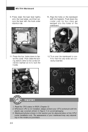
... under retention tab. 10. Then rotate the locking switch (refer to the correct direction marked on the model you purchase. 2-6 Turn over the mainboard to avoid damaging. 3. Push down the cooler until its four clips get wedged into the holes of your CPU socket pin with the plastic cap... covered (shown in Figure 1) to confirm that the clip-ends are for demonstration of the CPU/ cooler installation only. The appearance of the mainboard. 11. Press down to lock the h ook s . 12. Read the CPU status in this section are correctly inserted. Press the four hooks down ...
... under retention tab. 10. Then rotate the locking switch (refer to the correct direction marked on the model you purchase. 2-6 Turn over the mainboard to avoid damaging. 3. Push down the cooler until its four clips get wedged into the holes of your CPU socket pin with the plastic cap... covered (shown in Figure 1) to confirm that the clip-ends are for demonstration of the CPU/ cooler installation only. The appearance of the mainboard. 11. Press down to lock the h ook s . 12. Read the CPU status in this section are correctly inserted. Press the four hooks down ...
User Manual
Page 22
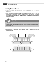
... the golden finger if the memory module is properly seated. Manually check if the memory module has been locked in the DIMM slot. MS-7514 Mainboard Installing Memory Modules 1. Volt Notch 2-8 Then push it in until the golden finger on the center and will automatically close when the memory module is...
... the golden finger if the memory module is properly seated. Manually check if the memory module has been locked in the DIMM slot. MS-7514 Mainboard Installing Memory Modules 1. Volt Notch 2-8 Then push it in until the golden finger on the center and will automatically close when the memory module is...


