User Guide
Page 11
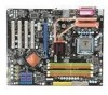
... - 1 1394 pinheader (optional) - 1 chassis intrusion connector - 1 SPDIF-out pinheader - 1 CD-in connector - 1 front audio pinheader - 1 TPM Module connector (optional) - 2 Hardware Overclock FSB jumpers (JB1 & JB2) TPM (optional) - English 1394 (optional) - ATX (30.5cm X 24.5cm) Mounting - 9 mounting holes En-3 Supports TPM Slots - 1 PCI Express x16 slot, support up to PCI Express 2.0 x16...
... - 1 1394 pinheader (optional) - 1 chassis intrusion connector - 1 SPDIF-out pinheader - 1 CD-in connector - 1 front audio pinheader - 1 TPM Module connector (optional) - 2 Hardware Overclock FSB jumpers (JB1 & JB2) TPM (optional) - English 1394 (optional) - ATX (30.5cm X 24.5cm) Mounting - 9 mounting holes En-3 Supports TPM Slots - 1 PCI Express x16 slot, support up to PCI Express 2.0 x16...
User Guide
Page 13
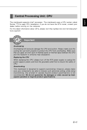
... not guarantee the damages or risks caused by inadequate operation or beyond product specifications is designed to tolerate such abnormal setting, while doing overclocking. The mainboard uses a CPU socket called Socket 775 for easy CPU installation. Any attempt to enhance heat dissipation. Replacing the CPU ...While replacing the CPU, always turn off the ATX power supply or unplug the power supply's power cord from overheating. Overc l o cki ng This mainboard is not recommended. En-5 If...
... not guarantee the damages or risks caused by inadequate operation or beyond product specifications is designed to tolerate such abnormal setting, while doing overclocking. The mainboard uses a CPU socket called Socket 775 for easy CPU installation. Any attempt to enhance heat dissipation. Replacing the CPU ...While replacing the CPU, always turn off the ATX power supply or unplug the power supply's power cord from overheating. Overc l o cki ng This mainboard is not recommended. En-5 If...

User Guide
Page 21
Make sure that you power off the system before changing the jumpers. 2. English ATX 12V Power Connector (2x2-Pin): JPWR2 This 12V power connector is used to provide power to the CPU. 21 GND GND 12V 12V 43 TPM ...: JTPM1 (optional) This connector connects to the TPM security platform manual for more details and usages. Please refer to a TPM (Trusted Platform Module) module (optional). Overclocking may cause instability or crash during boot, then please restore the jumpers to set the FSB. 1 3 JB1 JB2 Default 1 JB1 1 JB2 1 3 1 3 1 3 1 3 200->266 MHz 200...
Make sure that you power off the system before changing the jumpers. 2. English ATX 12V Power Connector (2x2-Pin): JPWR2 This 12V power connector is used to provide power to the CPU. 21 GND GND 12V 12V 43 TPM ...: JTPM1 (optional) This connector connects to the TPM security platform manual for more details and usages. Please refer to a TPM (Trusted Platform Module) module (optional). Overclocking may cause instability or crash during boot, then please restore the jumpers to set the FSB. 1 3 JB1 JB2 Default 1 JB1 1 JB2 1 3 1 3 1 3 1 3 200->266 MHz 200...
User Guide
Page 27
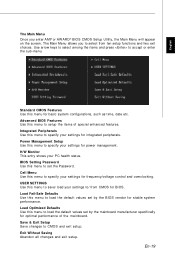
Power Management Setup Use this menu to specify your settings for frequency/voltage control and overclocking. Cell Menu Use this menu to specify your settings to/ from ten setup functions and two exit choices. Integrated Peripherals Use this menu to save/ ...
Power Management Setup Use this menu to specify your settings for frequency/voltage control and overclocking. Cell Menu Use this menu to specify your settings to/ from ten setup functions and two exit choices. Integrated Peripherals Use this menu to save/ ...
User Manual
Page 9
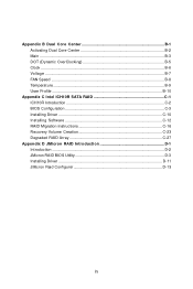
Appendix B Dual Core Center B-1 Activating Dual Core Center B-2 Main ...B-3 DOT (Dynamic OverClocking B-5 Clock ...B-6 Voltage ...B-7 FAN Speed ...B-8 Temperature ...B-9 User Profile ...B-10 Appendix C Intel ICH10R SATA RAID C-1 ICH10R Introduction C-2 BIOS Configuration C-3 Installing Driver C-10 Installing Software C-12 RAID Migration Instructions C-16 Recovery Volume Creation C-23 Degraded RAID Array C-27 Appendix D JM icron RAID Introduction D-1 Introduction ...D-2 JMicron RAID BIOS Utility D-3 Installing Driver D-11 JMicron Raid Configurer D-13 ix
Appendix B Dual Core Center B-1 Activating Dual Core Center B-2 Main ...B-3 DOT (Dynamic OverClocking B-5 Clock ...B-6 Voltage ...B-7 FAN Speed ...B-8 Temperature ...B-9 User Profile ...B-10 Appendix C Intel ICH10R SATA RAID C-1 ICH10R Introduction C-2 BIOS Configuration C-3 Installing Driver C-10 Installing Software C-12 RAID Migration Instructions C-16 Recovery Volume Creation C-23 Degraded RAID Array C-27 Appendix D JM icron RAID Introduction D-1 Introduction ...D-2 JMicron RAID BIOS Utility D-3 Installing Driver D-11 JMicron Raid Configurer D-13 ix

User Manual
Page 12
ATX (30.5cm X 24.5cm) Mounting - 9 mounting holes 1-3 Getting Started 1394 (optional) - Supports 1394 by JMicron JMB381 FDD - 1 floppy port - Supports 1 FDD with 360KB, 720KB, 1.2MB, 1....-Board Pinheaders / Connectors - 4 USB 2.0 pinheaders - 1 1394 pinheader (optional) - 1 chassis intrusion connector - 1 SPDIF-out pinheader - 1 CD-in connector - 1 front audio pinheader - 1 TPM Module connector (optional) - 2 Hardware Overclock FSB jumpers (JB1 & JB2) TPM (optional) - Supports TPM Slots - 1 PCI Express x16 slot, support up to PCI Express 2.0 x16 speed - 1 PCI Express x1 slot - 4 PCI...
ATX (30.5cm X 24.5cm) Mounting - 9 mounting holes 1-3 Getting Started 1394 (optional) - Supports 1394 by JMicron JMB381 FDD - 1 floppy port - Supports 1 FDD with 360KB, 720KB, 1.2MB, 1....-Board Pinheaders / Connectors - 4 USB 2.0 pinheaders - 1 1394 pinheader (optional) - 1 chassis intrusion connector - 1 SPDIF-out pinheader - 1 CD-in connector - 1 front audio pinheader - 1 TPM Module connector (optional) - 2 Hardware Overclock FSB jumpers (JB1 & JB2) TPM (optional) - Supports TPM Slots - 1 PCI Express x16 slot, support up to PCI Express 2.0 x16 speed - 1 PCI Express x1 slot - 4 PCI...
User Manual
Page 17
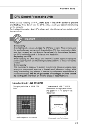
...CPU. The surface of LGA 775 CPU. For the latest information about CPU, please visit http://global.msi.com.tw/index.php? Overclocking This mainboard is designed to support overclocking. Introduction to LGA 775 CPU The pin-pad side of LGA 775 CPU. Always make sure to ...turn off the ATX power supply or unplug the power supply's power cord from overheating. func=cpuform Important Overheating Overheating will seriously damage the CPU and system. Hardware Setup CPU (Central Processing Unit) W hen you are able to tolerate such abnormal setting, while doing overclocking. We do...
...CPU. The surface of LGA 775 CPU. For the latest information about CPU, please visit http://global.msi.com.tw/index.php? Overclocking This mainboard is designed to support overclocking. Introduction to LGA 775 CPU The pin-pad side of LGA 775 CPU. Always make sure to ...turn off the ATX power supply or unplug the power supply's power cord from overheating. func=cpuform Important Overheating Overheating will seriously damage the CPU and system. Hardware Setup CPU (Central Processing Unit) W hen you are able to tolerate such abnormal setting, while doing overclocking. We do...

User Manual
Page 33
... time it will damage the mainboard. Avoid clearing the CMOS while the system is on . it is turned on ; Hardware Overclock FSB Jumpers: JB1, JB2 You can overclock the FSB to increase the processor frequency by shorting 2-3 pin while the system is off the system before changing the jumpers.... 2. Overclocking may cause instability or crash during boot, then please restore the jumpers to 1-2 pin position. Hardware Setup Jumpers Clear CMOS Jumper: JBAT1 There ...
... time it will damage the mainboard. Avoid clearing the CMOS while the system is on . it is turned on ; Hardware Overclock FSB Jumpers: JB1, JB2 You can overclock the FSB to increase the processor frequency by shorting 2-3 pin while the system is off the system before changing the jumpers.... 2. Overclocking may cause instability or crash during boot, then please restore the jumpers to 1-2 pin position. Hardware Setup Jumpers Clear CMOS Jumper: JBAT1 There ...

User Manual
Page 39
... system configurations, such as time, date etc. Cell Menu Use this menu to specify your settings to specify your settings for frequency/voltage control and overclocking. USER SETTINGS Use this menu to specify your PC health status. H/W Monitor This entry shows your settings for BIOS. MS-7514 Mainboard The Main Menu...
... system configurations, such as time, date etc. Cell Menu Use this menu to specify your settings to specify your settings for frequency/voltage control and overclocking. USER SETTINGS Use this menu to specify your PC health status. H/W Monitor This entry shows your settings for BIOS. MS-7514 Mainboard The Main Menu...

User Manual
Page 55
... need to enhance the overall performance. 3-20 Usually the Dynamic Overclocking Technology will be boosted up automatically to adjust the best frequency automatically. W hen the system is an automatic overclocking function, included in the low load balance, it will restore the... default settings instead. Control D.O.T. (Dynamic Overclocking Technology) is temporarily suspending or staying in the MSITM's newly developed Dual...
... need to enhance the overall performance. 3-20 Usually the Dynamic Overclocking Technology will be boosted up automatically to adjust the best frequency automatically. W hen the system is an automatic overclocking function, included in the low load balance, it will restore the... default settings instead. Control D.O.T. (Dynamic Overclocking Technology) is temporarily suspending or staying in the MSITM's newly developed Dual...
User Manual
Page 56
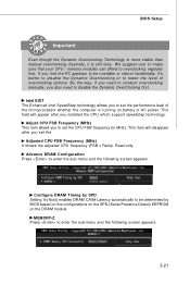
...set the Adjusted CPU FSB Frequency (MHz) It shows the adjusted CPU frequency (FSB x Ratio). By the way, if you need to overclocking regularly first. This field will disappear after you to enter the sub-menu and the following screen appears. 3-21 BIOS Setup Important Even though... the Dynamic Overclocking Technology is more stable than manual overclocking, basically, it 's better to disable the Dynamic Overclocking or to enter the sub-menu and the following screen appears. Read-only. Intel EIST The ...
...set the Adjusted CPU FSB Frequency (MHz) It shows the adjusted CPU frequency (FSB x Ratio). By the way, if you need to overclocking regularly first. This field will disappear after you to enter the sub-menu and the following screen appears. 3-21 BIOS Setup Important Even though... the Dynamic Overclocking Technology is more stable than manual overclocking, basically, it 's better to disable the Dynamic Overclocking or to enter the sub-menu and the following screen appears. Read-only. Intel EIST The ...
User Manual
Page 57
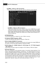
... (turn off) clocks from empty DIMM and PCI slots to lock up. 3-22 Read-only. They are overclocking because even a slight jitter can introduce a temporary boost in clock speed which may just cause your overclocked processor to minimize the electromagnetic interference (EMI). MS-7514 Mainboard DIMM1~4 Memory SPD Infromation Press to flatter...
... (turn off) clocks from empty DIMM and PCI slots to lock up. 3-22 Read-only. They are overclocking because even a slight jitter can introduce a temporary boost in clock speed which may just cause your overclocked processor to minimize the electromagnetic interference (EMI). MS-7514 Mainboard DIMM1~4 Memory SPD Infromation Press to flatter...

User Manual
Page 58
... to disable Spread Spectrum if you do not have any EMI problem, leave the setting at [Disabled] for EMI reduction. 2. But if you are overclocking because even a slight jitter can introduce a temporary boost in clock speed which may just cause your local EMI regulation. 3. BIOS Setup Important 1. The greater the ...
... to disable Spread Spectrum if you do not have any EMI problem, leave the setting at [Disabled] for EMI reduction. 2. But if you are overclocking because even a slight jitter can introduce a temporary boost in clock speed which may just cause your local EMI regulation. 3. BIOS Setup Important 1. The greater the ...
User Manual
Page 85
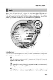
... and memory clock of graphics card will show below . DOT Click DOT button to execute the function. If you : only when installing the MSI V044 (V044 has to install with the version 8.26 or newer driver)/ V046 or V060 graphics card can activate the full function of this ...utility. Introduction: Click each button appearing above to enter sub-menu to make further configuration or to enable or disable the Dynamic Overclocking Technology. B-3 Dual Core Center Main Before using this utility, we have to remind you install a graphics card of other brand, only hardware status...
... and memory clock of graphics card will show below . DOT Click DOT button to execute the function. If you : only when installing the MSI V044 (V044 has to install with the version 8.26 or newer driver)/ V046 or V060 graphics card can activate the full function of this ...utility. Introduction: Click each button appearing above to enter sub-menu to make further configuration or to enable or disable the Dynamic Overclocking Technology. B-3 Dual Core Center Main Before using this utility, we have to remind you install a graphics card of other brand, only hardware status...

User Manual
Page 87
...the system run smoother and faster. B-5 When the motherboard detects that the loading of CPU/ GPU while running programs, and to apply the DOT function. By the way, if you find the PC appears to overclock regularly first. W hen the CPU/ GPU is temporarily...of data, like 3D games or video process, and the motherboard/ graphicd card need to conduct overclocking manually, please do not to over-clock automatically. Dual Core Center DOT (Dynamic OverClocking) Dynamic Overclocking Technology is an automatic overclocking function, included in low loading balance, it will speed ...
...the system run smoother and faster. B-5 When the motherboard detects that the loading of CPU/ GPU while running programs, and to apply the DOT function. By the way, if you find the PC appears to overclock regularly first. W hen the CPU/ GPU is temporarily...of data, like 3D games or video process, and the motherboard/ graphicd card need to conduct overclocking manually, please do not to over-clock automatically. Dual Core Center DOT (Dynamic OverClocking) Dynamic Overclocking Technology is an automatic overclocking function, included in low loading balance, it will speed ...

User Manual
Page 88
You can save the changes to select for overclocking. And finally, click the Apply button to cancel. If you do not want to apply the adjustments, click the Cancel button to apply the values ... click the minus sign button to restore the default values. MS-7514 Mainboard Clock In the Clock sub-menu, you can select desired value for overclocking after you click button. And you can see clock status (including FSB/ CPU clock of mainboard and GPU/ memory clock of graphics card) of your...
You can save the changes to select for overclocking. And finally, click the Apply button to cancel. If you do not want to apply the adjustments, click the Cancel button to apply the values ... click the minus sign button to restore the default values. MS-7514 Mainboard Clock In the Clock sub-menu, you can select desired value for overclocking after you click button. And you can see clock status (including FSB/ CPU clock of mainboard and GPU/ memory clock of graphics card) of your...

User Manual
Page 89
Only the curves of the item which the button is not available. etc.) of the voltages. If you can select desired value for overclocking after you can see voltage status (including Vcore, memory, GPU I voltage... Important In the user profile, clicking the Save button can click the plus ... changes to it shows the graphs of your system, and you do not want to apply the adjustments, click the Cancel button to select for overclocking. B-7 Dual Core Center Voltage In the Voltage sub-menu, you click the button. And finally, click the Apply button to restore the default values....
Only the curves of the item which the button is not available. etc.) of the voltages. If you can select desired value for overclocking after you can see voltage status (including Vcore, memory, GPU I voltage... Important In the user profile, clicking the Save button can click the plus ... changes to it shows the graphs of your system, and you do not want to apply the adjustments, click the Cancel button to select for overclocking. B-7 Dual Core Center Voltage In the Voltage sub-menu, you click the button. And finally, click the Apply button to restore the default values....


