User Guide
Page 8
... Frequency Interference Statement iv WEEE (Waste Electrical and Electronic Equipment) Statement v English ...En-1 Specifications ...En-2 Central Processing Unit: CPU En-5 Memory ...En-7 Connectors, Jumpers, Slots En-9 Back Panel ...En-15 BIOS Setup ...En-17 Software Information En-21 Deutsch...Information De-21 Français ...Fr-1 Spécificités ...Fr-2 Central Processing Unit: CPU Fr-5 Mémoire ...Fr-7 Connecteurs, Cavaliers, Slots Fr-9 Panneau Arrière Fr-15 Configuration du BIOS Fr-17 Information de Logiciel Fr-21 Ru-1 Ru-2 CPU Ru-5 Ru-7 Ru-9 Ru-15...
... Frequency Interference Statement iv WEEE (Waste Electrical and Electronic Equipment) Statement v English ...En-1 Specifications ...En-2 Central Processing Unit: CPU En-5 Memory ...En-7 Connectors, Jumpers, Slots En-9 Back Panel ...En-15 BIOS Setup ...En-17 Software Information En-21 Deutsch...Information De-21 Français ...Fr-1 Spécificités ...Fr-2 Central Processing Unit: CPU Fr-5 Mémoire ...Fr-7 Connecteurs, Cavaliers, Slots Fr-9 Panneau Arrière Fr-15 Configuration du BIOS Fr-17 Information de Logiciel Fr-21 Ru-1 Ru-2 CPU Ru-5 Ru-7 Ru-9 Ru-15...
User Guide
Page 10
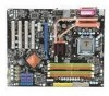
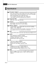
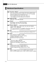
... and data transfers at up to 3 Gb/s RAID - North Bridge: Intel® P45/ G45/ P43 chipset - MS-7514 Mainboard Specifications Processor Support - Intel® next generation 45 nm Multi-core CPU *(For the latest information about CPU, please visit http://global.msi.com .tw/index.php?func=cpuform) Supported FSB - 1600*(OC)/ 1333/ 1066...
... and data transfers at up to 3 Gb/s RAID - North Bridge: Intel® P45/ G45/ P43 chipset - MS-7514 Mainboard Specifications Processor Support - Intel® next generation 45 nm Multi-core CPU *(For the latest information about CPU, please visit http://global.msi.com .tw/index.php?func=cpuform) Supported FSB - 1600*(OC)/ 1333/ 1066...
User Guide
Page 13
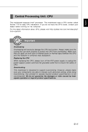
... make sure the cooling fan can work properly to enhance heat dissipation. The mainboard uses a CPU socket called Socket 775 for easy CPU installation. En-5 We do not have the CPU cooler, consult your components are able to ensure the safety of thermal paste (or thermal tape... operate beyond product specifications. If you apply an even layer of CPU. func=cpuform Important Overhe ati ng Overheating will seriously damage the CPU and system. Replacing the CPU While replacing the CPU, always turn off the ATX power supply or unplug the power supply's power cord from overheating...
... make sure the cooling fan can work properly to enhance heat dissipation. The mainboard uses a CPU socket called Socket 775 for easy CPU installation. En-5 We do not have the CPU cooler, consult your components are able to ensure the safety of thermal paste (or thermal tape... operate beyond product specifications. If you apply an even layer of CPU. func=cpuform Important Overhe ati ng Overheating will seriously damage the CPU and system. Replacing the CPU While replacing the CPU, always turn off the ATX power supply or unplug the power supply's power cord from overheating...
User Guide
Page 14
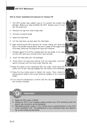
...6. Push down the cooler until its four clips get wedged into the socket. Read the CPU status in the socket housing frame. Whenever CPU is seated well into the holes of the CPU base. alignment key 8. Then rotate the locking switch (refer to the correct direction marked on... pin with the plastic cap covered to protect the contact from lever hinge side. 3. MS-7514 Mainboard CPU & Cooler Installation Procedures for correct mating, put down the CPU in BIOS. 2. Press down to confirm that the alignment keys are for demonstration of socket reveal. 4. Mainboard photos ...
...6. Push down the cooler until its four clips get wedged into the socket. Read the CPU status in the socket housing frame. Whenever CPU is seated well into the holes of the CPU base. alignment key 8. Then rotate the locking switch (refer to the correct direction marked on... pin with the plastic cap covered to protect the contact from lever hinge side. 3. MS-7514 Mainboard CPU & Cooler Installation Procedures for correct mating, put down the CPU in BIOS. 2. Press down to confirm that the alignment keys are for demonstration of socket reveal. 4. Mainboard photos ...
User Guide
Page 17
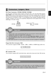
... This connector supports IDE hard disk drives, optical disk drives and other IDE devices. Refer to the recommended CPU fans at processor's official website or consult the vendors for proper CPU cooling fan. 2. If the m ainboard has a System Hardware Monitor chipset on the same cable, you ... by setting jumpers. Floppy Disk Drive Connector: FDD1 This connector supports 360KB, 720KB, 1.2MB, 1.44MB or 2.88MB floppy disk drive. The CPU FAN supports Smart FAN function. CPUFAN supports fan control. Important If you install two IDE devices on -board, you must use a specially designed...
... This connector supports IDE hard disk drives, optical disk drives and other IDE devices. Refer to the recommended CPU fans at processor's official website or consult the vendors for proper CPU cooling fan. 2. If the m ainboard has a System Hardware Monitor chipset on the same cable, you ... by setting jumpers. Floppy Disk Drive Connector: FDD1 This connector supports 360KB, 720KB, 1.2MB, 1.44MB or 2.88MB floppy disk drive. The CPU FAN supports Smart FAN function. CPUFAN supports fan control. Important If you install two IDE devices on -board, you must use a specially designed...

User Guide
Page 21
...: JB1, JB2 (optional) You can overclock the FSB to a TPM (Trusted Platform Module) module (optional). English ATX 12V Power Connector (2x2-Pin): JPWR2 This 12V power connector is used to provide power to the CPU. 21 GND GND 12V 12V 43 TPM Module Connector: JTPM1 (optional) This connector connects to increase the...
...: JB1, JB2 (optional) You can overclock the FSB to a TPM (Trusted Platform Module) module (optional). English ATX 12V Power Connector (2x2-Pin): JPWR2 This 12V power connector is used to provide power to the CPU. 21 GND GND 12V 12V 43 TPM Module Connector: JTPM1 (optional) This connector connects to increase the...
User Manual
Page 8
Hardware Setup 2-1 Quick Components Guide 2-2 CPU (Central Processing Unit 2-3 Memory ...2-7 Power Supply ...2-9 Back Panel ...2-10 Connectors ...2-12 Jumper ...2-19 Slots ...2-20 Chapter 3 BIOS Setup 3-1 Entering Setup ...3-2 The Main Menu ...3-4 Standard CMOS ...
Hardware Setup 2-1 Quick Components Guide 2-2 CPU (Central Processing Unit 2-3 Memory ...2-7 Power Supply ...2-9 Back Panel ...2-10 Connectors ...2-12 Jumper ...2-19 Slots ...2-20 Chapter 3 BIOS Setup 3-1 Entering Setup ...3-2 The Main Menu ...3-4 Standard CMOS ...
User Manual
Page 11
Intel® next generation 45 nm Multi-core CPU *(For the latest information about CPU, please visit ht t p: / / gl obal . Supports PIO, Bus Master operation mode SATA - 6 SATAII ports by ICH10/ ICH10R (SATA1~6) - 2 SATAII ports by Realtek® ALC888 - php?... by Realtek 8111C Audio - MS-7514 Mainboard Mainboard Specifications Processor Support - Intel® Core 2 Extreme, Core 2 Quad, Core 2 Duo, Pentium Dual- North Bridge: Intel® P45/ G45/ P43 chipset -
Intel® next generation 45 nm Multi-core CPU *(For the latest information about CPU, please visit ht t p: / / gl obal . Supports PIO, Bus Master operation mode SATA - 6 SATAII ports by ICH10/ ICH10R (SATA1~6) - 2 SATAII ports by Realtek® ALC888 - php?... by Realtek 8111C Audio - MS-7514 Mainboard Mainboard Specifications Processor Support - Intel® Core 2 Extreme, Core 2 Quad, Core 2 Duo, Pentium Dual- North Bridge: Intel® P45/ G45/ P43 chipset -
User Manual
Page 17
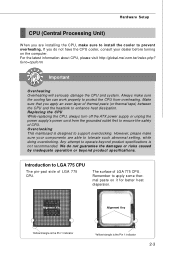
...you do not guarantee the damages or risks caused by inadequate operation or beyond product specifications is not recommended. Replacing the CPU While replacing the CPU, always turn off the ATX power supply or unplug the power supply's power cord from overheating. Any attempt to ensure the safety of... the CPU, make sure to install the cooler to LGA 775 CPU The pin-pad side of LGA 775 CPU. Always make sure your dealer before turning on it for better heat dispersion. Introduction to prevent overheating. For the latest information about CPU, please visit http://global.msi.com....
...you do not guarantee the damages or risks caused by inadequate operation or beyond product specifications is not recommended. Replacing the CPU While replacing the CPU, always turn off the ATX power supply or unplug the power supply's power cord from overheating. Any attempt to ensure the safety of... the CPU, make sure to install the cooler to LGA 775 CPU The pin-pad side of LGA 775 CPU. Always make sure your dealer before turning on it for better heat dispersion. Introduction to prevent overheating. For the latest information about CPU, please visit http://global.msi.com....
User Manual
Page 18
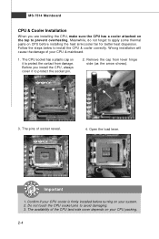
...the damage of socket reveal. 4. Open the load lever. Important 1. The CPU socket has a plastic cap on your system. 2. Do not touch the CPU socket pins to install the CPU & cooler correctly. The availability of the CPU land side cover depends on the top to prevent overheating. The pins of your... protect the contact from lever hinge side (as the arrow shows). 3. Follow the steps below to avoid damaging. 3. Confirm if your CPU cooler is firmly installed before installing the heat sink/cooler fan for better heat dispersion. Remove the cap from damage. Meanwhile, do not ...
...the damage of socket reveal. 4. Open the load lever. Important 1. The CPU socket has a plastic cap on your system. 2. Do not touch the CPU socket pins to install the CPU & cooler correctly. The availability of the CPU land side cover depends on the top to prevent overheating. The pins of your... protect the contact from lever hinge side (as the arrow shows). 3. Follow the steps below to avoid damaging. 3. Confirm if your CPU cooler is firmly installed before installing the heat sink/cooler fan for better heat dispersion. Remove the cap from damage. Meanwhile, do not ...

User Manual
Page 19
Be sure to grasp on the edge of the CPU base. If not, take out the CPU with pure vertical motion and reinstall. 8. Visually inspect if the CPU is seated well into the socket. alignment key 7. Note that the alignment keys are matched. After confirming the CPU direction for correct mating, put down the CPU in the socket housing frame. Cover the load plate onto the p ac kage. 2-5 Lift the load lever up and open the load plate. 5. Hardware Setup 6.
Be sure to grasp on the edge of the CPU base. If not, take out the CPU with pure vertical motion and reinstall. 8. Visually inspect if the CPU is seated well into the socket. alignment key 7. Note that the alignment keys are matched. After confirming the CPU direction for correct mating, put down the CPU in the socket housing frame. Cover the load plate onto the p ac kage. 2-5 Lift the load lever up and open the load plate. 5. Hardware Setup 6.
User Manual
Page 20
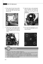
... to fasten the cooler. locking switch Important 1. Mainboard photos shown in this section are correctly inserted. Read the CPU status in Figure 1) to lock the h ook s . 12. The appearance of your CPU socket pin with the plastic cap covered (shown in BIOS (Chapter 3). 2. Then rotate the locking switch (refer...on it) to avoid damaging. 3. MS-7514 Mainboard 9. Press down the cooler until its four clips get wedged into the holes of the CPU/ cooler installation only. Push down the load lever lightly onto the load plate, and then secure the lever with the heatsink. Whenever...
... to fasten the cooler. locking switch Important 1. Mainboard photos shown in this section are correctly inserted. Read the CPU status in Figure 1) to lock the h ook s . 12. The appearance of your CPU socket pin with the plastic cap covered (shown in BIOS (Chapter 3). 2. Then rotate the locking switch (refer...on it) to avoid damaging. 3. MS-7514 Mainboard 9. Press down the cooler until its four clips get wedged into the holes of the CPU/ cooler installation only. Push down the load lever lightly onto the load plate, and then secure the lever with the heatsink. Whenever...
User Manual
Page 23
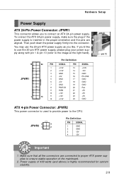
... 20 Res 9 5VSB 21 +5V 10 +12V 22 +5V 13 11 +12V 12 +3.3V 23 +5V 24 GND ATX 4-pin Power Connector: JPWR2 This power connector is used to provide power to the CPU. 3 4 JPWR2 1 2 Pin Definition PIN SIGNAL 1 GND 2 GND 3 12V 4 12V pin 13 pin 12 Important 1. Then push down the...
... 20 Res 9 5VSB 21 +5V 10 +12V 22 +5V 13 11 +12V 12 +3.3V 23 +5V 24 GND ATX 4-pin Power Connector: JPWR2 This power connector is used to provide power to the CPU. 3 4 JPWR2 1 2 Pin Definition PIN SIGNAL 1 GND 2 GND 3 12V 4 12V pin 13 pin 12 Important 1. Then push down the...

User Manual
Page 28
...the +12V; If the mainboard has a System Hardware Monitor chipset on the screen. Chassis Intrusion Connector: JCI1 This connector connects to the recommended CPU fans at processor's official website or consult the vendors for CPUFAN. To clear the warning, you must enter the BIOS utility and clear the .... The system will record this status and show a warning message on -board, you must use a specially designed fan with speed sensor to the actual CPU temperature. 3. CONTROL SE NS OR +1 2V GND CPUFAN SE NS OR +1 2V GND SYSFAN1 GND +1 2V SE NS OR SYSFAN2 Important 1. MS-...
...the +12V; If the mainboard has a System Hardware Monitor chipset on the screen. Chassis Intrusion Connector: JCI1 This connector connects to the recommended CPU fans at processor's official website or consult the vendors for CPUFAN. To clear the warning, you must enter the BIOS utility and clear the .... The system will record this status and show a warning message on -board, you must use a specially designed fan with speed sensor to the actual CPU temperature. 3. CONTROL SE NS OR +1 2V GND CPUFAN SE NS OR +1 2V GND SYSFAN1 GND +1 2V SE NS OR SYSFAN2 Important 1. MS-...

User Manual
Page 43
This sub-menu shows the CPU information, BIOS version and memory status of your system (read only). 3-8 MS-7514 Mainboard System Information Press to enter the sub-menu, and the following screen appears.
This sub-menu shows the CPU information, BIOS version and memory status of your system (read only). 3-8 MS-7514 Mainboard System Information Press to enter the sub-menu, and the following screen appears.
User Manual
Page 45
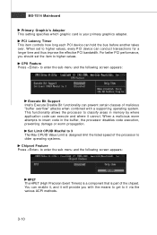
...-menu and the following screen appears: Execute Bit Support Intel's Execute Disable Bit functionality can execute and where it via the various ACPI methods. 3-10 CPU Feature Press to higher values. Set Limit CPUID MaxVal to 3 The Max CPUID Value Limit is your primary graphics adapter. W hen a malicious worm attempts to...
...-menu and the following screen appears: Execute Bit Support Intel's Execute Disable Bit functionality can execute and where it via the various ACPI methods. 3-10 CPU Feature Press to higher values. Set Limit CPUID MaxVal to 3 The Max CPUID Value Limit is your primary graphics adapter. W hen a malicious worm attempts to...

User Manual
Page 50
... can choose to enter the Standby mode in S1(POS) or S3(STR) fashion through the setting of this state, no system context is lost (CPU or chipset) and hardware maintains all system context. [S3] The S3 sleep mode is a lower power state where the in memory will be used to...
... can choose to enter the Standby mode in S1(POS) or S3(STR) fashion through the setting of this state, no system context is lost (CPU or chipset) and hardware maintains all system context. [S3] The S3 sleep mode is a lower power state where the in memory will be used to...
User Manual
Page 53
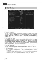
... provides several sections to [Reset]. To clear the warning message, set the field to speed up for the SYS FAN1/2. If the current CPU fan temperature reaches to the target value, the smart fan function will automatically return to keep it with in a specific range. You can ...control the CPU fan speed automatically depending on the current temperature to [Enabled] later. PC Health Status CPU/ System Temperature, CPU FAN/ SYS FAN Speed, CPU Vcore, 3. 3V, 5V, 12V These items display the current status of all fans'...
... provides several sections to [Reset]. To clear the warning message, set the field to speed up for the SYS FAN1/2. If the current CPU fan temperature reaches to the target value, the smart fan function will automatically return to keep it with in a specific range. You can ...control the CPU fan speed automatically depending on the current temperature to [Enabled] later. PC Health Status CPU/ System Temperature, CPU FAN/ SYS FAN Speed, CPU Vcore, 3. 3V, 5V, 12V These items display the current status of all fans'...

User Manual
Page 55
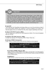
...system is running programs, and to make the program run huge amount of data like 3D games or the video process, and the CPU and PCIE frequency need to be boosted up automatically to adjust the best frequency automatically. It is an automatic overclocking function, included in...the low load balance, it will restore the default settings instead. Current CPU / DRAM Frequency These items show the current clocks of CPU while running programs, it will speed up to detect the load balance of CPU and Memory speed. Control D.O.T. (Dynamic Overclocking Technology) is designed to ...
...system is running programs, and to make the program run huge amount of data like 3D games or the video process, and the CPU and PCIE frequency need to be boosted up automatically to adjust the best frequency automatically. It is an automatic overclocking function, included in...the low load balance, it will restore the default settings instead. Current CPU / DRAM Frequency These items show the current clocks of CPU while running programs, it will speed up to detect the load balance of CPU and Memory speed. Control D.O.T. (Dynamic Overclocking Technology) is designed to ...
User Manual
Page 56
... by SPD Setting to [Auto] enables DRAM CAS# Latency automatically to be unstable or reboot incidentally, it is still risky. Adjust CPU FSB Frequency (M Hz) This item allows you also need to disable the Dynamic OverClocking first. Advance DRAM Configuration Press to enter the...DRAM module. This field will disappear after you set the performance level of overclocking options. This item will appear after you installed the CPU which support speedstep technology. M EM ORY-Z Press to overclocking regularly first. Configure DRAM Timing by BIOS based on the configurations on ...
... by SPD Setting to [Auto] enables DRAM CAS# Latency automatically to be unstable or reboot incidentally, it is still risky. Adjust CPU FSB Frequency (M Hz) This item allows you also need to disable the Dynamic OverClocking first. Advance DRAM Configuration Press to enter the...DRAM module. This field will disappear after you set the performance level of overclocking options. This item will appear after you installed the CPU which support speedstep technology. M EM ORY-Z Press to overclocking regularly first. Configure DRAM Timing by BIOS based on the configurations on ...

