
User Guide
Page 4
... DE RACCORDER AU RESEAU. power cord, if any interference received, including interference that may cause harmful interference to operate the equipment. iv Micro-Star International MS-7514 This device complies with Part 15 of the FCC Rules. Notice 2 Shielded interface cables and A.C. FCC-B Radio Frequency Interference Statement T h is eq uip men...
... DE RACCORDER AU RESEAU. power cord, if any interference received, including interference that may cause harmful interference to operate the equipment. iv Micro-Star International MS-7514 This device complies with Part 15 of the FCC Rules. Notice 2 Shielded interface cables and A.C. FCC-B Radio Frequency Interference Statement T h is eq uip men...
User Guide
Page 10
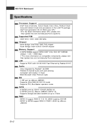
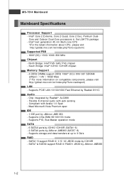
... mode by Realtek® ALC888 - North Bridge: Intel® P45/ G45/ P43 chipset - Supports Ultra DMA 66/100/133 m ode - Supports PCIE LAN 10/100/1000 Fast Ethernet by JMicron JMB363 - Com pliant with jack sensing - MS-7514 Mainboard Specifications Processor Support - Meet Microsoft Vista Premium spec IDE...index.php?func=testreport) LAN - Intel® next generation 45 nm Multi-core CPU *(For the latest information about CPU, please visit http://global.msi.com .tw/index.php?func=cpuform) Supported FSB - 1600*(OC)/ 1333/ 1066/ 800 MHz Chipset - Intel® Core 2 Extreme, Core ...
... mode by Realtek® ALC888 - North Bridge: Intel® P45/ G45/ P43 chipset - Supports Ultra DMA 66/100/133 m ode - Supports PCIE LAN 10/100/1000 Fast Ethernet by JMicron JMB363 - Com pliant with jack sensing - MS-7514 Mainboard Specifications Processor Support - Meet Microsoft Vista Premium spec IDE...index.php?func=testreport) LAN - Intel® next generation 45 nm Multi-core CPU *(For the latest information about CPU, please visit http://global.msi.com .tw/index.php?func=cpuform) Supported FSB - 1600*(OC)/ 1333/ 1066/ 800 MHz Chipset - Intel® Core 2 Extreme, Core ...
User Guide
Page 14
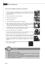
... this section are for Socket 775 1. Remove the cap from damage. Open the load lever. 5. Be sure to grasp on it to fasten the cooler. MS-7514 Mainboard CPU & Cooler Installation Procedures for demonstration of the CPU/ cooler installation only. If not, take out the CPU with the plastic cap covered...
... this section are for Socket 775 1. Remove the cap from damage. Open the load lever. 5. Be sure to grasp on it to fasten the cooler. MS-7514 Mainboard CPU & Cooler Installation Procedures for demonstration of the CPU/ cooler installation only. If not, take out the CPU with the plastic cap covered...
User Guide
Page 16
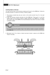
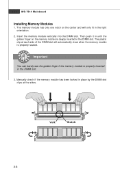
... at i on the memory module is properly seated. The memory module has only one notch on the DIMM slot. The plastic clip at the sides. MS-7514 Mainboard Installing Memory Modules You can barely see the golden finger if the memory module is properly inserted in the DIMM slot. Volt Notch...
... at i on the memory module is properly seated. The memory module has only one notch on the DIMM slot. The plastic clip at the sides. MS-7514 Mainboard Installing Memory Modules You can barely see the golden finger if the memory module is properly inserted in the DIMM slot. Volt Notch...
User Guide
Page 18
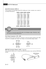
...+ Ground TPB+ Cable power Key(no pin) En-10 Front Panel Connectors: JFP1, JFP2 These connectors are for electrical connection to one Serial ATA device. MS-7514 Mainboard Serial ATA Connector: SATA1~8 This connector is compliant with Intel® Front Panel I/O Connectivity Design Guide. Each connector can connect to the front...
...+ Ground TPB+ Cable power Key(no pin) En-10 Front Panel Connectors: JFP1, JFP2 These connectors are for electrical connection to one Serial ATA device. MS-7514 Mainboard Serial ATA Connector: SATA1~8 This connector is compliant with Intel® Front Panel I/O Connectivity Design Guide. Each connector can connect to the front...
User Guide
Page 20
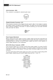
... GND +3.3V GND -12V +3.3V +3.3V 1 13 En-12 R GND L Chassis Intrusion Connector: JCI1 This connector connects to connect an ATX 24-pin power supply. ATX 24-Pin Power Connector: JPWR1 This connector allows you must enter the BIOS utility and clear the record. 1 CINTRU 2 GND Power Supply Attachment... inserting the power supply connector, always make sure the plug of the m ainboard. To connect the ATX 24-pin power supply, make sure that no damage will be activated. MS-7514 Mainboard CD-In Connector: JCD1 This connector is inserted in the proper orientation and the pins are...
... GND +3.3V GND -12V +3.3V +3.3V 1 13 En-12 R GND L Chassis Intrusion Connector: JCI1 This connector connects to connect an ATX 24-pin power supply. ATX 24-Pin Power Connector: JPWR1 This connector allows you must enter the BIOS utility and clear the record. 1 CINTRU 2 GND Power Supply Attachment... inserting the power supply connector, always make sure the plug of the m ainboard. To connect the ATX 24-pin power supply, make sure that no damage will be activated. MS-7514 Mainboard CD-In Connector: JCD1 This connector is inserted in the proper orientation and the pins are...
User Guide
Page 22
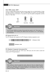
... LAN card, SCSI card, USB card, and other add-on ; Avoid clearing the CMOS while the system is on cards that comply with PCI specifications. MS-7514 Mainboard Clear CMOS Jumper: JBAT1 There is a CMOS RAM onboard that has a power supply from an external battery to clear data. 1 JBAT1 1 1 3 Keep Data...
... LAN card, SCSI card, USB card, and other add-on ; Avoid clearing the CMOS while the system is on cards that comply with PCI specifications. MS-7514 Mainboard Clear CMOS Jumper: JBAT1 There is a CMOS RAM onboard that has a power supply from an external battery to clear data. 1 JBAT1 1 1 3 Keep Data...
User Guide
Page 24
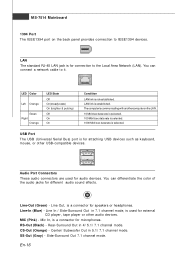
... Mbit/sec data rate is for external CD player, tape player or other USB-com patible devices. CS-Out (Orange) - Side-Surround Out 7.1 channel m ode. MS-7514 Mainboard 1394 Port The IEEE1394 port on the back panel provides connection to the Local Area Network (LAN). Line-In (Blue) - Rear-Surround Out...
... Mbit/sec data rate is for external CD player, tape player or other USB-com patible devices. CS-Out (Orange) - Side-Surround Out 7.1 channel m ode. MS-7514 Mainboard 1394 Port The IEEE1394 port on the back panel provides connection to the Local Area Network (LAN). Line-In (Blue) - Rear-Surround Out...

User Guide
Page 25
... refers to the model number. 6th refers to the Chipset vender as A = AMD, I = Intel, V = VIA, N = Nvidia, U = ULi. 7th - 8th digit refers to the customer as MS = all standard customers. Therefore, the description may need to run the Setup program when: * An error message appears on the BIOS Setup program and allows...
... refers to the model number. 6th refers to the Chipset vender as A = AMD, I = Intel, V = VIA, N = Nvidia, U = ULi. 7th - 8th digit refers to the customer as MS = all standard customers. Therefore, the description may need to run the Setup program when: * An error message appears on the BIOS Setup program and allows...
User Guide
Page 26
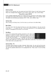
... you will start POST (Power On Self Test) process. General Help The BIOS setup program provides a General Help screen. Press to field within a sub-menu. MS-7514 Mainboard Entering Setup Power on the computer and the system will see is displayed at the bottom of certain fields that means a sub-menu...
... you will start POST (Power On Self Test) process. General Help The BIOS setup program provides a General Help screen. Press to field within a sub-menu. MS-7514 Mainboard Entering Setup Power on the computer and the system will see is displayed at the bottom of certain fields that means a sub-menu...
User Guide
Page 28
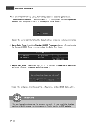
MS-7514 Mainboard W hen enter the BIOS Setup utility, follow the processes below for general use only. Save & Exit Setup : Use control keys (↑↓ ) to ... . 1. Important The configuration above are for optimal system performance. 2. If you need the detailed settings of BIOS, please see the manual in English version on MSI website.
MS-7514 Mainboard W hen enter the BIOS Setup utility, follow the processes below for general use only. Save & Exit Setup : Use control keys (↑↓ ) to ... . 1. Important The configuration above are for optimal system performance. 2. If you need the detailed settings of BIOS, please see the manual in English version on MSI website.

User Manual
Page 4
... is encouraged to try to correct the interference by the party responsible for compliance could void the user's authority to radio communications. Micro-Star International MS-7514 This device complies with the limits for help. VOIR LANOTICE D'INSTALLATIONAVANT DE RACCORDER AU RESEAU. However, there is eq uip men t h as been tested...
... is encouraged to try to correct the interference by the party responsible for compliance could void the user's authority to radio communications. Micro-Star International MS-7514 This device complies with the limits for help. VOIR LANOTICE D'INSTALLATIONAVANT DE RACCORDER AU RESEAU. However, there is eq uip men t h as been tested...
User Manual
Page 10
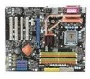
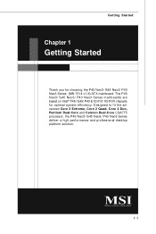
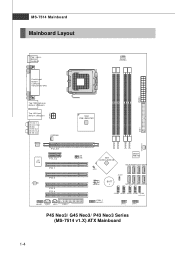
Getting Started Chapter 1 Getting Started Thank you for optimal system efficiency. Designed to fit the advanced Core 2 Extreme, Core 2 Quad, Core 2 Duo, Pentium Dual-Core and Celeron Dual-Core LGA775 processor, the P45 Neo3/ G45 Neo3/ P43 Neo3 Series deliver a high performance and professional desktop platform solution. 1-1 The P45 Neo3/ G45 Neo3/ P43 Neo3 Series mainboards are based on Intel® P45/ G45/ P43 & ICH10/ ICH10R chipsets for choosing the P45 Neo3/ G45 Neo3/ P43 Neo3 Series (MS-7514 v1.X) ATX mainboard.
Getting Started Chapter 1 Getting Started Thank you for optimal system efficiency. Designed to fit the advanced Core 2 Extreme, Core 2 Quad, Core 2 Duo, Pentium Dual-Core and Celeron Dual-Core LGA775 processor, the P45 Neo3/ G45 Neo3/ P43 Neo3 Series deliver a high performance and professional desktop platform solution. 1-1 The P45 Neo3/ G45 Neo3/ P43 Neo3 Series mainboards are based on Intel® P45/ G45/ P43 & ICH10/ ICH10R chipsets for choosing the P45 Neo3/ G45 Neo3/ P43 Neo3 Series (MS-7514 v1.X) ATX mainboard.
User Manual
Page 11
... nm Multi-core CPU *(For the latest information about CPU, please visit ht t p: / / gl obal . North Bridge: Intel® P45/ G45/ P43 chipset - Supports storage and data transfers at up to 3 Gb/s RAID - MS-7514 Mainboard Mainboard Specifications Processor Support - c om . Compliant with jack sensing - Flexible 8-channel audio with Azalia 1.0 Spec - m si...
... nm Multi-core CPU *(For the latest information about CPU, please visit ht t p: / / gl obal . North Bridge: Intel® P45/ G45/ P43 chipset - Supports storage and data transfers at up to 3 Gb/s RAID - MS-7514 Mainboard Mainboard Specifications Processor Support - c om . Compliant with jack sensing - Flexible 8-channel audio with Azalia 1.0 Spec - m si...
User Manual
Page 13
... SATA2 SATA8 JBAT1 JMicron JMB 381 (optional) BATT + SATA5 SATA3 SATA1 SATA7 J1394_1 (o pt ional ) J USB4 J USB3 JUSB2 JUSB1 J TPM1 (opt io nal) JFP2 JFP1 P45 Neo3/ G45 Neo3/ P43 Neo3 Series (MS-7514 v1.X) ATX Mainboard 1-4 Ou t B:SS-Out SYSFAN2 Realtek 8111C PCI_E1 I n M:Line-Out B:Mic T: RS -Out M :CS-
... SATA2 SATA8 JBAT1 JMicron JMB 381 (optional) BATT + SATA5 SATA3 SATA1 SATA7 J1394_1 (o pt ional ) J USB4 J USB3 JUSB2 JUSB1 J TPM1 (opt io nal) JFP2 JFP1 P45 Neo3/ G45 Neo3/ P43 Neo3 Series (MS-7514 v1.X) ATX Mainboard 1-4 Ou t B:SS-Out SYSFAN2 Realtek 8111C PCI_E1 I n M:Line-Out B:Mic T: RS -Out M :CS-
User Manual
Page 18
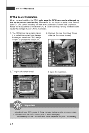
... damage of your CPU packing. 2-4 The CPU socket has a plastic cap on it to apply some thermal paste on CPU before turning on your system. 2. MS-7514 Mainboard CPU & Cooler Installation W hen you install the CPU, always cover it to prevent overheating. Remove the cap from damage. Meanwhile, do not forget...
... damage of your CPU packing. 2-4 The CPU socket has a plastic cap on it to apply some thermal paste on CPU before turning on your system. 2. MS-7514 Mainboard CPU & Cooler Installation W hen you install the CPU, always cover it to prevent overheating. Remove the cap from damage. Meanwhile, do not forget...
User Manual
Page 20
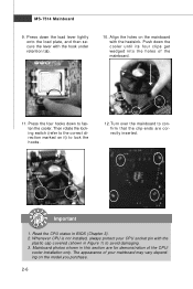
... model you purchase. 2-6 Read the CPU status in this section are correctly inserted. Mainboard photos shown in BIOS (Chapter 3). 2. The appearance of the mainboard. 11. MS-7514 Mainboard 9. locking switch Important 1. Press down the cooler until its four clips get wedged into the holes of your CPU socket pin with the...
... model you purchase. 2-6 Read the CPU status in this section are correctly inserted. Mainboard photos shown in BIOS (Chapter 3). 2. The appearance of the mainboard. 11. MS-7514 Mainboard 9. locking switch Important 1. Press down the cooler until its four clips get wedged into the holes of your CPU socket pin with the...
User Manual
Page 22
... by the DIMM slot clips at each side of the DIMM slot will only fit in the DIMM slot. The plastic clip at the sides. MS-7514 Mainboard Installing Memory Modules 1. Insert the memory module vertically into the DIMM slot. Manually check if the memory module has been locked in the...
... by the DIMM slot clips at each side of the DIMM slot will only fit in the DIMM slot. The plastic clip at the sides. MS-7514 Mainboard Installing Memory Modules 1. Insert the memory module vertically into the DIMM slot. Manually check if the memory module has been locked in the...

User Manual
Page 24
.../keyboard. Serial Port The serial port is a 16550A high speed communications port that supports Enhanced Parallel Port (EPP) and Extended Capabilities Parallel Port (ECP) mode. MS-7514 Mainboard Back Panel Mouse Parallel Port (optional) 1394 Port LAN Line-In RS-Out Line-Out CS-Out Keyboard Serial Port VGA Port (for...
.../keyboard. Serial Port The serial port is a 16550A high speed communications port that supports Enhanced Parallel Port (EPP) and Extended Capabilities Parallel Port (ECP) mode. MS-7514 Mainboard Back Panel Mouse Parallel Port (optional) 1394 Port LAN Line-In RS-Out Line-Out CS-Out Keyboard Serial Port VGA Port (for...

User Manual
Page 26
Refer to master / slave mode by the vendors for jumper setting instructions. 2-12 MS-7514 Mainboard Connectors Floppy Disk Drive Connector: FDD1 This connector supports 360KB, 720KB, 1.2MB, 1.44MB or 2.88MB floppy disk drive. Important If you install two IDE devices on the same cable, you must configure the drives separately to IDE device's documentation supplied by setting jumpers. IDE Connector: IDE1 This connector supports IDE hard disk drives, optical disk drives and other IDE devices.
Refer to master / slave mode by the vendors for jumper setting instructions. 2-12 MS-7514 Mainboard Connectors Floppy Disk Drive Connector: FDD1 This connector supports 360KB, 720KB, 1.2MB, 1.44MB or 2.88MB floppy disk drive. Important If you install two IDE devices on the same cable, you must configure the drives separately to IDE device's documentation supplied by setting jumpers. IDE Connector: IDE1 This connector supports IDE hard disk drives, optical disk drives and other IDE devices.


