
User Guide
Page 4
... limits for help. power cord, if any interference received, including interference that interference will not occur in order to operate the equipment. Micro-Star International MS-7516 This device complies with the instructions, may cause harmful interference to the following two conditions: (1) this device may cause undesired operation. Notice 2 Shielded interface cables...
... limits for help. power cord, if any interference received, including interference that interference will not occur in order to operate the equipment. Micro-Star International MS-7516 This device complies with the instructions, may cause harmful interference to the following two conditions: (1) this device may cause undesired operation. Notice 2 Shielded interface cables...

User Guide
Page 11
...*(OC)/ 1333/ 1066/ 800 MHz * (For the latest information about CPU, please visit http://global. North Bridge: Intel® P45 chipset - p hp?func =t est report ) LAN - Supports 1394 by Jmicron 363 - MS-7516 Mainboard Mainboard Specifications Processor Support - Supports Intel® CoreTM 2 Extreme/Quad/Duo/Pentium/Celeron Dual Core/Celeron processors. - Supports PCIE...
...*(OC)/ 1333/ 1066/ 800 MHz * (For the latest information about CPU, please visit http://global. North Bridge: Intel® P45 chipset - p hp?func =t est report ) LAN - Supports 1394 by Jmicron 363 - MS-7516 Mainboard Mainboard Specifications Processor Support - Supports Intel® CoreTM 2 Extreme/Quad/Duo/Pentium/Celeron Dual Core/Celeron processors. - Supports PCIE...

User Guide
Page 13
MS-7516 Mainboard Mainboard Layout PWR2 FDD 1 Top : mouse Bottom: keyboard PWR1 CP UFAN SYSFAN5 DIMM3 DIMM4 DIMM1 DIMM2 Top: US B ports Bottom: 1394 port eSATA port s SW1 Top: LAN Jack Bottom: USB p orts Top: LAN Jack Bottom: USB p orts SYSFA N4 PWR3 SYSFA N2 PCI _E1 PCI _E2 PCI _E3 JISI JB1 JB2 Intel P45 Intel I CH 10R J1395 SYSFAN3 SATA7 SATA8 SATA5_6 SATA2_4 SATA1_3 IDE 1 RESET_SW1 PCI _E4 PCI1 PCI2 J1 394_1 JFP2 BAT T + JCI1 JBAT1 JFP1 JUSB2 SW2 PWSW1 JUSB1 JCOM1 SYSFAN1 JTPM1 P45 Diamond Series (MS-7516 v1.X) ATX Mainboard 1-4
MS-7516 Mainboard Mainboard Layout PWR2 FDD 1 Top : mouse Bottom: keyboard PWR1 CP UFAN SYSFAN5 DIMM3 DIMM4 DIMM1 DIMM2 Top: US B ports Bottom: 1394 port eSATA port s SW1 Top: LAN Jack Bottom: USB p orts Top: LAN Jack Bottom: USB p orts SYSFA N4 PWR3 SYSFA N2 PCI _E1 PCI _E2 PCI _E3 JISI JB1 JB2 Intel P45 Intel I CH 10R J1395 SYSFAN3 SATA7 SATA8 SATA5_6 SATA2_4 SATA1_3 IDE 1 RESET_SW1 PCI _E4 PCI1 PCI2 J1 394_1 JFP2 BAT T + JCI1 JBAT1 JFP1 JUSB2 SW2 PWSW1 JUSB1 JCOM1 SYSFAN1 JTPM1 P45 Diamond Series (MS-7516 v1.X) ATX Mainboard 1-4

User Guide
Page 15
MS-7516 Mainboard SATA HDD Power Cable (For SATA to ESATA Bracket) (Optional) 6/8mm Adapter x 2 6/10mm Adapter x 2 6mm Clamp x 4 8mm Clamp x 2 10mm Clamp x 2 C Type Tubing Clip x 2 Tube x 2 (5mm internal diameter, 8mm outter diameter) GreenPower Genie Set (1 GreenPower genie & 1 power cable & 1 (2x2 pin) cable) X-Fi Xtreme Audio Card Set (Card and Driver CD) * The pictures are for reference only and may vary from the packing contents of the product you purchased. 1-6
MS-7516 Mainboard SATA HDD Power Cable (For SATA to ESATA Bracket) (Optional) 6/8mm Adapter x 2 6/10mm Adapter x 2 6mm Clamp x 4 8mm Clamp x 2 10mm Clamp x 2 C Type Tubing Clip x 2 Tube x 2 (5mm internal diameter, 8mm outter diameter) GreenPower Genie Set (1 GreenPower genie & 1 power cable & 1 (2x2 pin) cable) X-Fi Xtreme Audio Card Set (Card and Driver CD) * The pictures are for reference only and may vary from the packing contents of the product you purchased. 1-6

User Guide
Page 19
... protect the socket pin. 2. Before you are installing the CPU, make sure the CPU has a cooler attached on CPU before turning on your CPU & mainboard. 1. MS-7516 Mainboard CPU & Cooler Installation W hen you install the CPU, always cover it to protect the contact from lever hinge side (as the arrow shows). 3. Important...
... protect the socket pin. 2. Before you are installing the CPU, make sure the CPU has a cooler attached on CPU before turning on your CPU & mainboard. 1. MS-7516 Mainboard CPU & Cooler Installation W hen you install the CPU, always cover it to protect the contact from lever hinge side (as the arrow shows). 3. Important...

User Guide
Page 21
... photos shown in Figure 1) to confirm that the clip-ends are for demonstration of your CPU socket pin with the hook under retention tab. 10. MS-7516 Mainboard 9. Read the CPU status in BIOS (Chapter 3). 2. The appearance of the CPU/ cooler installation only.
... photos shown in Figure 1) to confirm that the clip-ends are for demonstration of your CPU socket pin with the hook under retention tab. 10. MS-7516 Mainboard 9. Read the CPU status in BIOS (Chapter 3). 2. The appearance of the CPU/ cooler installation only.

User Guide
Page 23
... right orientation. 2. Important You can barely see the golden finger if the memory module is properly inserted in different channel DIMM slots. - Volt Notch Important - MS-7516 Mainboard Installing Memory Modules 1. Insert the memory module vertically into the DIM M1 first. 2-8 The plastic clip at each side of the same type and...
... right orientation. 2. Important You can barely see the golden finger if the memory module is properly inserted in different channel DIMM slots. - Volt Notch Important - MS-7516 Mainboard Installing Memory Modules 1. Insert the memory module vertically into the DIM M1 first. 2-8 The plastic clip at each side of the same type and...

User Guide
Page 25
MS-7516 Mainboard DDR3 1066 Module Elpida EBJ11UD8BAFA-AC-E (Elpida J5308BASE-AC-E) Hynix HYMT112U64ZNF8-G7 (Hynix HY5TQ1G831ZNF-G7) Qimonda IMSH1GU13A1F1C-10F (Qimonda IDSH51-03A1F1C-10F) Qimonda IMSH1GU13A1F1C-...
MS-7516 Mainboard DDR3 1066 Module Elpida EBJ11UD8BAFA-AC-E (Elpida J5308BASE-AC-E) Hynix HYMT112U64ZNF8-G7 (Hynix HY5TQ1G831ZNF-G7) Qimonda IMSH1GU13A1F1C-10F (Qimonda IDSH51-03A1F1C-10F) Qimonda IMSH1GU13A1F1C-...

User Guide
Page 27
If you'd like . MS-7516 Mainboard Power Supply ATX 24-Pin Power Connector: PWR2 This connector allows you like to use the 20-pin ATX power supply as you to connect an ATX 24-pin power supply. To connect the ATX 24-pin power supply, make sure the plug of the power supply is used... for system stability. 2-12 Power supply of the mainboard. 2. Then push down the power supply firmly into the connector. You may use the 20-pin ATX power supply, please plug your power supply along with pin 1 & pin 13 (refer to the PCIEX16 graphics card. 4 8 1 5 PWR1 Pin Definition PIN ...
If you'd like . MS-7516 Mainboard Power Supply ATX 24-Pin Power Connector: PWR2 This connector allows you like to use the 20-pin ATX power supply as you to connect an ATX 24-pin power supply. To connect the ATX 24-pin power supply, make sure the plug of the power supply is used... for system stability. 2-12 Power supply of the mainboard. 2. Then push down the power supply firmly into the connector. You may use the 20-pin ATX power supply, please plug your power supply along with pin 1 & pin 13 (refer to the PCIEX16 graphics card. 4 8 1 5 PWR1 Pin Definition PIN ...

User Guide
Page 29
Important Make sure that has a power supply from external battery to keep the system configuration data. MS-7516 Mainboard Clear CMOS Button There is turned on board that you want to clear the system configuration, use the button to clear the data. If you power off the system before clearing CMOS data. 2-14 Press the button to clear data. With the CMOS RAM, the system can automatically boot OS every time it is a CMOS RAM on .
Important Make sure that has a power supply from external battery to keep the system configuration data. MS-7516 Mainboard Clear CMOS Button There is turned on board that you want to clear the system configuration, use the button to clear the data. If you power off the system before clearing CMOS data. 2-14 Press the button to clear data. With the CMOS RAM, the system can automatically boot OS every time it is a CMOS RAM on .

User Guide
Page 31
SATA3 SATA1 SATA4 SATA2 SATA6 SATA5 SATA1~6 supported by ICH10R SATA7 SATA8 supported by Jmicron 363 Important Please do not fold the Serial ATA cable into 90-degree angle. Otherwise, data loss may occur during transmission. 2-16 MS-7516 Mainboard Serial ATA Connector: SATA1 ~ SATA8 This connector is a high-speed Serial ATA interface port. Each connector can connect to one Serial ATA device.
SATA3 SATA1 SATA4 SATA2 SATA6 SATA5 SATA1~6 supported by ICH10R SATA7 SATA8 supported by Jmicron 363 Important Please do not fold the Serial ATA cable into 90-degree angle. Otherwise, data loss may occur during transmission. 2-16 MS-7516 Mainboard Serial ATA Connector: SATA1 ~ SATA8 This connector is a high-speed Serial ATA interface port. Each connector can connect to one Serial ATA device.

User Guide
Page 33
Please refer to connect the IEEE1394 device via an optional IEEE1394 bracket. MS-7516 Mainboard IEEE1394 Connector: J1394_1 This connector allows you to the TPM security platform manual for more details and usages. 2 14 1 13 JTPM 1 Pin Signal Description 1 ...
Please refer to connect the IEEE1394 device via an optional IEEE1394 bracket. MS-7516 Mainboard IEEE1394 Connector: J1394_1 This connector allows you to the TPM security platform manual for more details and usages. 2 14 1 13 JTPM 1 Pin Signal Description 1 ...

User Guide
Page 35
MS-7516 Mainboard Front USB Connector: JUSB1/2 These connectors, compliant with Intel® I/O Connectivity Design Guide, is a 16550A high speed communication port that the pins of VCC ...
MS-7516 Mainboard Front USB Connector: JUSB1/2 These connectors, compliant with Intel® I/O Connectivity Design Guide, is a 16550A high speed communication port that the pins of VCC ...

User Guide
Page 37
Power Button: PWSW1 This power button is used to change your motherboard's function through the use of button. Press the button to turn-on or turn -off the system. SW2 2-22 Press the button to set the computer's function. MS-7516 Mainboard Button The motherboard provides the following button for you to reset the system. PWSW1 Reset Button: RESET_SW1 This reset button is reserved. This section will explain how to reset the system. RESET_SW1 Button: SW2 This button is used to turnon or turn -off the system.
Power Button: PWSW1 This power button is used to change your motherboard's function through the use of button. Press the button to turn-on or turn -off the system. SW2 2-22 Press the button to set the computer's function. MS-7516 Mainboard Button The motherboard provides the following button for you to reset the system. PWSW1 Reset Button: RESET_SW1 This reset button is reserved. This section will explain how to reset the system. RESET_SW1 Button: SW2 This button is used to turnon or turn -off the system.

User Guide
Page 39
... are hardware lines over which devices can send interrupt signals to configure any necessary hardware or software settings for the expansion card to the microprocessor. MS-7516 Mainboard PCI (Peripheral Component Interconnect) Slot The PCI slot supports LAN card, SCSI card, USB card, and other add-on cards that comply with PCI...
... are hardware lines over which devices can send interrupt signals to configure any necessary hardware or software settings for the expansion card to the microprocessor. MS-7516 Mainboard PCI (Peripheral Component Interconnect) Slot The PCI slot supports LAN card, SCSI card, USB card, and other add-on cards that comply with PCI...
User Guide
Page 41
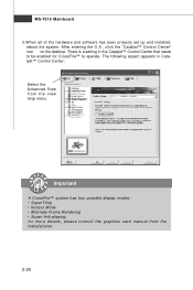
MS-7516 Mainboard 3.W hen all of the hardware and software has been properly set up and installed, reboot the system. Important A CrossFire™ system has four possible ...
MS-7516 Mainboard 3.W hen all of the hardware and software has been properly set up and installed, reboot the system. Important A CrossFire™ system has four possible ...

User Guide
Page 43
... installed properly. BIOS Sign On This will light Red color. BootAttempt This will initialize IDE drive and controller. Then, detect and initialize the video adapter. MS-7516 Mainboard D-LED These four LED groups allow users to 640K and extended memory above 1MB using various patterns. Processor Initialization This will show information regarding...
... installed properly. BIOS Sign On This will light Red color. BootAttempt This will initialize IDE drive and controller. Then, detect and initialize the video adapter. MS-7516 Mainboard D-LED These four LED groups allow users to 640K and extended memory above 1MB using various patterns. Processor Initialization This will show information regarding...

User Guide
Page 45
... to cinch the 6mm clamps over the tubing before inserting the adapter fitting into the turing. 9. Slip the 6mm clamp over the tubing and waterblock 5. MS-7516 Mainboard 3. Attach the tubing to the water block and use pliers to install another adapter, as shown in the figure below . 6.
... to cinch the 6mm clamps over the tubing before inserting the adapter fitting into the turing. 9. Slip the 6mm clamp over the tubing and waterblock 5. MS-7516 Mainboard 3. Attach the tubing to the water block and use pliers to install another adapter, as shown in the figure below . 6.

User Guide
Page 48
MS-7516 Mainboard Entering Setup Power on the screen, press key to enter Setup, restart the system by simultaneously pressing , , and keys. W hen the message below appears ... digit refers to the model number. 6th digit refers to the chipset as I = Intel, N = nVidia, and V = VIA. 7th - 8th digit refers to the customer as MS = all standard customers. You may be slightly different from the latest BIOS and should be held for better system performance. Upon boot-up, the 1st...
MS-7516 Mainboard Entering Setup Power on the screen, press key to enter Setup, restart the system by simultaneously pressing , , and keys. W hen the message below appears ... digit refers to the model number. 6th digit refers to the chipset as I = Intel, N = nVidia, and V = VIA. 7th - 8th digit refers to the customer as MS = all standard customers. You may be slightly different from the latest BIOS and should be held for better system performance. Upon boot-up, the 1st...
User Guide
Page 50
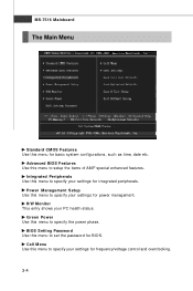
Cell Menu Use this menu to specify your settings for frequency/voltage control and overclocking. 3-4 MS-7516 Mainboard The Main Menu Standard CMOS Features Use this menu to specify the power phase. Integrated Peripherals Use this menu to setup the items of ...
Cell Menu Use this menu to specify your settings for frequency/voltage control and overclocking. 3-4 MS-7516 Mainboard The Main Menu Standard CMOS Features Use this menu to specify the power phase. Integrated Peripherals Use this menu to setup the items of ...


