User Guide
Page 8
...) Statement v Chapter 1. Hardware Setup 2-1 Quick Components Guide 2-2 CPU (Central Processing Unit 2-2 Memory ...2-7 Power Supply ...2-8 Back Panel ...2-11 Connectors ...2-12 Jumper ...2-19 Button ...2-20 Slots ...2-21 LED Status Indicators 2-23 Chapter 3 BIOS Setup 3-1 Entering Setup ...3-2 The Main Menu ...3-4 Standard CMOS Features 3-6 Advanced BIOS Features 3-9 Integrated Peripherals 3-12 Power Management Setup 3-14 PNP...
...) Statement v Chapter 1. Hardware Setup 2-1 Quick Components Guide 2-2 CPU (Central Processing Unit 2-2 Memory ...2-7 Power Supply ...2-8 Back Panel ...2-11 Connectors ...2-12 Jumper ...2-19 Button ...2-20 Slots ...2-21 LED Status Indicators 2-23 Chapter 3 BIOS Setup 3-1 Entering Setup ...3-2 The Main Menu ...3-4 Standard CMOS Features 3-6 Advanced BIOS Features 3-9 Integrated Peripherals 3-12 Power Management Setup 3-14 PNP...
User Guide
Page 24
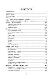
...; mouse/keyboard DIN connector is for a PS/2® mouse/keyboard. 1394 Port (Optional) The IEEE1394 port on the LAN. Yellow Green / Orange LED Color Left Yellow Green Right Orange LED State Condition Off LAN link is selected. You can connect a network cable to IEEE1394 devices. Off 10 Mbit/sec data rate is...
...; mouse/keyboard DIN connector is for a PS/2® mouse/keyboard. 1394 Port (Optional) The IEEE1394 port on the LAN. Yellow Green / Orange LED Color Left Yellow Green Right Orange LED State Condition Off LAN link is selected. You can connect a network cable to IEEE1394 devices. Off 10 Mbit/sec data rate is...
User Guide
Page 30
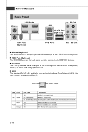
... 2 SPK- 3 SLED 4 BUZ+ 5 PLED 6 BUZ- 7 NC 8 SPK+ DESCRIPTION Ground SpeakerSuspend LED Buzzer+ Power LED BuzzerNo connection Speaker+ 2-16 JFP2 +8 7 Speaker + 21 Power LED JFP1 10 Power Switch + Power LED 2 9 + Reset - HDD 1 +LED JFP1 Pin Definition PIN SIGNAL 1 HD_LED + 2 FP PW R/SLP 3 HD_LED - 4 FP PW ...SLP 5 RST_SW - 6 PW R_SW + 7 RST_SW + 8 PW R_SW - 9 RSVD_DNU DESCRIPTION Hard disk LED pull-up MSG LED pull-up Hard disk active LED MSG LED pull-up Reset Switch low reference pull-down to GND Power Switch high reference pull-up Reset Switch high ...
... 2 SPK- 3 SLED 4 BUZ+ 5 PLED 6 BUZ- 7 NC 8 SPK+ DESCRIPTION Ground SpeakerSuspend LED Buzzer+ Power LED BuzzerNo connection Speaker+ 2-16 JFP2 +8 7 Speaker + 21 Power LED JFP1 10 Power Switch + Power LED 2 9 + Reset - HDD 1 +LED JFP1 Pin Definition PIN SIGNAL 1 HD_LED + 2 FP PW R/SLP 3 HD_LED - 4 FP PW ...SLP 5 RST_SW - 6 PW R_SW + 7 RST_SW + 8 PW R_SW - 9 RSVD_DNU DESCRIPTION Hard disk LED pull-up MSG LED pull-up Hard disk active LED MSG LED pull-up Reset Switch low reference pull-down to GND Power Switch high reference pull-up Reset Switch high ...

User Guide
Page 37
LED12 Lights when PCI_E4 slot is functional. LED15 Lights when PCI_E1 slot is functional. LED Status Indicators Hardware Setup LED11 LED15 LED16 LED12 LED13 LED14 LED3 LED1 LED20 LED10 LED19 LED9 LED18 LED8 LED17 LED7 Name Status LED1 Lights when system is functional. 2-23 LED16 Lights when PCI_E2 slot is power-on standby mode. LED13 Lights when PCI1 slot is on . LED3 Lights when system is functional. LED11 Lights when PCI_E3 slot is functional. LED14 Lights when PCI2 slot is functional.
LED12 Lights when PCI_E4 slot is functional. LED15 Lights when PCI_E1 slot is functional. LED Status Indicators Hardware Setup LED11 LED15 LED16 LED12 LED13 LED14 LED3 LED1 LED20 LED10 LED19 LED9 LED18 LED8 LED17 LED7 Name Status LED1 Lights when system is functional. 2-23 LED16 Lights when PCI_E2 slot is power-on standby mode. LED13 Lights when PCI1 slot is on . LED3 Lights when system is functional. LED11 Lights when PCI_E3 slot is functional. LED14 Lights when PCI2 slot is functional.

User Guide
Page 38
... properly. Group4 Group3 Group2 Group1 BIOS Sign On This will start showing information about logo, processor brand name, etc... The D-LED will hang here if the processor is damaged or not installed properly. Group4 Group3 Group2 Group1 Assign Resources to RAM for fast booting.... Group4 Initializing Floppy Drive Controller Group3 This will set low stack and boot via INT 19h. LED Signal Description Group4 Group3 Group2 Group1 Initializing Video Interface This will start detecting CPU clock, checking type ofvideo onboard. Group4 Group3 ...
... properly. Group4 Group3 Group2 Group1 BIOS Sign On This will start showing information about logo, processor brand name, etc... The D-LED will hang here if the processor is damaged or not installed properly. Group4 Group3 Group2 Group1 Assign Resources to RAM for fast booting.... Group4 Initializing Floppy Drive Controller Group3 This will set low stack and boot via INT 19h. LED Signal Description Group4 Group3 Group2 Group1 Initializing Video Interface This will start detecting CPU clock, checking type ofvideo onboard. Group4 Group3 ...
User Guide
Page 47
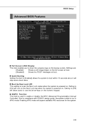
...) on the full screen at boot. [Disabled] Shows the POST messages at boot. Enabling APIC mode will skip some check items. Boot Up Num-Lock LED This setting is to set the Num Lock status when the system is able to compliance with PC2001 design guide, the system is powered on...
...) on the full screen at boot. [Disabled] Shows the POST messages at boot. Enabling APIC mode will skip some check items. Boot Up Num-Lock LED This setting is to set the Num Lock status when the system is able to compliance with PC2001 design guide, the system is powered on...


