
User Guide
Page 4
..., may not cause harmful interference, and (2) this equipment does cause harmful interference to provide reasonable protection against harmful interference in a residential installation. Micro-Star International MS-7345 This device complies with Part 15 of the FCC Rules.
..., may not cause harmful interference, and (2) this equipment does cause harmful interference to provide reasonable protection against harmful interference in a residential installation. Micro-Star International MS-7345 This device complies with Part 15 of the FCC Rules.

User Guide
Page 10
... Base chipset Memory Support - Intel® Core 2 Quad/Core 2 Duo/Pentium /Celeron processors in dex. c om . North Bridge: Intel® P35 chipset - Flexible 8-channel audio with Azalia 1.0 Spec - Meet Microsoft Vista Premium spec - Supports PIO, Bus Master operation mode SATA - m s i.... =c p uf or m ) Supported FSB - 1333/ 1066/ 800 MHz Chipset - Chip integrated by ICH9R En-2 Com pliant with jack sensing - MS-7345 Mainboard Specifications Processor Support - DDR2 800/667 SDRAM (8GB Max) - 4 DDR2 DIMMs (240pin / 1.8V) (For more information on PCB version...
... Base chipset Memory Support - Intel® Core 2 Quad/Core 2 Duo/Pentium /Celeron processors in dex. c om . North Bridge: Intel® P35 chipset - Flexible 8-channel audio with Azalia 1.0 Spec - Meet Microsoft Vista Premium spec - Supports PIO, Bus Master operation mode SATA - m s i.... =c p uf or m ) Supported FSB - 1333/ 1066/ 800 MHz Chipset - Chip integrated by ICH9R En-2 Com pliant with jack sensing - MS-7345 Mainboard Specifications Processor Support - DDR2 800/667 SDRAM (8GB Max) - 4 DDR2 DIMMs (240pin / 1.8V) (For more information on PCB version...

User Guide
Page 14
... (refer to the correct direction marked on the edge of the CPU base. Mainboard photos shown in BIOS. 2. Cover the load plate onto the package. 9. MS-7345 Mainboard CPU & Cooler Installation Procedures for demonstration of the CPU/ cooler installation only. Note that the clip-ends are for Socket 775 1. Push down...
... (refer to the correct direction marked on the edge of the CPU base. Mainboard photos shown in BIOS. 2. Cover the load plate onto the package. 9. MS-7345 Mainboard CPU & Cooler Installation Procedures for demonstration of the CPU/ cooler installation only. Note that the clip-ends are for Socket 775 1. Push down...

User Guide
Page 16
... properly inserted in the DIMM slot. 3. Follow the procedures below to install the m emory module properly. 1. Then push it in until the golden finger on . 2. MS-7345 Mainboard Installing Memory Modules You can barely see the golden finger if the memory module is deeply inserted in the right ori ent at...
... properly inserted in the DIMM slot. 3. Follow the procedures below to install the m emory module properly. 1. Then push it in until the golden finger on . 2. MS-7345 Mainboard Installing Memory Modules You can barely see the golden finger if the memory module is deeply inserted in the right ori ent at...

User Guide
Page 18
... fold the Serial ATA cable into 90-degree angle. TPAGround TPBCablepower Ground 2 10 1 9 IEEE1394 Bracket (Optional) TPA+ Ground TPB+ Cablepower Key (no pin) En-10 MS-7345 Mainboard 7 Serial ATA Connector This connector is compliant with Intel® Front Panel I/O Connectivity Design Guide.
... fold the Serial ATA cable into 90-degree angle. TPAGround TPBCablepower Ground 2 10 1 9 IEEE1394 Bracket (Optional) TPA+ Ground TPB+ Cablepower Key (no pin) En-10 MS-7345 Mainboard 7 Serial ATA Connector This connector is compliant with Intel® Front Panel I/O Connectivity Design Guide.

User Guide
Page 20
... the BIOS utility and clear the record. 1 CINTRU 2 GND En-12 The system will be activated. If the chassis is provided for external audio input. MS-7345 Mainboard 13 Hardware Overclock FSB Jumpers: JB1, JB2 (optional) You can overclock the FSB to the chassis intrusion switch cable. To clear the warning...
... the BIOS utility and clear the record. 1 CINTRU 2 GND En-12 The system will be activated. If the chassis is provided for external audio input. MS-7345 Mainboard 13 Hardware Overclock FSB Jumpers: JB1, JB2 (optional) You can overclock the FSB to the chassis intrusion switch cable. To clear the warning...

User Guide
Page 22
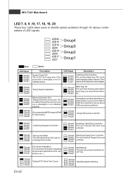
... hang here if the 1 processor is damaged or not installed 3 properly. It allows users to identify system problems through 16 various combinations of LED signals. MS-7345 Mainboard 20 D-Bracket™ 2 Connector This connector is for fast booting. 3 2 Assign Resources to all ISA. 4 1 2 Initializing Keyboard Controller. 1 2 Initializing Hard Drive Controller This...
... hang here if the 1 processor is damaged or not installed 3 properly. It allows users to identify system problems through 16 various combinations of LED signals. MS-7345 Mainboard 20 D-Bracket™ 2 Connector This connector is for fast booting. 3 2 Assign Resources to all ISA. 4 1 2 Initializing Keyboard Controller. 1 2 Initializing Hard Drive Controller This...

User Guide
Page 24
... -12V GND PS-ON GND GND GND -5V 5V 5V 1 11 10 20 3.3V 3.3V GND 5V GND 5V GND PWR OK 5VSB 12V 24 ATX 12V Power Connector (2x2-Pin) This 12V power connector is used to provide power to the CPU. 21 GND GND 12V 12V 43 25... used to provide power to the CPU. +12V 8 5 4 1 GND 26 ATX 12V Power Connector (1x4-Pin) This 12V power connector is used to configure the SLI switch card to connect an ATX 20-pin power supply. En-16 MS-7345 Mainboard 23 ATX 20-Pin Power Connector This connector allows you to SLI or...
... -12V GND PS-ON GND GND GND -5V 5V 5V 1 11 10 20 3.3V 3.3V GND 5V GND 5V GND PWR OK 5VSB 12V 24 ATX 12V Power Connector (2x2-Pin) This 12V power connector is used to provide power to the CPU. 21 GND GND 12V 12V 43 25... used to provide power to the CPU. +12V 8 5 4 1 GND 26 ATX 12V Power Connector (1x4-Pin) This 12V power connector is used to configure the SLI switch card to connect an ATX 20-pin power supply. En-16 MS-7345 Mainboard 23 ATX 20-Pin Power Connector This connector allows you to SLI or...

User Guide
Page 26
... c on nec t or . 1 5 (9-Pin Male Connector) 6 9 D VGA Port The DB15-pin female connector is for monitor. 5 1 15 11 (15-Pin Female DIN Connector) En-18 MS-7345 Mainboard Back Panel A Mouse/Keyboard The standard PS/2® mouse/keyboard DIN connector is provided for a PS/2® mouse/keyboard. PS/2 Mouse connector (Green...
... c on nec t or . 1 5 (9-Pin Male Connector) 6 9 D VGA Port The DB15-pin female connector is for monitor. 5 1 15 11 (15-Pin Female DIN Connector) En-18 MS-7345 Mainboard Back Panel A Mouse/Keyboard The standard PS/2® mouse/keyboard DIN connector is provided for a PS/2® mouse/keyboard. PS/2 Mouse connector (Green...

User Guide
Page 28
..., is used to external speakers through an optical fiber cable. Q External SATA Port This eSATA (External Serial ATA) port is a connector for speakers or headphones. MS-7345 Mainboard H USB Port The USB (Universal Serial Bus) port is used for ex- K MIC (Pink) - M RS-Out (Black) - You can also use the optional...
..., is used to external speakers through an optical fiber cable. Q External SATA Port This eSATA (External Serial ATA) port is a connector for speakers or headphones. MS-7345 Mainboard H USB Port The USB (Universal Serial Bus) port is used for ex- K MIC (Pink) - M RS-Out (Black) - You can also use the optional...
User Guide
Page 30
... not installed properly. Group4 Group3 Group2 Group1 BootAttempt This will initialize IDE drive and controller. Group4 Group3 Group2 Group1 Decompressing BIOS image to the screen. MS-7345 Mainboard LED 7, 8, 9 ,10, 17, 18, 19, 20 These four LEDs allow users to identify system problems through 16 various combinations of LED signals. LED20...
... not installed properly. Group4 Group3 Group2 Group1 BootAttempt This will initialize IDE drive and controller. Group4 Group3 Group2 Group1 Decompressing BIOS image to the screen. MS-7345 Mainboard LED 7, 8, 9 ,10, 17, 18, 19, 20 These four LEDs allow users to identify system problems through 16 various combinations of LED signals. LED20...

User Guide
Page 31
... , and requests you to run the Setup program when: * An error message appears on the BIOS Setup program and allows you to the customer as MS = all standard customers.
... , and requests you to run the Setup program when: * An error message appears on the BIOS Setup program and allows you to the customer as MS = all standard customers.

User Guide
Page 32
... description of the screen. En-24 Sub-Menu If you want to return to use the arrow keys (↑↓ ) to exit the Help screen. MS-7345 Mainboard Entering Setup Power on the screen, press key to field within a sub-menu. If you find a right pointer symbol (as shown in the...
... description of the screen. En-24 Sub-Menu If you want to return to use the arrow keys (↑↓ ) to exit the Help screen. MS-7345 Mainboard Entering Setup Power on the screen, press key to field within a sub-menu. If you find a right pointer symbol (as shown in the...

User Guide
Page 34
.... 2. Important The configuration above are for general use . 1. If you need the detailed settings of BIOS, please see the manual in English version on MSI website. En-26 Save & Exit Setup : Use control keys (↑↓ ) to highlight the Save & Exit Setup field and press , a message... as below appears: Press [Ok] to save the configurations and exit BIOS Setup utility. MS-7345 Mainboard W hen enter the BIOS Setup utility, follow the processes below for general use only. Adjust the Date, Tim e fields. 3. Setup Date/...
.... 2. Important The configuration above are for general use . 1. If you need the detailed settings of BIOS, please see the manual in English version on MSI website. En-26 Save & Exit Setup : Use control keys (↑↓ ) to highlight the Save & Exit Setup field and press , a message... as below appears: Press [Ok] to save the configurations and exit BIOS Setup utility. MS-7345 Mainboard W hen enter the BIOS Setup utility, follow the processes below for general use only. Adjust the Date, Tim e fields. 3. Setup Date/...


