User Guide
Page 3
..., technical guide, BIOS updates, driver updates, and other information: http://www.msi.com.tw/ Contact our technical staff at: support@msi.com.tw iii Windows® 95/98/2000/NT/XP are the properties of their respective owners. Award® is given as to make changes without notice. Visit the MSI website for further guidance. Our products are registered trademarks of International Business...
..., technical guide, BIOS updates, driver updates, and other information: http://www.msi.com.tw/ Contact our technical staff at: support@msi.com.tw iii Windows® 95/98/2000/NT/XP are the properties of their respective owners. Award® is given as to make changes without notice. Visit the MSI website for further guidance. Our products are registered trademarks of International Business...
User Guide
Page 5
... BIOS 2-2 Memory Speed/CPU FSB Support Matrix 2-2 DIMM Module Combination 2-2 Installing DDR Modules 2-3 Back Panel & Power Supply 2-4 Connectors, Jumpers and Slots 2-5 Chapter 3. Getting Started 1-1 Mainboard Specifications 1-2 Mainboard Layout 1-4 MSI Special Features 1-5 Color Management 1-5 D-Bracket™ 2 (Optional 1-6 Core Center 1-8 Core Cell™ Chip 1-10 LiveBIOS™ /Live Driver 1-11 Live Monitor 1-12 Round Cable (Optional 1-13 CPU Thermal Protection 1-13 Chapter 2. BIOS Setup 3-1 The Main Menu 3-2 Standard CMOS Features 3-4 Frequency/Voltage Control...
... BIOS 2-2 Memory Speed/CPU FSB Support Matrix 2-2 DIMM Module Combination 2-2 Installing DDR Modules 2-3 Back Panel & Power Supply 2-4 Connectors, Jumpers and Slots 2-5 Chapter 3. Getting Started 1-1 Mainboard Specifications 1-2 Mainboard Layout 1-4 MSI Special Features 1-5 Color Management 1-5 D-Bracket™ 2 (Optional 1-6 Core Center 1-8 Core Cell™ Chip 1-10 LiveBIOS™ /Live Driver 1-11 Live Monitor 1-12 Round Cable (Optional 1-13 CPU Thermal Protection 1-13 Chapter 2. BIOS Setup 3-1 The Main Menu 3-2 Standard CMOS Features 3-4 Frequency/Voltage Control...
User Guide
Page 8
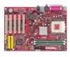
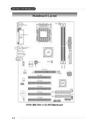
MS-7021 ATX Mainboard Mainboard Specifications CPU † Supports Socket A (Socket-462) for AMD® Athlon™ /Athlon™ XP /Duron™ processors † Supports Athlon XP 1500+ to 2GB DDR200/266/333/400 SDRAMs † Supports 2.5v DDR SDRAM Slots † One AGP (Accelerated Graphics Port) 1.5V slot † Five 32-bit PCI bus slots (support 3.3v/5v PCI bus interface) On-Board IDE † An IDE controller on the VT8237 chipset provides IDE HDD/CD-ROM with PIO, Bus Master and Ultra DMA66...
MS-7021 ATX Mainboard Mainboard Specifications CPU † Supports Socket A (Socket-462) for AMD® Athlon™ /Athlon™ XP /Duron™ processors † Supports Athlon XP 1500+ to 2GB DDR200/266/333/400 SDRAMs † Supports 2.5v DDR SDRAM Slots † One AGP (Accelerated Graphics Port) 1.5V slot † Five 32-bit PCI bus slots (support 3.3v/5v PCI bus interface) On-Board IDE † An IDE controller on the VT8237 chipset provides IDE HDD/CD-ROM with PIO, Bus Master and Ultra DMA66...
User Guide
Page 10
MS-7021 ATX Mainboard Mainboard Layout Top : mouse Bottom: keyboard SOCKET 462 CFAN1 Top : Parallel Port Bottom: COM A ATX Power Supply Top: Coaxial SPDIF Out Bottom: USB ports Top: LAN jack Bottom: USB ports VIA KT600 T:Line-In M: Line-Out B:Mic JCD1 Winbond W83697HF J6 JPW1 NBFAN1 AGP Slot Realtek 8201BL PCI Slot 1 DDR 1 DDR 2 FDD 1 SATA1 SATA2 Codec JAUD1 BATT + JBAT1 PCI Slot 2 PCI Slot 3 PCI Slot 4 PCI Slot 5 VIA VT8237 IDE 1 IDE 2 JUSB2 JUSB1 SFAN1 JLED1 JFP1 JFP2 KT6V (MS-7021 v1.X) ATX Mainboard 1-4
MS-7021 ATX Mainboard Mainboard Layout Top : mouse Bottom: keyboard SOCKET 462 CFAN1 Top : Parallel Port Bottom: COM A ATX Power Supply Top: Coaxial SPDIF Out Bottom: USB ports Top: LAN jack Bottom: USB ports VIA KT600 T:Line-In M: Line-Out B:Mic JCD1 Winbond W83697HF J6 JPW1 NBFAN1 AGP Slot Realtek 8201BL PCI Slot 1 DDR 1 DDR 2 FDD 1 SATA1 SATA2 Codec JAUD1 BATT + JBAT1 PCI Slot 2 PCI Slot 3 PCI Slot 4 PCI Slot 5 VIA VT8237 IDE 1 IDE 2 JUSB2 JUSB1 SFAN1 JLED1 JFP1 JFP2 KT6V (MS-7021 v1.X) ATX Mainboard 1-4
User Guide
Page 12
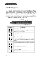
... other failures. Initializing Keyboard Controller. The 4 LEDs can use graphic signal display to help users understand their system. D-Bracket™ 2 1 2 3 4 D-Bracket 2 Description System Power ON 1 2 - Decompressing BIOS image to the screen. 1-6 The D-LED will start writing VGA sign-on message to RAM for the overclocking users. This special feature is an external USB bracket integrating four Diagnostic LEDs, which use the feature to debug the system. D-Bracket™ 2 supports both USB 1.1 & 2.0 spec. Testing onboard memory size. MS-7021 ATX Mainboard...
... other failures. Initializing Keyboard Controller. The 4 LEDs can use graphic signal display to help users understand their system. D-Bracket™ 2 1 2 3 4 D-Bracket 2 Description System Power ON 1 2 - Decompressing BIOS image to the screen. 1-6 The D-LED will start writing VGA sign-on message to RAM for the overclocking users. This special feature is an external USB bracket integrating four Diagnostic LEDs, which use the feature to debug the system. D-Bracket™ 2 supports both USB 1.1 & 2.0 spec. Testing onboard memory size. MS-7021 ATX Mainboard...
User Guide
Page 14
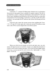
... for users to overclock, overspec or to adjust the thresholds of system to choose the "Auto mode" or "User mode" of overclocking, CoreCenter is advanced combination of the popular PC Alert and Fuzzy Logic. MS-7021 ATX Mainboard CoreCenter CoreCenter - (TM) contains OC Menu panel, wherein users can detect, view and adjust the PC hardware and system status during real time operation. This all fans speeds.
... for users to overclock, overspec or to adjust the thresholds of system to choose the "Auto mode" or "User mode" of overclocking, CoreCenter is advanced combination of the popular PC Alert and Fuzzy Logic. MS-7021 ATX Mainboard CoreCenter CoreCenter - (TM) contains OC Menu panel, wherein users can detect, view and adjust the PC hardware and system status during real time operation. This all fans speeds.
User Guide
Page 17
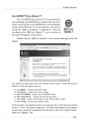
... "MSI Live Update 3" icon, and the following screen will appear on the update instructions, insert the companion CD and refer to the "Live Update Guide" under the "Manual" Tab. 1-11 Updates the BIOS online. ö Live Driver - Click the desired button to install the "MSI Live Update 3" application. Getting Started Live BIOS™ /Live Driver™ The Live BIOS™ /Live Driver™ is a tool used to detect and update your BIOS/drivers online...
... "MSI Live Update 3" icon, and the following screen will appear on the update instructions, insert the companion CD and refer to the "Live Update Guide" under the "Manual" Tab. 1-11 Updates the BIOS online. ö Live Driver - Click the desired button to install the "MSI Live Update 3" application. Getting Started Live BIOS™ /Live Driver™ The Live BIOS™ /Live Driver™ is a tool used to detect and update your BIOS/drivers online...
User Guide
Page 18
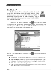
... the functions listed below: l Auto Search - Exits the Live Monitor™ application. MS-7021 ATX Mainboard Live Monitor™ The Live Monitor™ is any. To use the function, you need immediately. You can specify how often the system will appear. l FAQ - l Preference - Provides a link to a database which contains various possible questions about MSI's products for users to install the "MSI Live Update 3" application. l View...
... the functions listed below: l Auto Search - Exits the Live Monitor™ application. MS-7021 ATX Mainboard Live Monitor™ The Live Monitor™ is any. To use the function, you need immediately. You can specify how often the system will appear. l FAQ - l Preference - Provides a link to a database which contains various possible questions about MSI's products for users to install the "MSI Live Update 3" application. l View...
User Guide
Page 21
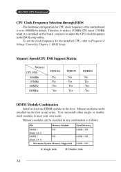
... DIMM Module Combination Install at 133MHz when it is set the clock frequency for CPU clock frequency of the motherboard is installed on the slots. Therefore, to make a 133MHz CPU run at least one DIMM module on the board, you have to adjust the CPU clock frequency in the BIOS setup utility. To set to 100MHz by default. BIOS Setup. Memory modules can install either single- MS-7021 ATX Mainboard CPU Clock Frequency Selection through BIOS The hardware configuration for the installed CPU, refer to...
... DIMM Module Combination Install at 133MHz when it is set the clock frequency for CPU clock frequency of the motherboard is installed on the slots. Therefore, to make a 133MHz CPU run at least one DIMM module on the board, you have to adjust the CPU clock frequency in the BIOS setup utility. To set to 100MHz by default. BIOS Setup. Memory modules can install either single- MS-7021 ATX Mainboard CPU Clock Frequency Selection through BIOS The hardware configuration for the installed CPU, refer to...
User Guide
Page 25
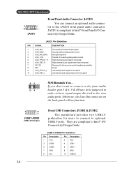
... spec) Front USB Connectors: JUSB1 & JUSB2 The mainboard provides two USB2.0 pinheaders for future use to control headphone amplifier 8 KEY No pin 9 AUD_FPOUT_L Left channel audio signal to Intel® I /O Connectivity Design Guide. JAUD1 Pin Definition PIN SIGNAL DESCRIPTION 1 AUD_MIC Front panel microphone input signal 2 AUD_GND Ground used by analog audio circuits 3 AUD_MIC_BIAS Microphone power 4 AUD_VCC Filtered +5V used by analog audio circuits 5 AUD_FPOUT_R Right channel audiosignal to front panel 6 AUD_RET_R Right channel audio...
... spec) Front USB Connectors: JUSB1 & JUSB2 The mainboard provides two USB2.0 pinheaders for future use to control headphone amplifier 8 KEY No pin 9 AUD_FPOUT_L Left channel audio signal to Intel® I /O Connectivity Design Guide. JAUD1 Pin Definition PIN SIGNAL DESCRIPTION 1 AUD_MIC Front panel microphone input signal 2 AUD_GND Ground used by analog audio circuits 3 AUD_MIC_BIAS Microphone power 4 AUD_VCC Filtered +5V used by analog audio circuits 5 AUD_FPOUT_R Right channel audiosignal to front panel 6 AUD_RET_R Right channel audio...
User Guide
Page 27
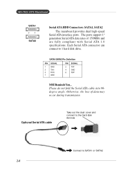
.... Optional Serial ATA cable Take out the dust cover and connect to the hard disk d evi c es Connect to 1 hard disk drive. The ports support 1st generation Serial ATA data rates of data may occur during transmission. Otherwise, the loss of 150MB/s and are fully compliant with Serial ATA 1.0 specifications. Each Serial ATA connector can connect to SATA1 or SATA2 2-8 MS-7021 ATX Mainboard SATA1 7 1 SATA2 Serial ATA HDD Connectors: SATA1, SATA2 The mainboard provides dual high-speed Serial ATA...
.... Optional Serial ATA cable Take out the dust cover and connect to the hard disk d evi c es Connect to 1 hard disk drive. The ports support 1st generation Serial ATA data rates of data may occur during transmission. Otherwise, the loss of 150MB/s and are fully compliant with Serial ATA 1.0 specifications. Each Serial ATA connector can connect to SATA1 or SATA2 2-8 MS-7021 ATX Mainboard SATA1 7 1 SATA2 Serial ATA HDD Connectors: SATA1, SATA2 The mainboard provides dual high-speed Serial ATA...
User Guide
Page 29
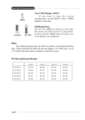
... result in a failure to 1-2 pin position. PCI Interrupt Request Routing PCI Slot 1 PCI Slot 2 PCI Slot 3 PCI Slot 4 PCI Slot 5 Order 1 INT A# INT B# INT C# INT D# INT B# Order 2 INT B# INT C# INT D# INT A# INT C# Order 3 INT C# INT D# INT A# INT B# INT D# Order 4 INT D# INT A# INT B# INT C# INT A# 2-10 Avoid clearing the CMOS while the system is off. You can clear CMOS by shorting 2-3 pin while the system is on; MS-7021 ATX Mainboard 1 3 JBAT1 Clear CMOS Jumper: JBAT1 If...
... result in a failure to 1-2 pin position. PCI Interrupt Request Routing PCI Slot 1 PCI Slot 2 PCI Slot 3 PCI Slot 4 PCI Slot 5 Order 1 INT A# INT B# INT C# INT D# INT B# Order 2 INT B# INT C# INT D# INT A# INT C# Order 3 INT C# INT D# INT A# INT B# INT D# Order 4 INT D# INT A# INT B# INT C# INT A# 2-10 Avoid clearing the CMOS while the system is off. You can clear CMOS by shorting 2-3 pin while the system is on; MS-7021 ATX Mainboard 1 3 JBAT1 Clear CMOS Jumper: JBAT1 If...
User Guide
Page 31
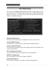
.... MS-7021 ATX Mainboard The Main Menu Once you enter AMIBIOS NEW SETUP UTILITY, the Main Menu will appear on the screen. Standard CMOS Features Use this menu for integrated peripherals. 3-2 PNP/PCI Configurations This entry appears if your settings for basic system configurations, such as time, date etc. Integrated Peripherals Use this menu to setup the items of AMI® special enhanced features. Power Management Features Use this menu to change the values in the chipset...
.... MS-7021 ATX Mainboard The Main Menu Once you enter AMIBIOS NEW SETUP UTILITY, the Main Menu will appear on the screen. Standard CMOS Features Use this menu for integrated peripherals. 3-2 PNP/PCI Configurations This entry appears if your settings for basic system configurations, such as time, date etc. Integrated Peripherals Use this menu to setup the items of AMI® special enhanced features. Power Management Features Use this menu to change the values in the chipset...
User Guide
Page 35
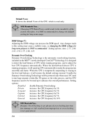
... data like 3D games or the video process, and the CPU frequency need to be powered only when users' PC need to run smoothly and faster. MS-7021 ATX Mainboard Default Vcore It shows the default Vcore of the CPU, which is not guaranteed. 3-6 MSI Reminds You... Changing CPU Ratio/Vcore could result in the MSITM's newly developed CoreCellTMTechnology. Setting options: Auto, 2.55, 2.60, 2.65, 2.70, 2.75, 2.80...
... data like 3D games or the video process, and the CPU frequency need to be powered only when users' PC need to run smoothly and faster. MS-7021 ATX Mainboard Default Vcore It shows the default Vcore of the CPU, which is not guaranteed. 3-6 MSI Reminds You... Changing CPU Ratio/Vcore could result in the MSITM's newly developed CoreCellTMTechnology. Setting options: Auto, 2.55, 2.60, 2.65, 2.70, 2.75, 2.80...
User Guide
Page 39
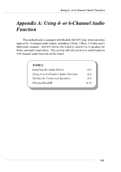
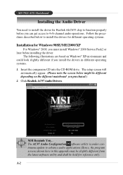
The section will tell you how to attach 4 or 6 speakers for 6-channel audio output, including 2 Front, 2 Rear, 1 Center and 1 Subwoofer channel. TOPICS Installing the Audio Driver A-2 Using 4-or 6-Channel Audio Function A-4 Testing the Connected Speakers A-9 Playing KaraOK A-11 A-1 Using 4- or 6-Channel Audio Function The motherboard is equipped with Realtek ALC655 chip, which provides support for better surround sound effect. or 6-Channel Audio Function Appendix A: Using 4- ALC655 allows the board to install and use 4-/6-channel audio function on the board.
The section will tell you how to attach 4 or 6 speakers for 6-channel audio output, including 2 Front, 2 Rear, 1 Center and 1 Subwoofer channel. TOPICS Installing the Audio Driver A-2 Using 4-or 6-Channel Audio Function A-4 Testing the Connected Speakers A-9 Playing KaraOK A-11 A-1 Using 4- or 6-Channel Audio Function The motherboard is equipped with Realtek ALC655 chip, which provides support for better surround sound effect. or 6-Channel Audio Function Appendix A: Using 4- ALC655 allows the board to install and use 4-/6-channel audio function on the board.
User Guide
Page 40
... software utility and shall be different depending on the different mainboard you can get access to 4-/6-channel audio operations. The AC97 Audio Configuration software utility is under continuous update to install the drivers for different operating systems. Installation for reference only. MS-7021 ATX Mainboard Installing the Audio Driver You need to install the driver for Realtek ALC655 chip to function properly before installing the driver. Hence, the program screens shown here in different operating systems. 1. The setup screen...
... software utility and shall be different depending on the different mainboard you can get access to 4-/6-channel audio operations. The AC97 Audio Configuration software utility is under continuous update to install the drivers for different operating systems. Installation for reference only. MS-7021 ATX Mainboard Installing the Audio Driver You need to install the driver for Realtek ALC655 chip to function properly before installing the driver. Hence, the program screens shown here in different operating systems. 1. The setup screen...
User Guide
Page 42
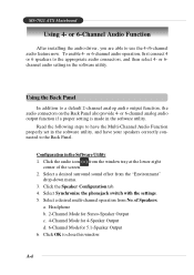
... this window. Headphone b. 2-Channel Mode for Stereo-Speaker Output c. 4-Channel Mode for 4-Speaker Output d. 6-Channel Mode for 5.1-Speaker Output 6. Read the following steps to the Back Panel. or 6channel audio setting in the software utility. or 6-channel analog audio output function if a proper setting is made in the software utility. Click the Speaker Configuration tab. 4. MS-7021 ATX Mainboard Using 4- To enable 4- Click the audio icon from the window tray at the lower-right corner of Speakers. Click OK to a default 2-channel analog audio...
... this window. Headphone b. 2-Channel Mode for Stereo-Speaker Output c. 4-Channel Mode for 4-Speaker Output d. 6-Channel Mode for 5.1-Speaker Output 6. Read the following steps to the Back Panel. or 6channel audio setting in the software utility. or 6-channel analog audio output function if a proper setting is made in the software utility. Click the Speaker Configuration tab. 4. MS-7021 ATX Mainboard Using 4- To enable 4- Click the audio icon from the window tray at the lower-right corner of Speakers. Click OK to a default 2-channel analog audio...
User Guide
Page 50
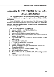
... Serial ATA RAID Introduction Appendix. SATA hard drives deliver blistering transfer speeds of VT8237 SATA RAID are: 1. Supports RAID 0 and RAID 1. 7. 4 KB to connect your drive and improving the airflow inside your PC. Using 4- Serial ATA uses long, thin cables, making it easier to 64 KB striping block size support. 8. Event log for support of up to two Serial ATA (Serial ATA RAID) drives. Only SATA supports RAID. 3. Supports Ultra DMA mode 6/5/4/3/2/1/0, DMA mode 2/1/0, and PIO mode 4/3/2/1/0. 6. Windows-based RAID configure and management software tool. (Compatible with BIOS...
... Serial ATA RAID Introduction Appendix. SATA hard drives deliver blistering transfer speeds of VT8237 SATA RAID are: 1. Supports RAID 0 and RAID 1. 7. 4 KB to connect your drive and improving the airflow inside your PC. Using 4- Serial ATA uses long, thin cables, making it easier to 64 KB striping block size support. 8. Event log for support of up to two Serial ATA (Serial ATA RAID) drives. Only SATA supports RAID. 3. Supports Ultra DMA mode 6/5/4/3/2/1/0, DMA mode 2/1/0, and PIO mode 4/3/2/1/0. 6. Windows-based RAID configure and management software tool. (Compatible with BIOS...
User Guide
Page 51
... users wishing to install their VIA SATA RAID driver and RAID software, proceed to the operating system. This can be found on VIA SATA RAID Host Controller. The different methods are called "members". The advantage of combining two or more hard disk drives into one drives fails, a mirrored copy of Drives Capacity Benefits RAID 0 2 Number drives * 2 Highest performance without data (Striping) protection RAID 1 2 Smallest size Data protection (Mirroring) B-2 Different RAID...
... users wishing to install their VIA SATA RAID driver and RAID software, proceed to the operating system. This can be found on VIA SATA RAID Host Controller. The different methods are called "members". The advantage of combining two or more hard disk drives into one drives fails, a mirrored copy of Drives Capacity Benefits RAID 0 2 Number drives * 2 Highest performance without data (Striping) protection RAID 1 2 Smallest size Data protection (Mirroring) B-2 Different RAID...
User Guide
Page 63
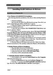
... IDE RAID Host Controller should appear. Start the installation: Boot from My Computer followed by the System icon. 2. Insert the MSI CD into drive A: and press . 4. Under the Driver tab, click on Windows XP Setup screen, press the key. 5. B-14 Depending on your operation system, choose VIA Serial ATA RAID Controller(Windows XP), VIA Serial ATA RAID Controller(Windows 2000) or VIA Serial ATA RAID Controller(Windows NT4) from the list that appears on VIA SATA RAID Utility. 4. The drivers...
... IDE RAID Host Controller should appear. Start the installation: Boot from My Computer followed by the System icon. 2. Insert the MSI CD into drive A: and press . 4. Under the Driver tab, click on Windows XP Setup screen, press the key. 5. B-14 Depending on your operation system, choose VIA Serial ATA RAID Controller(Windows XP), VIA Serial ATA RAID Controller(Windows 2000) or VIA Serial ATA RAID Controller(Windows NT4) from the list that appears on VIA SATA RAID Utility. 4. The drivers...


