
User Guide
Page 2
Operation of this equipment in a residential area is subject to the following two conditions: (1) this device may not cause harmful interference, and (2) this device must accept any , must be used in which case the user will be required to correct the interference at his own expense. Operation is likely to cause harmful interference, in accordance with the instruction manual, may cause undesired operation ii These limits are designed to operate the equipment. Notice 2 Shielded interface cables and A.C. Micro-Star International MS-6712 This device complies with Part 15 of the ...
Operation of this equipment in a residential area is subject to the following two conditions: (1) this device may not cause harmful interference, and (2) this device must accept any , must be used in which case the user will be required to correct the interference at his own expense. Operation is likely to cause harmful interference, in accordance with the instruction manual, may cause undesired operation ii These limits are designed to operate the equipment. Notice 2 Shielded interface cables and A.C. Micro-Star International MS-6712 This device complies with Part 15 of the ...

User Guide
Page 3
Trademarks All trademarks are registered trademarks of AMD Corporation. AMD, Athlon™, Athlon™ XP, Thoroughbred™, and Duron™ are the properties of their respective owners. Microsoft is a registered trademark of American Megatrends Inc. Kensington and MicroSaver are under continual improvement and we reserve the right to the correctness of its contents. for KT4AV Series Date May 2004 iii We take every care in this document, but no guarantee is given as to make changes without notice. Our products are registered trademarks of the Kensington Technology Group....
Trademarks All trademarks are registered trademarks of AMD Corporation. AMD, Athlon™, Athlon™ XP, Thoroughbred™, and Duron™ are the properties of their respective owners. Microsoft is a registered trademark of American Megatrends Inc. Kensington and MicroSaver are under continual improvement and we reserve the right to the correctness of its contents. for KT4AV Series Date May 2004 iii We take every care in this document, but no guarantee is given as to make changes without notice. Our products are registered trademarks of the Kensington Technology Group....
User Guide
Page 4
Keep this User's Manual for FAQ, technical guide, BIOS updates, driver updates, and other information: http://www.msi.com.tw/ Contact our technical staff at: support@msi.com.tw Safety Instructions 1. Lay this equipment away from the user's manual, please contact your place of breakage. 1 2 . All...been exposed to User's Manual. Make sure the voltage of the power source and adjust properly 110/220V before setting it . Visit the MSI website for future reference. 3. Alternatively, please try the following situations arises, get it work well or you can not step on card ...
Keep this User's Manual for FAQ, technical guide, BIOS updates, driver updates, and other information: http://www.msi.com.tw/ Contact our technical staff at: support@msi.com.tw Safety Instructions 1. Lay this equipment away from the user's manual, please contact your place of breakage. 1 2 . All...been exposed to User's Manual. Make sure the voltage of the power source and adjust properly 110/220V before setting it . Visit the MSI website for future reference. 3. Alternatively, please try the following situations arises, get it work well or you can not step on card ...
User Guide
Page 5
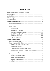
Getting Started 1-1 Mainboard Specifications 1-2 Mainboard Layout 1-4 MSI Special Features 1-5 Live Monitor 1-5 D-Bracket™ 2 (Optional 1-6 MSI DVD 5.1 Channel (Optional 1-8 LiveBIOS™/Live Driver 1-10 CPU Thermal Protection 1-11 S-Bracket (Optional 1-11 Chapter 2. Hardware Setup 2-1 Quick Components Guide 2-2 Central Processing Unit: CPU 2-3 ...
Getting Started 1-1 Mainboard Specifications 1-2 Mainboard Layout 1-4 MSI Special Features 1-5 Live Monitor 1-5 D-Bracket™ 2 (Optional 1-6 MSI DVD 5.1 Channel (Optional 1-8 LiveBIOS™/Live Driver 1-10 CPU Thermal Protection 1-11 S-Bracket (Optional 1-11 Chapter 2. Hardware Setup 2-1 Quick Components Guide 2-2 Central Processing Unit: CPU 2-3 ...

User Guide
Page 6
BIOS Setup 3-1 Entering Setup 3-2 vi ATX 20-Pin Power Connector: JWR1 2-9 Back Panel 2-10 Mouse Connector 2-10 Keyboard Connector 2-11 USB Connectors 2-11 Parallel Port Connector: LPT1 2-12 Audio Port Connectors 2-...
BIOS Setup 3-1 Entering Setup 3-2 vi ATX 20-Pin Power Connector: JWR1 2-9 Back Panel 2-10 Mouse Connector 2-10 Keyboard Connector 2-11 USB Connectors 2-11 Parallel Port Connector: LPT1 2-12 Audio Port Connectors 2-...
User Guide
Page 7
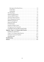
Selecting the First Boot Device 3-2 Control Keys 3-3 Getting Help 3-3 The Main Menu 3-4 Standard CMOS Features 3-6 Advanced BIOS Features 3-8 Advanced Chipset Features 3-13 Power Management Features 3-18 PNP/PCI Configurations 3-22 Integrated Peripherals 3-24 PC Health Status 3-27 Frequency/Voltage Control 3-28 Set Supervisor/User Password 3-30 Load High Performance/BIOS Setup Defaults 3-31 Appendix: Using 4- or 6-Channel Audio Function A-4 Testing the Connected Speakers A-14 Playing KaraOK A-16 Troubleshooting T-1 Glossary G-1 vii or 6-Channel Audio Function A-1 ...
Selecting the First Boot Device 3-2 Control Keys 3-3 Getting Help 3-3 The Main Menu 3-4 Standard CMOS Features 3-6 Advanced BIOS Features 3-8 Advanced Chipset Features 3-13 Power Management Features 3-18 PNP/PCI Configurations 3-22 Integrated Peripherals 3-24 PC Health Status 3-27 Frequency/Voltage Control 3-28 Set Supervisor/User Password 3-30 Load High Performance/BIOS Setup Defaults 3-31 Appendix: Using 4- or 6-Channel Audio Function A-4 Testing the Connected Speakers A-14 Playing KaraOK A-16 Troubleshooting T-1 Glossary G-1 vii or 6-Channel Audio Function A-1 ...

User Guide
Page 8
The MS-6712 v1.X ATX mainboard is based on VIA® Apollo KT400A North Bridge & VT8235 South Bridge chipset for purchasing the MS-6712 v1.X ATX mainboard. Designed to fit the advanced AMD® Athlon™, Athlon™ XP or Duron™ processors, the MS-6712 delivers a high performance and professional desktop platform solution. 1-1 Getting Started Getting Started Thank you for optimal system efficiency.
The MS-6712 v1.X ATX mainboard is based on VIA® Apollo KT400A North Bridge & VT8235 South Bridge chipset for purchasing the MS-6712 v1.X ATX mainboard. Designed to fit the advanced AMD® Athlon™, Athlon™ XP or Duron™ processors, the MS-6712 delivers a high performance and professional desktop platform solution. 1-1 Getting Started Getting Started Thank you for optimal system efficiency.
User Guide
Page 9
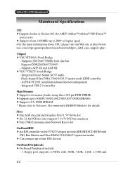
msi.com.tw/program/products/mainboard/mbd/pro_mbd_cpu_support.php) Chipset † VIA® KT400A North Bridge - Integrated Direct Sound AC97 audio - Supports 200/266/333MHz front ... - Supports AGP 4X and AGP 8X † VIA® VT8235 South Bridge - ACPI & PC2001 compliant enhanced power management - Supports DDR200/266/333/400* - MS-6712 ATX Mainboard Mainboard Specifications CPU † Supports Socket A (Socket-462) for details. Slots † One AGP (Accelerated Graphics Port) 1.5V 8x/4x slot † Six 32...
msi.com.tw/program/products/mainboard/mbd/pro_mbd_cpu_support.php) Chipset † VIA® KT400A North Bridge - Integrated Direct Sound AC97 audio - Supports 200/266/333MHz front ... - Supports AGP 4X and AGP 8X † VIA® VT8235 South Bridge - ACPI & PC2001 compliant enhanced power management - Supports DDR200/266/333/400* - MS-6712 ATX Mainboard Mainboard Specifications CPU † Supports Socket A (Socket-462) for details. Slots † One AGP (Accelerated Graphics Port) 1.5V 8x/4x slot † Six 32...

User Guide
Page 10
Dimension †ATX Form Factor: 30.5 cm (L) x 21 cm (W) Mounting † 6 mounting holes Others † Suspend to RAM/Disk (S3/S4) †PC2001 compliant † Support WOL/WOR 1-3 ...
Dimension †ATX Form Factor: 30.5 cm (L) x 21 cm (W) Mounting † 6 mounting holes Others † Suspend to RAM/Disk (S3/S4) †PC2001 compliant † Support WOL/WOR 1-3 ...

User Guide
Page 12
... Search - z View Last Result - Allows you to run the application. Exits the Live Monitor™ application. z Preference - Getting Started MSI Special Features Live Monitor™ The Live Monitor™ is any. You can specify how often the system will automatically search for users to ... the search for the BIOS/drivers version you need immediately. Configures the Search function, including the Search schedule. After the installation, the "MSI Live Monitor" icon (as shown on the right) will appear. To use the function, you need to inquire. 1-5 Searches for the...
... Search - z View Last Result - Allows you to run the application. Exits the Live Monitor™ application. z Preference - Getting Started MSI Special Features Live Monitor™ The Live Monitor™ is any. You can specify how often the system will automatically search for users to ... the search for the BIOS/drivers version you need immediately. Configures the Search function, including the Search schedule. After the installation, the "MSI Live Monitor" icon (as shown on the right) will appear. To use the function, you need to inquire. 1-5 Searches for the...

User Guide
Page 13
... will start writing VGA sign-on message to debug the system. Decompressing BIOS image to detect if there are any problems or failures. MS-6712 ATX Mainboard D-Bracket™ 2 (Optional) D-Bracket™ 2 is damaged or not installed properly.
... will start writing VGA sign-on message to debug the system. Decompressing BIOS image to detect if there are any problems or failures. MS-6712 ATX Mainboard D-Bracket™ 2 (Optional) D-Bracket™ 2 is damaged or not installed properly.

User Guide
Page 14
Getting Started Red Green D-Bracket™ 2 Description Processor Initialization - This will initialize IDE drive and controller. Then, detect and initialize the video adapter. This will show information regarding the processor (like brand name, system bus, etc...) Testing RTC (Real Time Clock) Initializing Video Interface - Initializing Hard Drive Controller - Operating System Booting 1-7 BIOS Sign On - This will initializing Floppy Drive and controller. Testing Base and Extended Memory - This will set low stack and boot via INT 19h. Testing base ...
Getting Started Red Green D-Bracket™ 2 Description Processor Initialization - This will initialize IDE drive and controller. Then, detect and initialize the video adapter. This will show information regarding the processor (like brand name, system bus, etc...) Testing RTC (Real Time Clock) Initializing Video Interface - Initializing Hard Drive Controller - Operating System Booting 1-7 BIOS Sign On - This will initializing Floppy Drive and controller. Testing Base and Extended Memory - This will set low stack and boot via INT 19h. Testing base ...

User Guide
Page 15
... format first. 1-8 Select 6 speaker mode (5.1 channel). Using 4or 6-Channel Audio Function. MS-6712 ATX Mainboard MSI DVD 5.1 Channel (Optional) The motherboard comes with 6-channel audio output, you should convert it to enable 6-channel support with MSI DVD: 1. To play DVD with MSI DVD application which supports 5.1 channel (6-channel audio) operation. Click on how to select...
... format first. 1-8 Select 6 speaker mode (5.1 channel). Using 4or 6-Channel Audio Function. MS-6712 ATX Mainboard MSI DVD 5.1 Channel (Optional) The motherboard comes with 6-channel audio output, you should convert it to enable 6-channel support with MSI DVD: 1. To play DVD with MSI DVD application which supports 5.1 channel (6-channel audio) operation. Click on how to select...

User Guide
Page 16
Click on the icon at the bottom-right corner of the control panel. 2. Click OK. To enter the online help coming with the application. Getting Started 4. For more information about MSI DVD, you can refer to the online help : 1. The following window appears. Click here 3. Click MSIDVD FAQ. 1-9
Click on the icon at the bottom-right corner of the control panel. 2. Click OK. To enter the online help coming with the application. Getting Started 4. For more information about MSI DVD, you can refer to the online help : 1. The following window appears. Click here 3. Click MSIDVD FAQ. 1-9
User Guide
Page 17
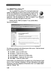
Updates the drivers online. z Live VGA Driver - Updates the utilities online. MS-6712 ATX Mainboard Live BIOS™/Live Driver™ The Live BIOS™/Live Driver™ is displayed. z Live VGA BIOS - To use the function, you purchased ... for the correct BIOS/driver version throughout the Web site. z Live Driver - Updates the VGA driver online. Updates the BIOS online. After the installation, the "MSI Live Update 2" icon (as shown on the right) will appear: Five buttons are placed on the leftmost pane of the functions listed above, a "sorry" message...
Updates the drivers online. z Live VGA Driver - Updates the utilities online. MS-6712 ATX Mainboard Live BIOS™/Live Driver™ The Live BIOS™/Live Driver™ is displayed. z Live VGA BIOS - To use the function, you purchased ... for the correct BIOS/driver version throughout the Web site. z Live Driver - Updates the VGA driver online. Updates the BIOS online. After the installation, the "MSI Live Update 2" icon (as shown on the right) will appear: Five buttons are placed on the leftmost pane of the functions listed above, a "sorry" message...

User Guide
Page 18
... meet your system will then drop down and resume normal. This CPU Thermal Protection mechanism works on S-Bracket, refer to prevent the CPU from overheating, MSI has developed a CPU Thermal Protection mechanism for AMD Athlon™ XP CPU only. With the S-Bracket, your own need. For more information on a thermal signal...
... meet your system will then drop down and resume normal. This CPU Thermal Protection mechanism works on S-Bracket, refer to prevent the CPU from overheating, MSI has developed a CPU Thermal Protection mechanism for AMD Athlon™ XP CPU only. With the S-Bracket, your own need. For more information on a thermal signal...

User Guide
Page 19
Also, it provides the instructions on connecting the peripheral devices, such as how to install the CPU, memory modules, and expansion cards, as well as the mouse, keyboard, etc. Hardware Setup Hardware Setup This chapter tells you how to setup the jumpers on the mainboard. While doing the installation, be careful in holding the components and follow the installation procedures. 2-1
Also, it provides the instructions on connecting the peripheral devices, such as how to install the CPU, memory modules, and expansion cards, as well as the mouse, keyboard, etc. Hardware Setup Hardware Setup This chapter tells you how to setup the jumpers on the mainboard. While doing the installation, be careful in holding the components and follow the installation procedures. 2-1

User Guide
Page 21
The mainboard uses a CPU socket called Socket A for reference. 2-3 If you are installing the CPU, make sure that the CPU and heatsink are needed to prevent overheating. Then, make sure the CPU has a heat sink and a cooling fan attached on the top to prevent damaging the processor and ensuring reliable operation. When you do not find the heat sink and cooling fan, contact your dealer to get more information on the computer. CPU Core Speed Derivation Procedure If CPU Clock = Core/Bus ratio = then CPU core speed = = = 100MHz 14 Host Clock x Core/Bus ratio 100MHz x 14 1.4 ...
The mainboard uses a CPU socket called Socket A for reference. 2-3 If you are installing the CPU, make sure that the CPU and heatsink are needed to prevent overheating. Then, make sure the CPU has a heat sink and a cooling fan attached on the top to prevent damaging the processor and ensuring reliable operation. When you do not find the heat sink and cooling fan, contact your dealer to get more information on the computer. CPU Core Speed Derivation Procedure If CPU Clock = Core/Bus ratio = then CPU core speed = = = 100MHz 14 Host Clock x Core/Bus ratio 100MHz x 14 1.4 ...

User Guide
Page 22
... raise the lever up to your fingers pressing tightly on top of the correct installation procedures may cause permanent damages to a 90degree angle. 3. MS-6712 ATX Mainboard CPU Installation Procedures for the gold arrow.
... raise the lever up to your fingers pressing tightly on top of the correct installation procedures may cause permanent damages to a 90degree angle. 3. MS-6712 ATX Mainboard CPU Installation Procedures for the gold arrow.
User Guide
Page 23
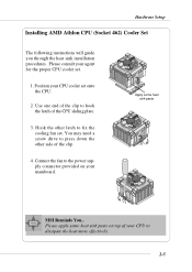
Please consult your mainboard. Connect the fan to the power supply connector provided on top of the clip. 4. Please apply some heat sink paste MSI Reminds You... Hook the other side of your CPU cooler set onto the CPU. 2. Use one end of the CPU sliding plate. 3. You may need a ...
Please consult your mainboard. Connect the fan to the power supply connector provided on top of the clip. 4. Please apply some heat sink paste MSI Reminds You... Hook the other side of your CPU cooler set onto the CPU. 2. Use one end of the CPU sliding plate. 3. You may need a ...
