
User Guide
Page 2
... trademarks of NVIDIA Corporation in the United States and/or other information: http://global.msi.com.tw/index.php? func=faqIndex Contact our technical staff at: http://support.msi.com.tw/ ii Trademarks All trademarks are registered trademarks of AMD Corporation. Our products...2008 Technical Support If a problem arises with your place of its contents. Visit the MSI website for further guidance. Alternatively, please try the following help resources for FAQ, technical guide, BIOS updates, driver updates, and other countries. We take every care in the preparation of...
... trademarks of NVIDIA Corporation in the United States and/or other information: http://global.msi.com.tw/index.php? func=faqIndex Contact our technical staff at: http://support.msi.com.tw/ ii Trademarks All trademarks are registered trademarks of AMD Corporation. Our products...2008 Technical Support If a problem arises with your place of its contents. Visit the MSI website for further guidance. Alternatively, please try the following help resources for FAQ, technical guide, BIOS updates, driver updates, and other countries. We take every care in the preparation of...
User Guide
Page 8
... 1-5 Chapter 2. Hardware Setup 2-1 Quick Components Guide 2-2 CPU (Central Processing Unit 2-3 Memory ...2-6 Power Supply ...2-8 Back Panel ...2-10 Connectors ...2-12 Slots ...2-20 Chapter 3 BIOS Setup 3-1 Entering Setup ...3-2 The Main Menu ...3-4 Standard CMOS Features 3-6 Advanced BIOS Features 3-9 Integrated Peripherals 3-12 Power Management Setup 3-14 H/W Monitor ...3-17 Cell Menu ...3-18 Load Fail-Safe/ Optimized Defaults 3-23...
... 1-5 Chapter 2. Hardware Setup 2-1 Quick Components Guide 2-2 CPU (Central Processing Unit 2-3 Memory ...2-6 Power Supply ...2-8 Back Panel ...2-10 Connectors ...2-12 Slots ...2-20 Chapter 3 BIOS Setup 3-1 Entering Setup ...3-2 The Main Menu ...3-4 Standard CMOS Features 3-6 Advanced BIOS Features 3-9 Integrated Peripherals 3-12 Power Management Setup 3-14 H/W Monitor ...3-17 Cell Menu ...3-18 Load Fail-Safe/ Optimized Defaults 3-23...

User Guide
Page 19
... down the lever. 4. Attach the CPU Fan cable to the CPU fan connector on the top of the retention mechanism. Important 1. Mainboard photos shown in BIOS (Chapter 3). 2. Position the cooling set on the mainboard. 2-5 Fasten down the other end of your dealer to purchase and install them before turning on the...
... down the lever. 4. Attach the CPU Fan cable to the CPU fan connector on the top of the retention mechanism. Important 1. Mainboard photos shown in BIOS (Chapter 3). 2. Position the cooling set on the mainboard. 2-5 Fasten down the other end of your dealer to purchase and install them before turning on the...

User Guide
Page 29
... 1 9 JAUD1 HD Audio Pin Definition DESCRIPTION Microphone - Right channel Analog Port - Hardware Setup Front Panel Audio Connector: JAUD1 This connector allows you must enter the BIOS utility and clear the record. Left channel Jack detection return from the High Definition Audio CODEC jack detection resistor network No control Analog Port - GND...
... 1 9 JAUD1 HD Audio Pin Definition DESCRIPTION Microphone - Right channel Analog Port - Hardware Setup Front Panel Audio Connector: JAUD1 This connector allows you must enter the BIOS utility and clear the record. Left channel Jack detection return from the High Definition Audio CODEC jack detection resistor network No control Analog Port - GND...
User Guide
Page 34
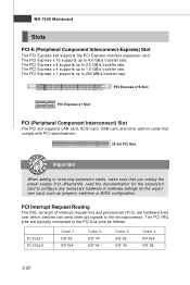
... supply first. The PCI IRQ pins are hardware lines over which devices can send interrupt signals to the PCI bus pins as jumpers, switches or BIOS configuration. The PCI Express x 16 supports up to configure any necessary hardware or software settings for the expansion card, such as follows: PCI Slot 1 PCI...
... supply first. The PCI IRQ pins are hardware lines over which devices can send interrupt signals to the PCI bus pins as jumpers, switches or BIOS configuration. The PCI Express x 16 supports up to configure any necessary hardware or software settings for the expansion card, such as follows: PCI Slot 1 PCI...

User Guide
Page 35
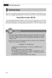
Chapter 3 BIOS Setup BIOS Setup This chapter provides information on the screen during the system booting up, and requests you to change the default settings for optimum use. You may need to run the Setup program when: ² An error message appears on the BIOS Setup program and allows you to run SETUP. ² You want to configure the system for customized features. 3-1
Chapter 3 BIOS Setup BIOS Setup This chapter provides information on the screen during the system booting up, and requests you to change the default settings for optimum use. You may need to run the Setup program when: ² An error message appears on the BIOS Setup program and allows you to run SETUP. ² You want to configure the system for customized features. 3-1
User Guide
Page 36
... the chipset as I = Intel, N = nVidia, and V = VIA. 7th - 8th digit refers to enter Setup, restart the system by simultaneously pressing , , and keys. It is the BIOS version. Therefore, the description may also restart the system by turning it OFF and On or pressing the RESET button. V1.0 refers to the... BIOS version. 013008 refers to enter Setup. W hen the message below appears on the computer and the system will start POST (Power On Self Test) process....
... the chipset as I = Intel, N = nVidia, and V = VIA. 7th - 8th digit refers to enter Setup, restart the system by simultaneously pressing , , and keys. It is the BIOS version. Therefore, the description may also restart the system by turning it OFF and On or pressing the RESET button. V1.0 refers to the... BIOS version. 013008 refers to enter Setup. W hen the message below appears on the computer and the system will start POST (Power On Self Test) process....

User Guide
Page 37
... the control keys to enter values and move from a submenu Increase the numeric value or make changes Decrease the numeric value or make changes to. BIOS Setup Control Keys Enter> Move to the previous item Move to the next item Move to the item in the left hand Move to the...-menu. Then you can use arrow keys ( ↑↓ ) to highlight the field and press to the main menu, just press the . General Help The BIOS setup program provides a General Help screen. You can use and the possible selections for a field parameter. Sub-M enu If you will see is displayed at...
... the control keys to enter values and move from a submenu Increase the numeric value or make changes Decrease the numeric value or make changes to. BIOS Setup Control Keys Enter> Move to the previous item Move to the next item Move to the item in the left hand Move to the...-menu. Then you can use arrow keys ( ↑↓ ) to highlight the field and press to the main menu, just press the . General Help The BIOS setup program provides a General Help screen. You can use and the possible selections for a field parameter. Sub-M enu If you will see is displayed at...
User Guide
Page 38
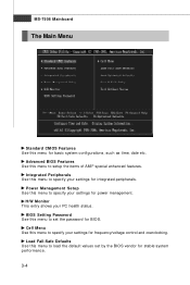
... menu to load the default values set the password for basic system configurations, such as time, date etc. Advanced BIOS Features Use this menu to set by the BIOS vendor for integrated peripherals. BIOS Setting Password Use this menu to setup the items of AMI® special enhanced features. MS-7508 Mainboard The...
... menu to load the default values set the password for basic system configurations, such as time, date etc. Advanced BIOS Features Use this menu to set by the BIOS vendor for integrated peripherals. BIOS Setting Password Use this menu to setup the items of AMI® special enhanced features. MS-7508 Mainboard The...

User Guide
Page 39
Save & Exit Setup Save changes to load the default values set by the mainboard manufacturer specifically for optimal performance of the mainboard. BIOS Setup Load Optimized Defaults Use this menu to CMOS and exit setup. Exit Without Saving Abandon all changes and exit setup. 3-5
Save & Exit Setup Save changes to load the default values set by the mainboard manufacturer specifically for optimal performance of the mainboard. BIOS Setup Load Optimized Defaults Use this menu to CMOS and exit setup. Exit Without Saving Abandon all changes and exit setup. 3-5
User Guide
Page 40
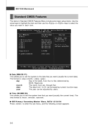
... the item and then use the or keys to the date that you want (usually the current date). year The year can be adjusted by BIOS. day Day of the week, from Sun to enter the sub-menu, and the following screen appears. 3-6
... the item and then use the or keys to the date that you want (usually the current date). year The year can be adjusted by BIOS. day Day of the week, from Sun to enter the sub-menu, and the following screen appears. 3-6
User Guide
Page 41
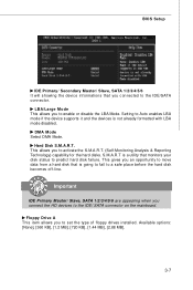
... KB], [1.44 MB], [2.88 MB]. 3-7 Important IDE Primary Master/ Slave, SATA 1/2/3/4/5/6 are appearing when you to the IDE/ SATA connector on the mainboard. Hard Disk S.M.A.R.T. BIOS Setup IDE Primary/ Secondary M aster/ Slave, SATA 1/2/3/4/5/6 It will showing the device informations that monitors your disk status to predict hard disk failure. Setting to...
... KB], [1.44 MB], [2.88 MB]. 3-7 Important IDE Primary Master/ Slave, SATA 1/2/3/4/5/6 are appearing when you to the IDE/ SATA connector on the mainboard. Hard Disk S.M.A.R.T. BIOS Setup IDE Primary/ Secondary M aster/ Slave, SATA 1/2/3/4/5/6 It will showing the device informations that monitors your disk status to predict hard disk failure. Setting to...
User Guide
Page 42
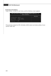
MS-7508 Mainboard System Information Press to enter the sub-menu, and the following screen appears. This sub-menu shows the CPU information, BIOS version and memory status of your system (read only). 3-8
MS-7508 Mainboard System Information Press to enter the sub-menu, and the following screen appears. This sub-menu shows the CPU information, BIOS version and memory status of your system (read only). 3-8
User Guide
Page 43
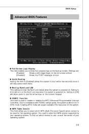
... Table Version This field allows you to show the company logo on . Settings are: [Enabled] Shows a still image (logo) on the numeric keypad. Advanced BIOS Features BIOS Setup Full Screen Logo Display This item enables you to select which version to use the arrow keys on the full screen at boot. [Disabled...
... Table Version This field allows you to show the company logo on . Settings are: [Enabled] Shows a still image (logo) on the numeric keypad. Advanced BIOS Features BIOS Setup Full Screen Logo Display This item enables you to select which version to use the arrow keys on the full screen at boot. [Disabled...
User Guide
Page 45
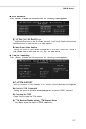
... following screen appears: 1st/ 2nd/ 3rd/ 4th Boot Device The items allow you to set the first/ second/ third/ fourth boot device where BIOS attempts to the system. BIOS Setup Boot Sequence Press to enter the sub-menu and the following screen appears: TCG/TPM SUPPORT Setting the option to [Yes] enables...
... following screen appears: 1st/ 2nd/ 3rd/ 4th Boot Device The items allow you to set the first/ second/ third/ fourth boot device where BIOS attempts to the system. BIOS Setup Boot Sequence Press to enter the sub-menu and the following screen appears: TCG/TPM SUPPORT Setting the option to [Yes] enables...
User Guide
Page 47
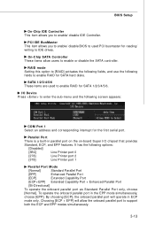
... [Normal]. SATA 1/2/3/4/5/6 These items are used PCI busmaster for SATA 1/2/3/4/5/6. Choosing [ECP + EPP] will operate in ECP mode only. BIOS Setup On-Chip IDE Controller This item allows you to enable/ disable BIOS to used to enable RAID for reading/ writing to enable/ disable IDE Controller. On-Chip SATA Controller These items...
... [Normal]. SATA 1/2/3/4/5/6 These items are used PCI busmaster for SATA 1/2/3/4/5/6. Choosing [ECP + EPP] will operate in ECP mode only. BIOS Setup On-Chip IDE Controller This item allows you to enable/ disable BIOS to used to enable RAID for reading/ writing to enable/ disable IDE Controller. On-Chip SATA Controller These items...
User Guide
Page 48
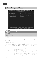
... is lost (CPU or chipset) and hardware main- ACPI Function This item is to restore the system when a "wake up" event occurs. 3-14 If your BIOS supports S3 sleep mode. tings are available only when your operating system is ACPI-aware, such as W indows 2000/ XP , you can choose to enter...
... is lost (CPU or chipset) and hardware main- ACPI Function This item is to restore the system when a "wake up" event occurs. 3-14 If your BIOS supports S3 sleep mode. tings are available only when your operating system is ACPI-aware, such as W indows 2000/ XP , you can choose to enter...
User Guide
Page 49
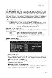
... AC Power Loss This item specifies whether your system will need an VGA driver to initialize the VGA card. Wake Up Event By Setting to [BIOS] activates the following fields, and use the following sub-menu appears. Therefore, if the VGA driver of the PS/2 keyboard is detected. 3-15 ... of the card does not support the initialization feature, the display may work abnormally or not function after a power failure or interrupt occurs. BIOS Setup Re-Call VGA BIOS From S3 W hen ACPI Standby State is set the wake up events. Settings are : [Off] Always leaves the computer in the power...
... AC Power Loss This item specifies whether your system will need an VGA driver to initialize the VGA card. Wake Up Event By Setting to [BIOS] activates the following fields, and use the following sub-menu appears. Therefore, if the VGA driver of the PS/2 keyboard is detected. 3-15 ... of the card does not support the initialization feature, the display may work abnormally or not function after a power failure or interrupt occurs. BIOS Setup Re-Call VGA BIOS From S3 W hen ACPI Standby State is set the wake up events. Settings are : [Off] Always leaves the computer in the power...
User Guide
Page 51
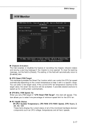
... the field to keep it with in . CPU Smart FAN Target The mainboard provides the Smart Fan function which can select a fan target value. H/W Monitor BIOS Setup Chassis Intrusion The field enables or disables the feature of the monitored hardware devices/ components such as CPU voltage, temperatures and all of recording...
... the field to keep it with in . CPU Smart FAN Target The mainboard provides the Smart Fan function which can select a fan target value. H/W Monitor BIOS Setup Chassis Intrusion The field enables or disables the feature of the monitored hardware devices/ components such as CPU voltage, temperatures and all of recording...

User Guide
Page 53
...of overclocking options. By the way, if you need to be working properly, it is required to overclocking regularly first. Run BIOS Setup, and select Cell Menu. Enter Power Options Properties tag, and select Minimal Power Management under Power schemes. 3-19 Under... Cell Menu, find the PC appears to disable the Dynamic OverClocking first. We suggest user to "Enable." 2. BIOS Setup [Disabled] [Private] [Sergeant] [Captain] [Colonel] [General] [Commander] Disable Dynamic Overclocking. 1st level of overclocking, increasing the frequency by...
...of overclocking options. By the way, if you need to be working properly, it is required to overclocking regularly first. Run BIOS Setup, and select Cell Menu. Enter Power Options Properties tag, and select Minimal Power Management under Power schemes. 3-19 Under... Cell Menu, find the PC appears to disable the Dynamic OverClocking first. We suggest user to "Enable." 2. BIOS Setup [Disabled] [Private] [Sergeant] [Captain] [Colonel] [General] [Commander] Disable Dynamic Overclocking. 1st level of overclocking, increasing the frequency by...


