
User Guide
Page 2
...support.msi.com.tw/ ii Trademarks All trademarks are registered trademarks of their respective owners. W indows® 95/98/2000/NT/XP are the properties of Microsoft Corporation. Award® is a registered trademark of M ICRO-STAR INTERNATIONAL. Copyright Notice The material in this document, but no solution can be obtained from the user's manual... First release for further guidance. Visit the MSI website for FAQ, technical guide, BIOS updates, driver updates, and other countries. AMI® is the intellectual property of Phoenix Technologies Ltd. We take every care in the ...
...support.msi.com.tw/ ii Trademarks All trademarks are registered trademarks of their respective owners. W indows® 95/98/2000/NT/XP are the properties of Microsoft Corporation. Award® is a registered trademark of M ICRO-STAR INTERNATIONAL. Copyright Notice The material in this document, but no solution can be obtained from the user's manual... First release for further guidance. Visit the MSI website for FAQ, technical guide, BIOS updates, driver updates, and other countries. AMI® is the intellectual property of Phoenix Technologies Ltd. We take every care in the ...
User Guide
Page 8
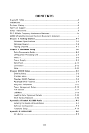
... Guide 2-2 CPU (Central Processing Unit 2-3 Memory ...2-6 Power Supply ...2-8 Back Panel ...2-10 Connectors ...2-12 Slots ...2-20 Chapter 3 BIOS Setup 3-1 Entering Setup ...3-2 The Main Menu ...3-4 Standard CMOS Features 3-6 Advanced BIOS Features 3-9 Integrated Peripherals 3-12 Power Management Setup 3-14 H/W Monitor ...3-17 Cell Menu ...3-18 Load Fail-Safe/ Optimized Defaults 3-23 BIOS Setting Password 3-24 Appendix A Realtek ALC888 Audio A-1 Installing the Realtek HD Audio Driver A-2 Software Configuration A-4 Hardware Setup A-19 Appendix B nVidia RAID B-1 Introduction...
... Guide 2-2 CPU (Central Processing Unit 2-3 Memory ...2-6 Power Supply ...2-8 Back Panel ...2-10 Connectors ...2-12 Slots ...2-20 Chapter 3 BIOS Setup 3-1 Entering Setup ...3-2 The Main Menu ...3-4 Standard CMOS Features 3-6 Advanced BIOS Features 3-9 Integrated Peripherals 3-12 Power Management Setup 3-14 H/W Monitor ...3-17 Cell Menu ...3-18 Load Fail-Safe/ Optimized Defaults 3-23 BIOS Setting Password 3-24 Appendix A Realtek ALC888 Audio A-1 Installing the Realtek HD Audio Driver A-2 Software Configuration A-4 Hardware Setup A-19 Appendix B nVidia RAID B-1 Introduction...
User Guide
Page 11
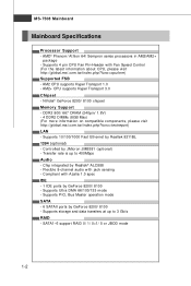
.../ 8100 - Compliant with Azalia 1.0 spec IDE - 1 IDE ports by Realtek 8211BL 1394 (optional) - SATA1~6 support RAID 0/ 1/ 0+1/ 5 or JBOD mode 1-2 MS-7508 Mainboard Mainboard Specifications Processor Support - t w / i nde x . p hp?f unc =t e s t re por t ) LAN - AM2 CPU supports Hyper Transport 1.0 - c om. Supports Ultra DMA 66/100/133 mode - Transfer rate is up to 400Mbps Audio - Supports PIO, Bus Master operation mode SATA - 6 SATAII ports by GeForce 8200/ 8100 - AMD® Phenom/ Athlon 64/ Sempron series processors in AM2/AM2+ package...
.../ 8100 - Compliant with Azalia 1.0 spec IDE - 1 IDE ports by Realtek 8211BL 1394 (optional) - SATA1~6 support RAID 0/ 1/ 0+1/ 5 or JBOD mode 1-2 MS-7508 Mainboard Mainboard Specifications Processor Support - t w / i nde x . p hp?f unc =t e s t re por t ) LAN - AM2 CPU supports Hyper Transport 1.0 - c om. Supports Ultra DMA 66/100/133 mode - Transfer rate is up to 400Mbps Audio - Supports PIO, Bus Master operation mode SATA - 6 SATAII ports by GeForce 8200/ 8100 - AMD® Phenom/ Athlon 64/ Sempron series processors in AM2/AM2+ package...
User Guide
Page 12
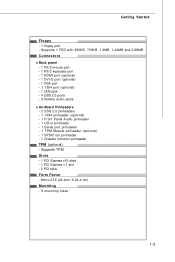
... Back panel - 1 PS/2 mouse port - 1 PS/2 keyboard port - 1 HDMI port (optional) - 1 DVI-D port (optional) - 1 VGA port - 1 1394 port (optional) - 1 LAN jack - 4 USB 2.0 ports - 6 flexible audio jacks On-Board Pinheaders - 2 USB 2.0 pinheaders - 1 1394 pinheader (optional) - 1 Front Panel Audio pinheader - 1 CD-in pinheader - 1 Serial port pinheader - 1 TPM Module pinheader (optional) - 1 SPDIF-out pinheader - 1 Chassis Intrusion pinheader TPM (optional) - Supports TPM Slots - 1 PCI Express x16 slots - 1 PCI Express x 1 slot - 2 PCI slots Form Factor - Getting Started Floppy - 1 floppy port...
... Back panel - 1 PS/2 mouse port - 1 PS/2 keyboard port - 1 HDMI port (optional) - 1 DVI-D port (optional) - 1 VGA port - 1 1394 port (optional) - 1 LAN jack - 4 USB 2.0 ports - 6 flexible audio jacks On-Board Pinheaders - 2 USB 2.0 pinheaders - 1 1394 pinheader (optional) - 1 Front Panel Audio pinheader - 1 CD-in pinheader - 1 Serial port pinheader - 1 TPM Module pinheader (optional) - 1 SPDIF-out pinheader - 1 Chassis Intrusion pinheader TPM (optional) - Supports TPM Slots - 1 PCI Express x16 slots - 1 PCI Express x 1 slot - 2 PCI slots Form Factor - Getting Started Floppy - 1 floppy port...
User Guide
Page 22
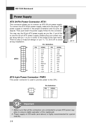
... right hand). Then push down the power supply firmly into the connector. MS-7508 Mainboard Power Supply ATX 24-Pin Power Connector: ATX1 This connector allows you to ensure stable operation of the mainboard. 2. You may use the 20-pin ATX power supply as you like to use the 20-pin ATX power supply, please plug your power supply along with pin 1 & pin 13 (refer to avoid wrong installation. Pin Definition 12 24 PIN SIGNAL PIN SIGNAL ATX1 1 13 1 +3.3V 13...
... right hand). Then push down the power supply firmly into the connector. MS-7508 Mainboard Power Supply ATX 24-Pin Power Connector: ATX1 This connector allows you to ensure stable operation of the mainboard. 2. You may use the 20-pin ATX power supply as you like to use the 20-pin ATX power supply, please plug your power supply along with pin 1 & pin 13 (refer to avoid wrong installation. Pin Definition 12 24 PIN SIGNAL PIN SIGNAL ATX1 1 13 1 +3.3V 13...
User Guide
Page 24
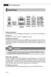
...) connector allows you power-on the system. MS-7508 Mainboard Back Panel Mouse (optional) HDMI Port Keyboard VGA Port (optional) LAN 1394 Port Line-In RS-Out Line-Out CS-Out DVI-D Port (optional) USB Port USB Port Mic SS-Out M ouse/K ey boar d The standard PS/2® mouse/keyboard DIN connector is for more information.) 1394 Port (optional) The IEEE1394 port on the back panel provides connection to IEEE1394 devices. 2-10 To connect an LCD monitor, simply plug your monitor cable...
...) connector allows you power-on the system. MS-7508 Mainboard Back Panel Mouse (optional) HDMI Port Keyboard VGA Port (optional) LAN 1394 Port Line-In RS-Out Line-Out CS-Out DVI-D Port (optional) USB Port USB Port Mic SS-Out M ouse/K ey boar d The standard PS/2® mouse/keyboard DIN connector is for more information.) 1394 Port (optional) The IEEE1394 port on the back panel provides connection to IEEE1394 devices. 2-10 To connect an LCD monitor, simply plug your monitor cable...
User Guide
Page 26
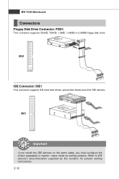
FDD1 IDE Connector: IDE1 This connector supports IDE hard disk drives, optical disk drives and other IDE devices. MS-7508 Mainboard Connectors Floppy Disk Drive Connector: FDD1 This connector supports 360KB, 720KB, 1.2MB, 1.44MB or 2.88MB floppy disk drive. IDE1 Important If you install two IDE devices on the same cable, you must configure the drives separately to IDE device's documentation supplied by setting jumpers. Refer to master / slave mode by the vendors for jumper setting instructions. 2-12
FDD1 IDE Connector: IDE1 This connector supports IDE hard disk drives, optical disk drives and other IDE devices. MS-7508 Mainboard Connectors Floppy Disk Drive Connector: FDD1 This connector supports 360KB, 720KB, 1.2MB, 1.44MB or 2.88MB floppy disk drive. IDE1 Important If you install two IDE devices on the same cable, you must configure the drives separately to IDE device's documentation supplied by setting jumpers. Refer to master / slave mode by the vendors for jumper setting instructions. 2-12
User Guide
Page 28
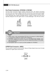
MS-7508 Mainboard Fan Power Connectors: CPUFAN1, SYSFAN1 The fan power connectors support system cooling fan with 3 or 4 pins are both available for CPUFAN1. S/PDIF-Out Connector: JSPD1 This connector is used to the +12V; W hen connecting the wire to the connectors, always note that will automatically control the CPU fan speed according to the recommended CPU fans at processor's official website or consult the vendors for digital audio transmission. CPUFAN1 supports fan control. You can install Dual Core Center utility that...
MS-7508 Mainboard Fan Power Connectors: CPUFAN1, SYSFAN1 The fan power connectors support system cooling fan with 3 or 4 pins are both available for CPUFAN1. S/PDIF-Out Connector: JSPD1 This connector is used to the +12V; W hen connecting the wire to the connectors, always note that will automatically control the CPU fan speed according to the recommended CPU fans at processor's official website or consult the vendors for digital audio transmission. CPUFAN1 supports fan control. You can install Dual Core Center utility that...
User Guide
Page 34
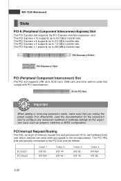
...Interconnect-Express) Slot The PCI Express slot supports the PCI Express interface expansion card. PCI Express x16 Slot PCI Express x1 Slot PCI (Peripheral Component Interconnect) Slot The PCI slot supports LAN card, SCSI card, USB card, and other add-on cards that comply with PCI specifications. 32-bit PCI Slot Important When adding or removing expansion cards, make sure that you unplug the power supply first. The PCI Express x 8 supports up to 1.0 GB/s transfer rate. The PCI Express x 4 supports up to configure any necessary hardware or software settings for the expansion card to...
...Interconnect-Express) Slot The PCI Express slot supports the PCI Express interface expansion card. PCI Express x16 Slot PCI Express x1 Slot PCI (Peripheral Component Interconnect) Slot The PCI slot supports LAN card, SCSI card, USB card, and other add-on cards that comply with PCI specifications. 32-bit PCI Slot Important When adding or removing expansion cards, make sure that you unplug the power supply first. The PCI Express x 8 supports up to 1.0 GB/s transfer rate. The PCI Express x 4 supports up to configure any necessary hardware or software settings for the expansion card to...
User Guide
Page 41
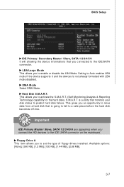
Setting to Auto enables LBA mode if the device supports it and the devices is going to fail to a safe place before the hard disk becomes off-line. Floppy Drive A This item allows you connect the HD devices to the IDE/ SATA connector on the mainboard. Hard Disk S.M.A.R.T. Important IDE Primary Master/ Slave, SATA 1/2/3/4/5/6 are appearing when you to set the type of floppy drives installed. DM A M ode Select DMA Mode. This gives you connected to the IDE/SATA connector. Available options: [None], [360...
Setting to Auto enables LBA mode if the device supports it and the devices is going to fail to a safe place before the hard disk becomes off-line. Floppy Drive A This item allows you connect the HD devices to the IDE/ SATA connector on the mainboard. Hard Disk S.M.A.R.T. Important IDE Primary Master/ Slave, SATA 1/2/3/4/5/6 are appearing when you to set the type of floppy drives installed. DM A M ode Select DMA Mode. This gives you connected to the IDE/SATA connector. Available options: [None], [360...
User Guide
Page 43
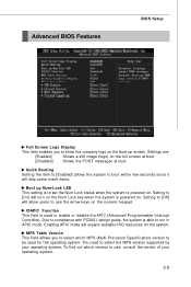
... is powered on. Enabling APIC mode will expand available IRQ resources for the operating system. To find out which MPS (Multi-Processor Specification) version to use the arrow keys on the numeric keypad. MPS Table Version This field allows you to show the company logo on the boot-up Num-Lock LED This setting is used for the system. Advanced BIOS Features BIOS Setup Full Screen Logo Display...
... is powered on. Enabling APIC mode will expand available IRQ resources for the operating system. To find out which MPS (Multi-Processor Specification) version to use the arrow keys on the numeric keypad. MPS Table Version This field allows you to show the company logo on the boot-up Num-Lock LED This setting is used for the system. Advanced BIOS Features BIOS Setup Full Screen Logo Display...
User Guide
Page 44
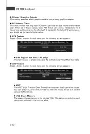
...) This item is your primary graphics adapter. PCI Latency Timer This item controls how long each PCI device can hold the bus before another takes over. This setting controls the exact memory size shared to enable or disable the SVM (Secure Virtual Machine) mode. CPU Feature Press to enter the sub-menu and the following screen appears: HPET The HPET (High Precision Event Timers) is a component that is part of the chipset.
...) This item is your primary graphics adapter. PCI Latency Timer This item controls how long each PCI device can hold the bus before another takes over. This setting controls the exact memory size shared to enable or disable the SVM (Secure Virtual Machine) mode. CPU Feature Press to enter the sub-menu and the following screen appears: HPET The HPET (High Precision Event Timers) is a component that is part of the chipset.
User Guide
Page 46
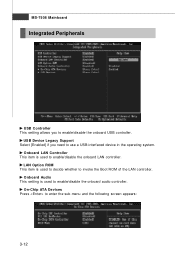
Onboard Audio This setting is used to enable/disable the onboard LAN controller. Onboard LAN Controller This item is used to decide whether to invoke the Boot ROM of the LAN controller. LAN Option ROM This item is used to enable/disable the onboard audio controller. On-Chip ATA Devices Press to enter the sub-menu and the following screen appears: 3-12 USB Device Legacy Support Select [Enabled] if you to enable/disable the onboard USB controller. MS-7508 Mainboard Integrated Peripherals USB Controller This setting allows you need to use a USB-interfaced device in the operating ...
Onboard Audio This setting is used to enable/disable the onboard LAN controller. Onboard LAN Controller This item is used to decide whether to invoke the Boot ROM of the LAN controller. LAN Option ROM This item is used to enable/disable the onboard audio controller. On-Chip ATA Devices Press to enter the sub-menu and the following screen appears: 3-12 USB Device Legacy Support Select [Enabled] if you to enable/disable the onboard USB controller. MS-7508 Mainboard Integrated Peripherals USB Controller This setting allows you need to use a USB-interfaced device in the operating ...
User Guide
Page 47
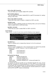
SATA 1/2/3/4/5/6 These items are used PCI busmaster for reading/ writing to enable RAID for SATA hard disks. I /O chipset that provides Standard, ECP, and EPP features. BIOS Setup On-Chip IDE Controller This item allows you to enable/ disable BIOS to used to enable/ disable IDE Controller. On-Chip SATA Controller These items allow the onboard parallel port to enable or disable the SATA controller. Parallel Port There is a built-in ECP mode only. By choosing [ECP], the onboard parallel port will allow users to support both the ECP...
SATA 1/2/3/4/5/6 These items are used PCI busmaster for reading/ writing to enable RAID for SATA hard disks. I /O chipset that provides Standard, ECP, and EPP features. BIOS Setup On-Chip IDE Controller This item allows you to enable/ disable BIOS to used to enable/ disable IDE Controller. On-Chip SATA Controller These items allow the onboard parallel port to enable or disable the SATA controller. Parallel Port There is a built-in ECP mode only. By choosing [ECP], the onboard parallel port will allow users to support both the ECP...
User Guide
Page 51
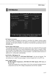
H/W Monitor BIOS Setup Chassis Intrusion The field enables or disables the feature of the field will automatically return to [Enabled] later. The setting of recording the chassis intrusion status and issuing a warning message if the chassis is once opened. If the current CPU fan temperature reaches to speed up for the CPU fan. CPU Smart FAN Target The mainboard provides the Smart Fan function which can select a fan target value. PC Health Status CPU/ System...
H/W Monitor BIOS Setup Chassis Intrusion The field enables or disables the feature of the field will automatically return to [Enabled] later. The setting of recording the chassis intrusion status and issuing a warning message if the chassis is once opened. If the current CPU fan temperature reaches to speed up for the CPU fan. CPU Smart FAN Target The mainboard provides the Smart Fan function which can select a fan target value. PC Health Status CPU/ System...
User Guide
Page 55
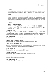
... link voltage. 3-21 NB Voltage (V) Adjust the North Bridge chipset voltage. DRAM Voltage (V) Adjusting the memory voltage can increase the memory speed. Auto Disable DRAM/PCI Clock W hen set to [Enabled], the system will remove (turn off) clocks from and write to [Manual], this field is installed in MHz). This item applies only when synchronous DRAM is adjustable. Selecting [2T] makes SDRAM signal controller run at 2T rate. tRP W hen the DRAM Timing Mode sets to memory cell...
... link voltage. 3-21 NB Voltage (V) Adjust the North Bridge chipset voltage. DRAM Voltage (V) Adjusting the memory voltage can increase the memory speed. Auto Disable DRAM/PCI Clock W hen set to [Enabled], the system will remove (turn off) clocks from and write to [Manual], this field is installed in MHz). This item applies only when synchronous DRAM is adjustable. Selecting [2T] makes SDRAM signal controller run at 2T rate. tRP W hen the DRAM Timing Mode sets to memory cell...
User Guide
Page 60
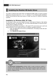
... on W indows® XP environment and could look slightly different if you must install W indows® 2000 Service Pack4 or later before installing the driver. A-2 The setup screen will automatically appear. 2. Click here Important The HD Audio Configuration software utility is under continuous update to install the drivers for different operating systems. Installation for Windows 2000/ XP/ Vista For W indows® 2000, you can get...
... on W indows® XP environment and could look slightly different if you must install W indows® 2000 Service Pack4 or later before installing the driver. A-2 The setup screen will automatically appear. 2. Click here Important The HD Audio Configuration software utility is under continuous update to install the drivers for different operating systems. Installation for Windows 2000/ XP/ Vista For W indows® 2000, you can get...
User Guide
Page 83
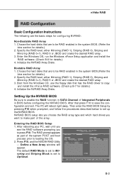
..., use the floppy disk that are to save the configuration and exit. NVRAID BIOS setup lets you choose the RAID array type and which hard drives you to copy and install the nForce RAID software. (Check p.B-7 for details.) 2. Press F10, and the NVIDIA RAID Utility --- Specify the RAID level, either Mirroring (RAID 1), Striping (RAID 0), Striping and Mirroring (RAID 0+1), RAID 5 or JBOD and create the desired RAID array. 3. Define a New Array window will...
..., use the floppy disk that are to save the configuration and exit. NVRAID BIOS setup lets you choose the RAID array type and which hard drives you to copy and install the nForce RAID software. (Check p.B-7 for details.) 2. Press F10, and the NVIDIA RAID Utility --- Specify the RAID level, either Mirroring (RAID 1), Striping (RAID 0), Striping and Mirroring (RAID 0+1), RAID 5 or JBOD and create the desired RAID array. 3. Define a New Array window will...
User Guide
Page 87
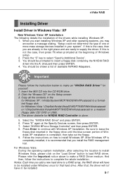
... ENTER. 4. Follow the instructions on how to select "Specify Additional Device". 3. Please refer the Important notice above to a medium (floppy disk/ CD/ DVD or USB). 4. You should be installed under Windows once for that hard drive. Copy all the contents in the for Windows Vista \\ChipSet\Nvidia\Vista32\MCP78\IDE\WinVista\sataraid or \\ChipSet\Nvidia\Vista64\MCP78\IDE\WinVista\sataraid to make an "NVIDIA RAID Driver" for NVIDIA RAID Controller...
... ENTER. 4. Follow the instructions on how to select "Specify Additional Device". 3. Please refer the Important notice above to a medium (floppy disk/ CD/ DVD or USB). 4. You should be installed under Windows once for that hard drive. Copy all the contents in the for Windows Vista \\ChipSet\Nvidia\Vista32\MCP78\IDE\WinVista\sataraid or \\ChipSet\Nvidia\Vista64\MCP78\IDE\WinVista\sataraid to make an "NVIDIA RAID Driver" for NVIDIA RAID Controller...
User Guide
Page 99
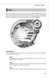
... to enter sub-menu to make further configuration or to enable or disable the Dynamic Overclocking Technology. C-3 Dual Core Center Main Before using this utility, we have to remind you install a graphics card of other brand, only hardware status of the MSI mainboard would be available. MB Click MB button to read current CPU temperature, FSB and CPU clock of graphics card will show below . VGA Click VGA button to read current GPU temperature, GPU clock and memory clock of mainboard will...
... to enter sub-menu to make further configuration or to enable or disable the Dynamic Overclocking Technology. C-3 Dual Core Center Main Before using this utility, we have to remind you install a graphics card of other brand, only hardware status of the MSI mainboard would be available. MB Click MB button to read current CPU temperature, FSB and CPU clock of graphics card will show below . VGA Click VGA button to read current GPU temperature, GPU clock and memory clock of mainboard will...

