User Guide
Page 2
...logo, DualNet, and nForce are registered trademarks or trademarks of NVIDIA Corporation in the United States and/or other information: http://global.msi.com.tw/index.php? Netware® is a registered trademark of Phoenix Technologies Ltd. Award® is a registered trademark of ...as to make changes without notice. Alternatively, please try the following help resources for FAQ, technical guide, BIOS updates, driver updates, and other countries. Visit the MSI website for further guidance. AMD, Athlon™, Athlon™ XP, Thoroughbred™, and Duron™ are...
...logo, DualNet, and nForce are registered trademarks or trademarks of NVIDIA Corporation in the United States and/or other information: http://global.msi.com.tw/index.php? Netware® is a registered trademark of Phoenix Technologies Ltd. Award® is a registered trademark of ...as to make changes without notice. Alternatively, please try the following help resources for FAQ, technical guide, BIOS updates, driver updates, and other countries. Visit the MSI website for further guidance. AMD, Athlon™, Athlon™ XP, Thoroughbred™, and Duron™ are...
User Guide
Page 8
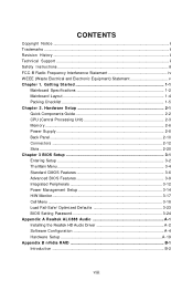
...Central Processing Unit 2-3 Memory ...2-6 Power Supply ...2-8 Back Panel ...2-10 Connectors ...2-12 Slots ...2-20 Chapter 3 BIOS Setup 3-1 Entering Setup ...3-2 The Main Menu ...3-4 Standard CMOS Features 3-6 Advanced BIOS Features 3-9 Integrated Peripherals 3-12 Power Management Setup 3-14 H/W Monitor ...3-17 Cell Menu ...3-18 Load Fail-...Safe/ Optimized Defaults 3-23 BIOS Setting Password 3-24 Appendix A Realtek ALC888 Audio A-1 Installing the Realtek HD Audio Driver A-2 Software Configuration A-4 ...
...Central Processing Unit 2-3 Memory ...2-6 Power Supply ...2-8 Back Panel ...2-10 Connectors ...2-12 Slots ...2-20 Chapter 3 BIOS Setup 3-1 Entering Setup ...3-2 The Main Menu ...3-4 Standard CMOS Features 3-6 Advanced BIOS Features 3-9 Integrated Peripherals 3-12 Power Management Setup 3-14 H/W Monitor ...3-17 Cell Menu ...3-18 Load Fail-...Safe/ Optimized Defaults 3-23 BIOS Setting Password 3-24 Appendix A Realtek ALC888 Audio A-1 Installing the Realtek HD Audio Driver A-2 Software Configuration A-4 ...

User Guide
Page 19
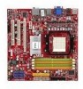
... installing the CPU, make sure the CPU has a heat sink and a cooling fan attached on the top of the retention mechanism. Mainboard photos shown in BIOS (Chapter 3). 2. Attach the CPU Fan cable to prevent overheating. Position the cooling set on the top to the CPU fan connector on the computer. Fasten...
... installing the CPU, make sure the CPU has a heat sink and a cooling fan attached on the top of the retention mechanism. Mainboard photos shown in BIOS (Chapter 3). 2. Attach the CPU Fan cable to prevent overheating. Position the cooling set on the top to the CPU fan connector on the computer. Fasten...

User Guide
Page 29
... 2 10 1 9 JAUD1 HD Audio Pin Definition DESCRIPTION Microphone - GND R L CD_IN1 2-15 Hardware Setup Front Panel Audio Connector: JAUD1 This connector allows you must enter the BIOS utility and clear the record.
... 2 10 1 9 JAUD1 HD Audio Pin Definition DESCRIPTION Microphone - GND R L CD_IN1 2-15 Hardware Setup Front Panel Audio Connector: JAUD1 This connector allows you must enter the BIOS utility and clear the record.
User Guide
Page 34
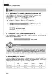
.... PCI Interrupt Request Routing The IRQ, acronym of interrupt request line and pronounced I-R-Q, are typically connected to the PCI bus pins as jumpers, switches or BIOS configuration. The PCI Express x 1 supports up to 250 MB/s transfer rate. The PCI Express x 16 supports up to 4.0 GB/s transfer rate. The PCI Express x 8 supports...
.... PCI Interrupt Request Routing The IRQ, acronym of interrupt request line and pronounced I-R-Q, are typically connected to the PCI bus pins as jumpers, switches or BIOS configuration. The PCI Express x 1 supports up to 250 MB/s transfer rate. The PCI Express x 16 supports up to 4.0 GB/s transfer rate. The PCI Express x 8 supports...

User Guide
Page 35
Chapter 3 BIOS Setup BIOS Setup This chapter provides information on the screen during the system booting up, and requests you to change the default settings for optimum use. You may need to run the Setup program when: ² An error message appears on the BIOS Setup program and allows you to run SETUP. ² You want to configure the system for customized features. 3-1
Chapter 3 BIOS Setup BIOS Setup This chapter provides information on the screen during the system booting up, and requests you to change the default settings for optimum use. You may need to run the Setup program when: ² An error message appears on the BIOS Setup program and allows you to run SETUP. ² You want to configure the system for customized features. 3-1

User Guide
Page 36
...by simultaneously pressing , , and keys. Upon boot-up, the 1st line appearing after the memory count is usually in this BIOS was released. 3-2 V1.0 refers to the BIOS version. 013008 refers to enter Setup. W hen the message below appears on the computer and the system will start POST (... screen, press key to the date this chapter are under continuous update for reference only. 2. The items under each BIOS category described in the format: A7508NMS V1.0 013008 where: 1st digit refers to BIOS maker as A = AMI, W = AWARD, and P = PHOENIX. 2nd - 5th digit refers to the model number....
...by simultaneously pressing , , and keys. Upon boot-up, the 1st line appearing after the memory count is usually in this BIOS was released. 3-2 V1.0 refers to the BIOS version. 013008 refers to enter Setup. W hen the message below appears on the computer and the system will start POST (... screen, press key to the date this chapter are under continuous update for reference only. 2. The items under each BIOS category described in the format: A7508NMS V1.0 013008 where: 1st digit refers to BIOS maker as A = AMI, W = AWARD, and P = PHOENIX. 2nd - 5th digit refers to the model number....

User Guide
Page 37
... menu you want to return to the main menu, just press the . A sub-menu contains additional options for the highlighted item. General Help The BIOS setup program provides a General Help screen. You can use the control keys to enter values and move from a submenu Increase the numeric value or make... changes Decrease the numeric value or make changes to. BIOS Setup Control Keys Enter> Move to the previous item Move to the next item Move to the item in the right hand Select the item...
... menu you want to return to the main menu, just press the . A sub-menu contains additional options for the highlighted item. General Help The BIOS setup program provides a General Help screen. You can use the control keys to enter values and move from a submenu Increase the numeric value or make... changes Decrease the numeric value or make changes to. BIOS Setup Control Keys Enter> Move to the previous item Move to the next item Move to the item in the right hand Select the item...
User Guide
Page 38
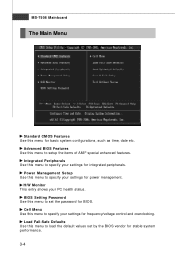
... Use this menu to specify your PC health status. Cell Menu Use this menu to set by the BIOS vendor for integrated peripherals. Integrated Peripherals Use this menu to load the default values set the password for frequency/voltage control and overclocking. Load ...Fail-Safe Defaults Use this menu to specify your settings for BIOS. MS-7508 Mainboard The Main Menu Standard CMOS Features Use this menu for power management. Power Management Setup Use this menu to setup the ...
... Use this menu to specify your PC health status. Cell Menu Use this menu to set by the BIOS vendor for integrated peripherals. Integrated Peripherals Use this menu to load the default values set the password for frequency/voltage control and overclocking. Load ...Fail-Safe Defaults Use this menu to specify your settings for BIOS. MS-7508 Mainboard The Main Menu Standard CMOS Features Use this menu for power management. Power Management Setup Use this menu to setup the ...

User Guide
Page 39
Save & Exit Setup Save changes to load the default values set by the mainboard manufacturer specifically for optimal performance of the mainboard. Exit Without Saving Abandon all changes and exit setup. 3-5 BIOS Setup Load Optimized Defaults Use this menu to CMOS and exit setup.
Save & Exit Setup Save changes to load the default values set by the mainboard manufacturer specifically for optimal performance of the mainboard. Exit Without Saving Abandon all changes and exit setup. 3-5 BIOS Setup Load Optimized Defaults Use this menu to CMOS and exit setup.

User Guide
Page 40
month The month from Sun to 31 can be keyed by users. date The date from 1 to Sat, determined by BIOS. year The year can be adjusted by numeric function keys. IDE Primary/ Secondary M aster/ Slave, SATA 1/2/3/4/5/6 Press to the date that you want (usually the ...
month The month from Sun to 31 can be keyed by users. date The date from 1 to Sat, determined by BIOS. year The year can be adjusted by numeric function keys. IDE Primary/ Secondary M aster/ Slave, SATA 1/2/3/4/5/6 Press to the date that you want (usually the ...

User Guide
Page 41
... you connect the HD devices to the IDE/ SATA connector on the mainboard. Floppy Drive A This item allows you connected to the IDE/SATA connector. BIOS Setup IDE Primary/ Secondary M aster/ Slave, SATA 1/2/3/4/5/6 It will showing the device informations that monitors your disk status to Auto enables LBA mode if the...
... you connect the HD devices to the IDE/ SATA connector on the mainboard. Floppy Drive A This item allows you connected to the IDE/SATA connector. BIOS Setup IDE Primary/ Secondary M aster/ Slave, SATA 1/2/3/4/5/6 It will showing the device informations that monitors your disk status to Auto enables LBA mode if the...

User Guide
Page 42
This sub-menu shows the CPU information, BIOS version and memory status of your system (read only). 3-8 MS-7508 Mainboard System Information Press to enter the sub-menu, and the following screen appears.
This sub-menu shows the CPU information, BIOS version and memory status of your system (read only). 3-8 MS-7508 Mainboard System Information Press to enter the sub-menu, and the following screen appears.
User Guide
Page 43
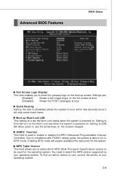
Enabling APIC mode will skip some check items. Boot up screen. Advanced BIOS Features BIOS Setup Full Screen Logo Display This item enables you to select which version to use the arrow keys on the full screen at boot. [Disabled] ...
Enabling APIC mode will skip some check items. Boot up screen. Advanced BIOS Features BIOS Setup Full Screen Logo Display This item enables you to select which version to use the arrow keys on the full screen at boot. [Disabled] ...

User Guide
Page 45
... to [Yes] allows the system to try to boot from other device. If the system fails to boot from the 1st/ 2nd/ 3rd boot device. BIOS Setup Boot Sequence Press to enter the sub-menu and the following screen appears: TCG/TPM SUPPORT Setting the option to [Yes] enables TPM (Trusted... and the following screen appears: 1st/ 2nd/ 3rd/ 4th Boot Device The items allow you to set the first/ second/ third/ fourth boot device where BIOS attempts to the system.
... to [Yes] allows the system to try to boot from other device. If the system fails to boot from the 1st/ 2nd/ 3rd boot device. BIOS Setup Boot Sequence Press to enter the sub-menu and the following screen appears: TCG/TPM SUPPORT Setting the option to [Yes] enables TPM (Trusted... and the following screen appears: 1st/ 2nd/ 3rd/ 4th Boot Device The items allow you to set the first/ second/ third/ fourth boot device where BIOS attempts to the system.

User Guide
Page 47
... and EPP modes simultaneously. 3-13 I /O chipset that provides Standard, ECP, and EPP features. Choosing [ECP + EPP] will operate in the EPP mode simultaneously, choose [EPP]. BIOS Setup On-Chip IDE Controller This item allows you to enable/ disable...
... and EPP modes simultaneously. 3-13 I /O chipset that provides Standard, ECP, and EPP features. Choosing [ECP + EPP] will operate in the EPP mode simultaneously, choose [EPP]. BIOS Setup On-Chip IDE Controller This item allows you to enable/ disable...
User Guide
Page 48
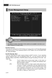
... mode is ACPI-aware, such as W indows 2000/ XP , you can choose to enter the Standby mode in formation of this field. Set- If your BIOS supports S3 sleep mode.
... mode is ACPI-aware, such as W indows 2000/ XP , you can choose to enter the Standby mode in formation of this field. Set- If your BIOS supports S3 sleep mode.

User Guide
Page 49
...S3 (Suspend to set to the status before power failure or interrupt occurred. Selecting [Yes] allows BIOS to call VGABIOS to [OS], the wake up events. Wake Up Event By Setting to [BIOS] activates the following fields, and use the following sub-menu appears. Resume From S3 By USB ... This setting determines whether the system will reboot after resuming from what power saving modes when input signal of the power button. BIOS Setup Re-Call VGA BIOS From S3 W hen ACPI Standby State is detected. 3-15 The system resume time is shortened when you disable the function, but...
...S3 (Suspend to set to the status before power failure or interrupt occurred. Selecting [Yes] allows BIOS to call VGABIOS to [OS], the wake up events. Wake Up Event By Setting to [BIOS] activates the following fields, and use the following sub-menu appears. Resume From S3 By USB ... This setting determines whether the system will reboot after resuming from what power saving modes when input signal of the power button. BIOS Setup Re-Call VGA BIOS From S3 W hen ACPI Standby State is detected. 3-15 The system resume time is shortened when you disable the function, but...

User Guide
Page 51
... speed up for the CPU fan. The setting of recording the chassis intrusion status and issuing a warning message if the chassis is once opened. H/W Monitor BIOS Setup Chassis Intrusion The field enables or disables the feature of the field will automatically return to [Enabled] later. CPU M in a specific range. CPU Smart...
... speed up for the CPU fan. The setting of recording the chassis intrusion status and issuing a warning message if the chassis is once opened. H/W Monitor BIOS Setup Chassis Intrusion The field enables or disables the feature of the field will automatically return to [Enabled] later. CPU M in a specific range. CPU Smart...

User Guide
Page 53
... Under Cell Menu, find the PC appears to be working properly, it is required to disable the Dynamic OverClocking first. Run BIOS Setup, and select Cell Menu. Enter Windows, and select [Start]-> [Settings]->[Control Pannel]->[Power Options]. If you also need ... is more stable than manual overclocking, basically, it is still risky. AMD Cool'n'Quiet The Cool'n' Quiet technology can afford to "Enable." 2. BIOS Setup [Disabled] [Private] [Sergeant] [Captain] [Colonel] [General] [Commander] Disable Dynamic Overclocking. 1st level of overclocking, increasing the frequency by...
... Under Cell Menu, find the PC appears to be working properly, it is required to disable the Dynamic OverClocking first. Run BIOS Setup, and select Cell Menu. Enter Windows, and select [Start]-> [Settings]->[Control Pannel]->[Power Options]. If you also need ... is more stable than manual overclocking, basically, it is still risky. AMD Cool'n'Quiet The Cool'n' Quiet technology can afford to "Enable." 2. BIOS Setup [Disabled] [Private] [Sergeant] [Captain] [Colonel] [General] [Commander] Disable Dynamic Overclocking. 1st level of overclocking, increasing the frequency by...


