User Guide
Page 2
...™ XP, Thoroughbred™, and Duron™ are registered trademarks of AMD Corporation. func=faqIndex Contact our technical staff at: http://support.msi.com.tw/ ii Intel® and Pentium® are registered trademarks of Intel Corporation. Visit the MSI website for FAQ, technical guide, BIOS updates, driver updates, and other countries. AMI® is a registered trademark of purchase...
...™ XP, Thoroughbred™, and Duron™ are registered trademarks of AMD Corporation. func=faqIndex Contact our technical staff at: http://support.msi.com.tw/ ii Intel® and Pentium® are registered trademarks of Intel Corporation. Visit the MSI website for FAQ, technical guide, BIOS updates, driver updates, and other countries. AMI® is a registered trademark of purchase...
User Guide
Page 8
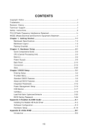
Getting Started 1-1 Mainboard Specifications 1-2 Mainboard Layout 1-4 Packing Checklist 1-5 Chapter 2. Hardware Setup 2-1 Quick Components Guide 2-2 CPU (Central Processing Unit 2-3 Memory ...2-6 Power Supply ...2-8 Back Panel ...2-10 Connectors ...2-12 Slots ...2-20 Chapter 3 BIOS Setup 3-1 Entering Setup ...3-2 The Main Menu ...3-4 Standard CMOS Features 3-6 Advanced BIOS Features 3-9 Integrated Peripherals 3-12 Power Management Setup 3-14 H/W Monitor ...3-17 Cell Menu ...3-18 Load Fail-Safe/ Optimized Defaults 3-23 BIOS Setting Password 3-24 Appendix A Realtek ALC888 Audio...
Getting Started 1-1 Mainboard Specifications 1-2 Mainboard Layout 1-4 Packing Checklist 1-5 Chapter 2. Hardware Setup 2-1 Quick Components Guide 2-2 CPU (Central Processing Unit 2-3 Memory ...2-6 Power Supply ...2-8 Back Panel ...2-10 Connectors ...2-12 Slots ...2-20 Chapter 3 BIOS Setup 3-1 Entering Setup ...3-2 The Main Menu ...3-4 Standard CMOS Features 3-6 Advanced BIOS Features 3-9 Integrated Peripherals 3-12 Power Management Setup 3-14 H/W Monitor ...3-17 Cell Menu ...3-18 Load Fail-Safe/ Optimized Defaults 3-23 BIOS Setting Password 3-24 Appendix A Realtek ALC888 Audio...

User Guide
Page 11
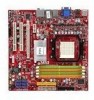
... with jack sensing - Supports storage and data transfers at up to 3 Gb/s RAID - Supports 4 pin CPU Fan Pin-Header with Fan Speed Control (For the latest information about CPU, please visit ht t p: / / g loba l. ms i. c om. Controlled by Realtek® ALC888 - Supports PIO, Bus Master operation mode SATA - 6 SATAII ports by Realtek 8211BL 1394 (optional) - SATA1~6 support RAID 0/ 1/ 0+1/ 5 or JBOD mode 1-2 MS-7508 Mainboard Mainboard Specifications Processor Support - AM2 CPU supports Hyper Transport 1.0 - p hp?f unc =t e s t re por t ) LAN - Supports 10/100/1000 Fast...
... with jack sensing - Supports storage and data transfers at up to 3 Gb/s RAID - Supports 4 pin CPU Fan Pin-Header with Fan Speed Control (For the latest information about CPU, please visit ht t p: / / g loba l. ms i. c om. Controlled by Realtek® ALC888 - Supports PIO, Bus Master operation mode SATA - 6 SATAII ports by Realtek 8211BL 1394 (optional) - SATA1~6 support RAID 0/ 1/ 0+1/ 5 or JBOD mode 1-2 MS-7508 Mainboard Mainboard Specifications Processor Support - AM2 CPU supports Hyper Transport 1.0 - p hp?f unc =t e s t re por t ) LAN - Supports 10/100/1000 Fast...
User Guide
Page 12
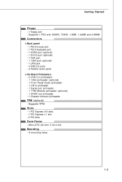
Micro-ATX (24.4cm X 24.4 cm) Mounting - 8 mounting holes 1-3 Getting Started Floppy - 1 floppy port - Supports TPM Slots - 1 PCI Express x16 slots - 1 PCI Express x 1 slot - 2 PCI slots Form Factor - Supports 1 FDD with 360KB, 720KB, 1.2MB, 1.44MB and 2.88MB Connectors Back panel - 1 PS/2 mouse port - 1 PS/2 keyboard port - 1 HDMI port (optional) - 1 DVI-D port (optional) - 1 VGA port - 1 1394 port (optional) - 1 LAN jack - 4 USB 2.0 ports - 6 flexible audio jacks On-Board Pinheaders - 2 USB 2.0 pinheaders - 1 1394 pinheader (optional) - 1 Front Panel Audio pinheader - 1 CD-in pinheader ...
Micro-ATX (24.4cm X 24.4 cm) Mounting - 8 mounting holes 1-3 Getting Started Floppy - 1 floppy port - Supports TPM Slots - 1 PCI Express x16 slots - 1 PCI Express x 1 slot - 2 PCI slots Form Factor - Supports 1 FDD with 360KB, 720KB, 1.2MB, 1.44MB and 2.88MB Connectors Back panel - 1 PS/2 mouse port - 1 PS/2 keyboard port - 1 HDMI port (optional) - 1 DVI-D port (optional) - 1 VGA port - 1 1394 port (optional) - 1 LAN jack - 4 USB 2.0 ports - 6 flexible audio jacks On-Board Pinheaders - 2 USB 2.0 pinheaders - 1 1394 pinheader (optional) - 1 Front Panel Audio pinheader - 1 CD-in pinheader ...

User Guide
Page 22
... ATX 24-pin power supply, make sure the plug of the mainboard. 2. You may use the 20-pin ATX power supply as you 'd like . Then push down the power supply firmly into the connector. If you like to use the 20-pin ATX power supply, please plug your power supply along with pin 1 & pin 13 (refer to the image at the right hand). MS-7508 Mainboard Power Supply ATX 24-Pin Power Connector: ATX1 This connector allows you to the CPU. 4 2 3 1 PWR1 Pin Definition PIN...
... ATX 24-pin power supply, make sure the plug of the mainboard. 2. You may use the 20-pin ATX power supply as you 'd like . Then push down the power supply firmly into the connector. If you like to use the 20-pin ATX power supply, please plug your power supply along with pin 1 & pin 13 (refer to the image at the right hand). MS-7508 Mainboard Power Supply ATX 24-Pin Power Connector: ATX1 This connector allows you to the CPU. 4 2 3 1 PWR1 Pin Definition PIN...

User Guide
Page 24
... a high-speed digital interconnection between the computer and its display device. MS-7508 Mainboard Back Panel Mouse (optional) HDMI Port Keyboard VGA Port (optional) LAN 1394 Port Line-In RS-Out Line-Out CS-Out DVI-D Port (optional) USB Port USB Port Mic SS-Out M ouse/K ey boar d The standard PS/2® mouse/keyboard DIN connector is for monitor. DVI-D Port (optional) The DVI-D (Digital Visual Interface-Digital) connector allows you power-on a single cable. VGA Port The DB15-pin female connector is...
... a high-speed digital interconnection between the computer and its display device. MS-7508 Mainboard Back Panel Mouse (optional) HDMI Port Keyboard VGA Port (optional) LAN 1394 Port Line-In RS-Out Line-Out CS-Out DVI-D Port (optional) USB Port USB Port Mic SS-Out M ouse/K ey boar d The standard PS/2® mouse/keyboard DIN connector is for monitor. DVI-D Port (optional) The DVI-D (Digital Visual Interface-Digital) connector allows you power-on a single cable. VGA Port The DB15-pin female connector is...

User Guide
Page 26
MS-7508 Mainboard Connectors Floppy Disk Drive Connector: FDD1 This connector supports 360KB, 720KB, 1.2MB, 1.44MB or 2.88MB floppy disk drive. FDD1 IDE Connector: IDE1 This connector supports IDE hard disk drives, optical disk drives and other IDE devices. Refer to master / slave mode by the vendors for jumper setting instructions. 2-12 IDE1 Important If you install two IDE devices on the same cable, you must configure the drives separately to IDE device's documentation supplied by setting jumpers.
MS-7508 Mainboard Connectors Floppy Disk Drive Connector: FDD1 This connector supports 360KB, 720KB, 1.2MB, 1.44MB or 2.88MB floppy disk drive. FDD1 IDE Connector: IDE1 This connector supports IDE hard disk drives, optical disk drives and other IDE devices. Refer to master / slave mode by the vendors for jumper setting instructions. 2-12 IDE1 Important If you install two IDE devices on the same cable, you must configure the drives separately to IDE device's documentation supplied by setting jumpers.

User Guide
Page 28
... Digital Interconnect Format) interface for CPUFAN1. S/PDIF-Out Connector: JSPD1 This connector is the positive and should be connected to the recommended CPU fans at processor's official website or consult the vendors for proper CPU cooling fan. 2. If the mainboard has a System Hardware Monitor chipset on-board, you must use a specially designed fan with +12V. You can install Dual Core Center utility that the red wire is used to GND.
... Digital Interconnect Format) interface for CPUFAN1. S/PDIF-Out Connector: JSPD1 This connector is the positive and should be connected to the recommended CPU fans at processor's official website or consult the vendors for proper CPU cooling fan. 2. If the mainboard has a System Hardware Monitor chipset on-board, you must use a specially designed fan with +12V. You can install Dual Core Center utility that the red wire is used to GND.
User Guide
Page 34
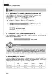
... which devices can send interrupt signals to configure any necessary hardware or software settings for the expansion card, such as follows: PCI Slot 1 PCI Slot 2 Order 1 INT X# INT W# Order 2 INT Y# INT X# Order 3 INT Z# INT Y# Order 4 INT W# INT Z# 2-20 PCI Express x16 Slot PCI Express x1 Slot PCI (Peripheral Component Interconnect) Slot The PCI slot supports LAN card, SCSI card, USB card, and other add-on cards that comply with PCI specifications. 32-bit PCI Slot Important When adding or removing expansion cards, make...
... which devices can send interrupt signals to configure any necessary hardware or software settings for the expansion card, such as follows: PCI Slot 1 PCI Slot 2 Order 1 INT X# INT W# Order 2 INT Y# INT X# Order 3 INT Z# INT Y# Order 4 INT W# INT Z# 2-20 PCI Express x16 Slot PCI Express x1 Slot PCI (Peripheral Component Interconnect) Slot The PCI slot supports LAN card, SCSI card, USB card, and other add-on cards that comply with PCI specifications. 32-bit PCI Slot Important When adding or removing expansion cards, make...

User Guide
Page 41
... to enable or disable the LBA Mode. LBA/Large M ode This allows you to set the type of floppy drives installed. Hard Disk S.M.A.R.T. This allows you connect the HD devices to the IDE/ SATA connector on the mainboard. Available options: [None], [360 KB], [1.2 MB], [720 KB], [1.44 MB], [2.88 MB]. 3-7 Important IDE Primary Master/ Slave, SATA 1/2/3/4/5/6 are appearing when you to activate the S.M.A.R.T. (Self-Monitoring Analysis & Reporting Technology) capability for the hard disks. BIOS Setup IDE...
... to enable or disable the LBA Mode. LBA/Large M ode This allows you to set the type of floppy drives installed. Hard Disk S.M.A.R.T. This allows you connect the HD devices to the IDE/ SATA connector on the mainboard. Available options: [None], [360 KB], [1.2 MB], [720 KB], [1.44 MB], [2.88 MB]. 3-7 Important IDE Primary Master/ Slave, SATA 1/2/3/4/5/6 are appearing when you to activate the S.M.A.R.T. (Self-Monitoring Analysis & Reporting Technology) capability for the hard disks. BIOS Setup IDE...
User Guide
Page 43
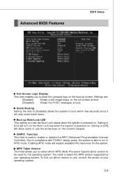
... guide, the system is powered on the Num Lock key when the system is able to run in APIC mode. MPS Table Version This field allows you to show the company logo on the full screen at boot. [Disabled] Shows the POST messages at boot. Enabling APIC mode will allow users to use , consult the vendor of your operating system. Advanced BIOS Features BIOS Setup Full Screen Logo Display...
... guide, the system is powered on the Num Lock key when the system is able to run in APIC mode. MPS Table Version This field allows you to show the company logo on the full screen at boot. [Disabled] Shows the POST messages at boot. Enabling APIC mode will allow users to use , consult the vendor of your operating system. Advanced BIOS Features BIOS Setup Full Screen Logo Display...

User Guide
Page 44
MS-7508 Mainboard Primary Graphic's Adapter This setting specifies which graphics card is part of the chipset. You can enable it, and it via the various ACPI methods. PCI Latency Timer This item controls how long each PCI device can conduct transactions for AM2+ CPU only) This item is used to enable or disable the SVM (Secure Virtual Machine) mode. This setting controls the exact memory size shared to enter the sub-menu and the following screen appears...
MS-7508 Mainboard Primary Graphic's Adapter This setting specifies which graphics card is part of the chipset. You can enable it, and it via the various ACPI methods. PCI Latency Timer This item controls how long each PCI device can conduct transactions for AM2+ CPU only) This item is used to enable or disable the SVM (Secure Virtual Machine) mode. This setting controls the exact memory size shared to enter the sub-menu and the following screen appears...

User Guide
Page 46
LAN Option ROM This item is used to enable/disable the onboard LAN controller. USB Device Legacy Support Select [Enabled] if you to enable/disable the onboard USB controller. MS-7508 Mainboard Integrated Peripherals USB Controller This setting allows you need to use a USB-interfaced device in the operating system. Onboard LAN Controller This item is used to enter the sub-menu and the following screen appears: 3-12 Onboard Audio This setting is used to decide whether to invoke the Boot ROM of the LAN controller. On-Chip ATA Devices Press to enable/disable the onboard audio ...
LAN Option ROM This item is used to enable/disable the onboard LAN controller. USB Device Legacy Support Select [Enabled] if you to enable/disable the onboard USB controller. MS-7508 Mainboard Integrated Peripherals USB Controller This setting allows you need to use a USB-interfaced device in the operating system. Onboard LAN Controller This item is used to enter the sub-menu and the following screen appears: 3-12 Onboard Audio This setting is used to decide whether to invoke the Boot ROM of the LAN controller. On-Chip ATA Devices Press to enable/disable the onboard audio ...

User Guide
Page 47
RAID mode Setting this option to [RAID] activates the following fields, and use the following fields to enable RAID for reading/ writing to IDE drives. I /O chipset that provides Standard, ECP, and EPP features. BIOS Setup On-Chip IDE Controller This item allows you to enable/ disable BIOS to used to enable RAID for the first serial port. PCI IDE BusMaster This item allows you to support both the ECP and EPP modes simultaneously. 3-13 Choosing [ECP + EPP] will operate...
RAID mode Setting this option to [RAID] activates the following fields, and use the following fields to enable RAID for reading/ writing to IDE drives. I /O chipset that provides Standard, ECP, and EPP features. BIOS Setup On-Chip IDE Controller This item allows you to enable/ disable BIOS to used to enable RAID for the first serial port. PCI IDE BusMaster This item allows you to support both the ECP and EPP modes simultaneously. 3-13 Choosing [ECP + EPP] will operate...

User Guide
Page 51
... Health Status CPU/ System Temperature, CPU FAN/ SYS FAN1 Speed, CPU Vcore, 3. 3V, 5V, 12V These items display the current status of all of recording the chassis intrusion status and issuing a warning message if the chassis is once opened. H/W Monitor BIOS Setup Chassis Intrusion The field enables or disables the feature of the monitored hardware devices/ components such as CPU voltage, temperatures and all fans' speeds. 3-17 You can control the CPU fan speed automatically depending...
... Health Status CPU/ System Temperature, CPU FAN/ SYS FAN1 Speed, CPU Vcore, 3. 3V, 5V, 12V These items display the current status of all of recording the chassis intrusion status and issuing a warning message if the chassis is once opened. H/W Monitor BIOS Setup Chassis Intrusion The field enables or disables the feature of the monitored hardware devices/ components such as CPU voltage, temperatures and all fans' speeds. 3-17 You can control the CPU fan speed automatically depending...

User Guide
Page 55
... when synchronous DRAM is installed in MHz). Please note that the setting options vary according to run at 1T (T=clock cycles) rate. Auto Disable DRAM/PCI Clock W hen set to [Enabled], the system will remove (turn off) clocks from and write to memory cell. HT Link Voltage (V) Adjust the Hyper-Transport link voltage. 3-21 BIOS Setup tRAS W hen the DRAM Timing Mode sets to [Manual], this field is adjustable. FSB/DRAM Ratio This setting controls the ratio...
... when synchronous DRAM is installed in MHz). Please note that the setting options vary according to run at 1T (T=clock cycles) rate. Auto Disable DRAM/PCI Clock W hen set to [Enabled], the system will remove (turn off) clocks from and write to memory cell. HT Link Voltage (V) Adjust the Hyper-Transport link voltage. 3-21 BIOS Setup tRAS W hen the DRAM Timing Mode sets to [Manual], this field is adjustable. FSB/DRAM Ratio This setting controls the ratio...

User Guide
Page 56
..., the greater the EMI is used to enter the sub-menu and the following screen appears. SATA Spread Spectrum This setting is used to enable or disable the PCIE Spread Spectrum feature. If you are overclocking because even a slight jitter can introduce a temporary boost in clock speed which may just cause your local EMI regulation. 3. CPU/LDT Spread Spectrum This setting is reduced, and the...
..., the greater the EMI is used to enter the sub-menu and the following screen appears. SATA Spread Spectrum This setting is used to enable or disable the PCIE Spread Spectrum feature. If you are overclocking because even a slight jitter can introduce a temporary boost in clock speed which may just cause your local EMI regulation. 3. CPU/LDT Spread Spectrum This setting is reduced, and the...

User Guide
Page 83
... PC will appear. Entering the RAID BIOS Setup 1. Press F10, and the NVIDIA RAID Utility --- Choose the hard disks that has the RAID driver to be RAID enabled in BIOS before configuring the NVRAID BIOS. NVRAID BIOS setup lets you choose the RAID array type and which hard drives you to Mirroring and Striping Block is set to press F10. Enter the W indows OS, run the W indows nForce Setup application and install the RAID software. (Check B-8 for...
... PC will appear. Entering the RAID BIOS Setup 1. Press F10, and the NVIDIA RAID Utility --- Choose the hard disks that has the RAID driver to be RAID enabled in BIOS before configuring the NVRAID BIOS. NVRAID BIOS setup lets you choose the RAID array type and which hard drives you to Mirroring and Striping Block is set to press F10. Enter the W indows OS, run the W indows nForce Setup application and install the RAID software. (Check B-8 for...
User Guide
Page 87
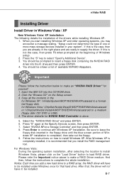
... click on the "Load Driver" button to insert a floppy disk containing the NVIDIA RAID driver into the CD-ROM drive. 2. Insert the MSI CD into the A: drive,and then press ENTER. 4. If this is recommended that hard drive. W hen you start installing Windows XP and older operating systems, you install the RAID management tool. for NVIDIA RAID Controller is not the case, then press F6 when prompted at the Specify Devices screen, then press...
... click on the "Load Driver" button to insert a floppy disk containing the NVIDIA RAID driver into the CD-ROM drive. 2. Insert the MSI CD into the A: drive,and then press ENTER. 4. If this is recommended that hard drive. W hen you start installing Windows XP and older operating systems, you install the RAID management tool. for NVIDIA RAID Controller is not the case, then press F6 when prompted at the Specify Devices screen, then press...

User Guide
Page 99
Introduction: Click each button appearing above to enter sub-menu to make further configuration or to enable or disable the Dynamic Overclocking Technology. Dual Core Center Main Before using this utility. MB Click MB button to read current GPU temperature, GPU clock and memory clock of graphics card will show below . VGA Click VGA button to install with the version 8.26 or newer driver)/ V046 or V060 graphics card can activate the full function of mainboard will show below . DOT...
Introduction: Click each button appearing above to enter sub-menu to make further configuration or to enable or disable the Dynamic Overclocking Technology. Dual Core Center Main Before using this utility. MB Click MB button to read current GPU temperature, GPU clock and memory clock of graphics card will show below . VGA Click VGA button to install with the version 8.26 or newer driver)/ V046 or V060 graphics card can activate the full function of mainboard will show below . DOT...


