
User Guide
Page 4
.... Notice 1 The changes or modifications not expressly approved by the party responsible for help. These limits are designed to operate the equipment. Micro-Star International MS-7250 This device complies with Part 15 of the FCC Rules. VOIR LANOTICE D'INSTALLATIONAVANT DE RACCORDER AU RESEAU. Operation is no guarantee that to correct the...
.... Notice 1 The changes or modifications not expressly approved by the party responsible for help. These limits are designed to operate the equipment. Micro-Star International MS-7250 This device complies with Part 15 of the FCC Rules. VOIR LANOTICE D'INSTALLATIONAVANT DE RACCORDER AU RESEAU. Operation is no guarantee that to correct the...
User Guide
Page 11
The K9N SLI/ K9N Ultra S eries mainboards are based on nVIDIA® nForce 570 SLI/ nForce 570 chipsets f or optimal system efficiency. Designed to fit the advanced AMD® Athlon 64 X2/ Athlon 64/ Athlon FX processor, the K9N SLI/ K9N Ultra Series deliver a high performance and professional desktop platform solution. 1-1 Getting Started Chapter 1 Getting Started Thank you for choosing the K9N SLI/ K9N Ultra Series (MS-7250 v2.X) ATX mainboard.
The K9N SLI/ K9N Ultra S eries mainboards are based on nVIDIA® nForce 570 SLI/ nForce 570 chipsets f or optimal system efficiency. Designed to fit the advanced AMD® Athlon 64 X2/ Athlon 64/ Athlon FX processor, the K9N SLI/ K9N Ultra Series deliver a high performance and professional desktop platform solution. 1-1 Getting Started Chapter 1 Getting Started Thank you for choosing the K9N SLI/ K9N Ultra Series (MS-7250 v2.X) ATX mainboard.
User Guide
Page 12
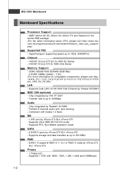
... Transfer rate is t . MS-7250 Mainboard Mainboard Specifications Processor Support - t w / pr og ra m/ p r od u c t s / ma in b oar d / mb d/ p ro_ mb d _c p u _s u pp ort . HyperTransport supporting speed up to 300 MB/s RAID - Chip integrated by nForce 570 SLI/ nForce 570 - Flexible 8-... Vitesse VSC8601 IEEE 1394 (optional) - c om. nVIDIA® nForce 570 for K9N SLI Series - AMD® Athlon 64 X2, Athlon 64, Athlon FX and Sempronin the socket AM2 package. (For the latest information about CPU, please visit http://www.msi. ms i . t w / pr og ra m/ p rod u c t s ...
... Transfer rate is t . MS-7250 Mainboard Mainboard Specifications Processor Support - t w / pr og ra m/ p r od u c t s / ma in b oar d / mb d/ p ro_ mb d _c p u _s u pp ort . HyperTransport supporting speed up to 300 MB/s RAID - Chip integrated by nForce 570 SLI/ nForce 570 - Flexible 8-... Vitesse VSC8601 IEEE 1394 (optional) - c om. nVIDIA® nForce 570 for K9N SLI Series - AMD® Athlon 64 X2, Athlon 64, Athlon FX and Sempronin the socket AM2 package. (For the latest information about CPU, please visit http://www.msi. ms i . t w / pr og ra m/ p rod u c t s ...
User Guide
Page 14
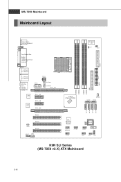
... W inb o nd I/O JCI1 JIR 1 D I MM 3 D I MM 4 D I MM 1 D I n M :L in e -O u t B: Mi c T:RS-Out M :C S- FD D1 MS-7250 Mainboard Mainboard Layout Top : mouse Bottom: keyboar d Top : Parallel Port Bottom: COM A 1394 Port (optional) S PD IF_ o ut (coax ial) T: LAN jack B: USB ports T: LAN... jack B: USB ports T:Line-I MM 2 IDE1 PW R 1 n vi di a nForce 570 SLI SATA5 NBFAN1 SATA 6 S ATA1 S ATA2 S ATA3 S ATA4 VI A VT6307 ( op t io n a l ) J 1 3 94 _ 1 (optional ) JUS B2 JUSB 3 SW2 BIOS JUS B1 B AT T + JDB1 JFP2 JFP1 K9N SLI Series (MS-7250 v2.X) ATX Mainboard 1-4
... W inb o nd I/O JCI1 JIR 1 D I MM 3 D I MM 4 D I MM 1 D I n M :L in e -O u t B: Mi c T:RS-Out M :C S- FD D1 MS-7250 Mainboard Mainboard Layout Top : mouse Bottom: keyboar d Top : Parallel Port Bottom: COM A 1394 Port (optional) S PD IF_ o ut (coax ial) T: LAN jack B: USB ports T: LAN... jack B: USB ports T:Line-I MM 2 IDE1 PW R 1 n vi di a nForce 570 SLI SATA5 NBFAN1 SATA 6 S ATA1 S ATA2 S ATA3 S ATA4 VI A VT6307 ( op t io n a l ) J 1 3 94 _ 1 (optional ) JUS B2 JUSB 3 SW2 BIOS JUS B1 B AT T + JDB1 JFP2 JFP1 K9N SLI Series (MS-7250 v2.X) ATX Mainboard 1-4
User Guide
Page 16
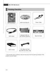
MS-7250 Mainboard Packing Checklist MSI motherboard MSI Driver/Utility CD Power Cable SATA Cable Standard Cable for IDE Devices (optional) Back IO Shield User's Guide SLI Video Link Card (for K9N SLI series only) * The pictures are for reference only and may vary from the packing contents of the product you purchased. 1-6
MS-7250 Mainboard Packing Checklist MSI motherboard MSI Driver/Utility CD Power Cable SATA Cable Standard Cable for IDE Devices (optional) Back IO Shield User's Guide SLI Video Link Card (for K9N SLI series only) * The pictures are for reference only and may vary from the packing contents of the product you purchased. 1-6
User Guide
Page 18
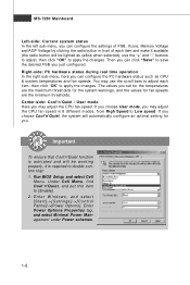
MS-7250 Mainboard Left-side: Current system status In the left sub-menu, you can configure the settings of FSB, Vcore, Memory Voltage and AGP Voltage by ...
MS-7250 Mainboard Left-side: Current system status In the left sub-menu, you can configure the settings of FSB, Vcore, Memory Voltage and AGP Voltage by ...

User Guide
Page 20
MS-7250 Mainboard Quick Components Guide Back Panel I / O, p.2-10 PWR2, p.2-8 CPU, p.2-3 CPUFAN1, SYSFAN1, p.2-14 p.2-14 PWR3, p.2-8 DDRII DIMMs, p.2-6 JIR1, p.2-15 JCI1, p.2-14 FDD1, p.2-12 PWR1, p.2-8 PCIE Slots, p.2-21 PCI Slots, p.2-24 IDE1, p.2-12 NBFAN1, p.2-14 SATA1~6, p.2-13 SW2, p.2-20 JAUD1, p.2-15 JFP1, p.2-18 JCD1, p.2-14 JFP2, p.2-18 JDB1, p.2-19 JUSB1~3, p.2-16 J1394_1 (optional), p.2-17 * The picture above is for K9N SLI series. 2-2
MS-7250 Mainboard Quick Components Guide Back Panel I / O, p.2-10 PWR2, p.2-8 CPU, p.2-3 CPUFAN1, SYSFAN1, p.2-14 p.2-14 PWR3, p.2-8 DDRII DIMMs, p.2-6 JIR1, p.2-15 JCI1, p.2-14 FDD1, p.2-12 PWR1, p.2-8 PCIE Slots, p.2-21 PCI Slots, p.2-24 IDE1, p.2-12 NBFAN1, p.2-14 SATA1~6, p.2-13 SW2, p.2-20 JAUD1, p.2-15 JFP1, p.2-18 JCD1, p.2-14 JFP2, p.2-18 JDB1, p.2-19 JUSB1~3, p.2-16 J1394_1 (optional), p.2-17 * The picture above is for K9N SLI series. 2-2

User Guide
Page 22
... sure to raise the lever up to a 90-degree angle. Press the CPU down firmly into the socket and close the lever with your mainboard. MS-7250 Mainboard CPU Installation Procedures for the gold arrow of the CPU to make sure the CPU is properly and completely embedded into the socket. 2-4 Please...
... sure to raise the lever up to a 90-degree angle. Press the CPU down firmly into the socket and close the lever with your mainboard. MS-7250 Mainboard CPU Installation Procedures for the gold arrow of the CPU to make sure the CPU is properly and completely embedded into the socket. 2-4 Please...

User Guide
Page 24
ph p DDRII 240-pin, 1.8V 56x2=112 pin 64x2=128 pin Dual-Channel Memory Population Rules 1 DIMM3 DIMM4 DIMM1 DIMM2 2 DIMM3 DIMM4 DIMM1 DIMM2 3 DIMM3 DIMM4 DIMM1 DIMM2 2-6 MS-7250 Mainboard Memory The mainboard provides four 240-pin non-ECC DDRII DIMMs and supports up to 8GB system memory. For more information on compatible components, please visit http://www.msi.com.tw/ p ro gr a m/ pr o du c t s /m ain bo ar d /m bd / pr o_ m bd _t r p_ lis t.
ph p DDRII 240-pin, 1.8V 56x2=112 pin 64x2=128 pin Dual-Channel Memory Population Rules 1 DIMM3 DIMM4 DIMM1 DIMM2 2 DIMM3 DIMM4 DIMM1 DIMM2 3 DIMM3 DIMM4 DIMM1 DIMM2 2-6 MS-7250 Mainboard Memory The mainboard provides four 240-pin non-ECC DDRII DIMMs and supports up to 8GB system memory. For more information on compatible components, please visit http://www.msi.com.tw/ p ro gr a m/ pr o du c t s /m ain bo ar d /m bd / pr o_ m bd _t r p_ lis t.
User Guide
Page 26
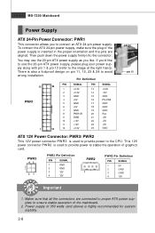
... at the right hand). Power supply of the power supply is highly recommended for system stability. 2-8 There is used to provide power to connect an ATX 24-pin power supply. If you to the CPU. Pin Definition 12 PWR1 1 24 PIN SIGNAL 1 +3.3V 2 +3.3V. 3 GND 4 +5V 5 GND 6 +5V 7... Power Connector: PWR3/ PWR2 This 12V power connector PW R3 is used to provide power to avoid wrong installation. MS-7250 Mainboard Power Supply ATX 24-Pin Power Connector: PWR1 This connector allows you 'd like . PWR3 42 31 PWR3 Pin Definition PIN SIGNAL 1 GND 2 GND 3 12V 4 ...
... at the right hand). Power supply of the power supply is highly recommended for system stability. 2-8 There is used to provide power to connect an ATX 24-pin power supply. If you to the CPU. Pin Definition 12 PWR1 1 24 PIN SIGNAL 1 +3.3V 2 +3.3V. 3 GND 4 +5V 5 GND 6 +5V 7... Power Connector: PWR3/ PWR2 This 12V power connector PW R3 is used to provide power to avoid wrong installation. MS-7250 Mainboard Power Supply ATX 24-Pin Power Connector: PWR1 This connector allows you 'd like . PWR3 42 31 PWR3 Pin Definition PIN SIGNAL 1 GND 2 GND 3 12V 4 ...

User Guide
Page 28
... high speed communications port that supports Enhanced Parallel Port (EPP) and Extended Capabilities Parallel Port (ECP) mode. You can connect a network cable to it. 2-10 MS-7250 Mainboard Back Panel Mouse Parallel Port LAN LAN L-In RS-Out Keyboard Serial Port 1394 S/PDIFPort Out (optional) USB Ports L-Out CS-Out Mic S/PDIFOut...
... high speed communications port that supports Enhanced Parallel Port (EPP) and Extended Capabilities Parallel Port (ECP) mode. You can connect a network cable to it. 2-10 MS-7250 Mainboard Back Panel Mouse Parallel Port LAN LAN L-In RS-Out Keyboard Serial Port 1394 S/PDIFPort Out (optional) USB Ports L-Out CS-Out Mic S/PDIFOut...

User Guide
Page 30
MS-7250 Mainboard Connectors Floppy Disk Drive Connector: FDD1 This standard FDD connector supports 360K, 720K, 1.2M, 1.44M and 2.88M floppy disk types. You can connect a Master ...
MS-7250 Mainboard Connectors Floppy Disk Drive Connector: FDD1 This standard FDD connector supports 360K, 720K, 1.2M, 1.44M and 2.88M floppy disk types. You can connect a Master ...
User Guide
Page 32
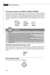
MS-7250 Mainboard Fan Power Connectors: CPUFAN1, SYSFAN1 & NBFAN1 The fan power connectors support system cooling fan with speed sensor to take note that the red wire ...
MS-7250 Mainboard Fan Power Connectors: CPUFAN1, SYSFAN1 & NBFAN1 The fan power connectors support system cooling fan with speed sensor to take note that the red wire ...

User Guide
Page 34
MS-7250 Mainboard Front USB Connectors: JUSB1, JUSB2 & JUSB3 The mainboard provides USB 2.0 pinheaders (optional USB 2.0 bracket available) that the pins of VCC and GND must be ...
MS-7250 Mainboard Front USB Connectors: JUSB1, JUSB2 & JUSB3 The mainboard provides USB 2.0 pinheaders (optional USB 2.0 bracket available) that the pins of VCC and GND must be ...

User Guide
Page 36
... LED JFP2 Pin Definition PIN SIGNAL 1 GND 2 SPK- 3 SLED 4 BUZ+ 5 PLED 6 BUZ- 7 NC 8 SPK+ DESCRIPTION Ground SpeakerSuspend LED Buzzer+ Power LED BuzzerNo connection Speaker+ 2-18 MS-7250 Mainboard Front Panel Connectors: JFP1/JFP2 The mainboard provides two front panel connectors for electrical connection to GND Reserved. HDD 1 +LED JFP1 Pin Definition PIN...
... LED JFP2 Pin Definition PIN SIGNAL 1 GND 2 SPK- 3 SLED 4 BUZ+ 5 PLED 6 BUZ- 7 NC 8 SPK+ DESCRIPTION Ground SpeakerSuspend LED Buzzer+ Power LED BuzzerNo connection Speaker+ 2-18 MS-7250 Mainboard Front Panel Connectors: JFP1/JFP2 The mainboard provides two front panel connectors for electrical connection to GND Reserved. HDD 1 +LED JFP1 Pin Definition PIN...
User Guide
Page 38
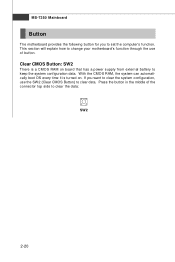
MS-7250 Mainboard Button The motherboard provides the following button for you want to clear the system configuration, use of the connector top side to keep the system configuration data. With ... is a CMOS RAM on . If you to clear data. Press the button in the middle of button. This section will explain how to change your motherboard's function through the use the SW 2 (Clear CMOS Button) to set the computer's function. Clear CMOS Button: SW2 There is turned on board that has...
MS-7250 Mainboard Button The motherboard provides the following button for you want to clear the system configuration, use of the connector top side to keep the system configuration data. With ... is a CMOS RAM on . If you to clear data. Press the button in the middle of button. This section will explain how to change your motherboard's function through the use the SW 2 (Clear CMOS Button) to set the computer's function. Clear CMOS Button: SW2 There is turned on board that has...
User Guide
Page 40
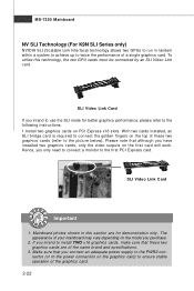
...the graphics card. 2-22 Please note that although you purchase. 2. SLI Video Link Card If you only need to connect a monitor to the picture below). MS-7250 Mainboard NV SLI Technology (For K9N SLI Series only) NVIDIA SLI (Scalable Link Interface) technology allows two GPUs to run in this ...technology, the two GPU cards must be connected by an SLI Video Link card. To utilize this section ...
...the graphics card. 2-22 Please note that although you purchase. 2. SLI Video Link Card If you only need to connect a monitor to the picture below). MS-7250 Mainboard NV SLI Technology (For K9N SLI Series only) NVIDIA SLI (Scalable Link Interface) technology allows two GPUs to run in this ...technology, the two GPU cards must be connected by an SLI Video Link card. To utilize this section ...

User Guide
Page 42
... as follows: PCI Slot 1 PCI Slot 2 PCI Slot 3 Order 1 INT E# INT F# INT G# Order 2 INT F# INT G# INT H# Order 3 INT G# INT H# INT E# Order 4 INT H# INT E# INT F# 2-24 MS-7250 Mainboard PCI (Peripheral Component Interconnect) Slots The PCI slots support LAN cards, SCSI cards, USB cards, and other add-on cards that comply with PCI...
... as follows: PCI Slot 1 PCI Slot 2 PCI Slot 3 Order 1 INT E# INT F# INT G# Order 2 INT F# INT G# INT H# Order 3 INT G# INT H# INT E# Order 4 INT H# INT E# INT F# 2-24 MS-7250 Mainboard PCI (Peripheral Component Interconnect) Slots The PCI slots support LAN cards, SCSI cards, USB cards, and other add-on cards that comply with PCI...
User Guide
Page 44
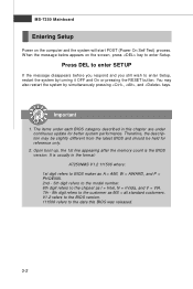
... was released. 3-2 V1.2 refers to the BIOS version. 111506 refers to the date this chapter are under continuous update for reference only. 2. MS-7250 Mainboard Entering Setup Power on the screen, press key to enter Setup. It is the BIOS version. The items under each BIOS category described in... the model number. 6th digit refers to the chipset as I = Intel, N = nVidia, and V = VIA. 7th - 8th digit refers to the customer as MS = all standard customers. You may be slightly different from the latest BIOS and should be held for better system performance. W hen the message below appears...
... was released. 3-2 V1.2 refers to the BIOS version. 111506 refers to the date this chapter are under continuous update for reference only. 2. MS-7250 Mainboard Entering Setup Power on the screen, press key to enter Setup. It is the BIOS version. The items under each BIOS category described in... the model number. 6th digit refers to the chipset as I = Intel, N = nVidia, and V = VIA. 7th - 8th digit refers to the customer as MS = all standard customers. You may be slightly different from the latest BIOS and should be held for better system performance. W hen the message below appears...
User Guide
Page 46
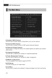
..., such as time, date etc. PNP/PCI Configurations This entry appears if your PC health status. H/W Monitor This entry shows your system supports PnP/PCI. MS-7250 Mainboard The Main Menu Standard CMOS Features Use this menu to specify your settings for power management. Integrated Peripherals Use this menu to specify your...
..., such as time, date etc. PNP/PCI Configurations This entry appears if your PC health status. H/W Monitor This entry shows your system supports PnP/PCI. MS-7250 Mainboard The Main Menu Standard CMOS Features Use this menu to specify your settings for power management. Integrated Peripherals Use this menu to specify your...


