
User Guide
Page 8
... 2-5 Memory ...2-6 Dual-Channel Memory Population Rules 2-6 Installing DDRII Modules 2-7 Power Supply ...2-8 ATX 24-Pin Power Connector: PWR1 2-8 ATX 12V Power Connector: PWR3/ PWR2 2-8 Important Notification about Power Issue 2-9 Back Panel ...2-10 Connectors ...2-12 Floppy Disk Drive Connector: FDD1 2-12 ATA133 Hard Disk Connectors: IDE1...: CPUFAN1, SYSFAN1 & NBFAN1 2-14 Chassis Intrusion Switch Connector: JCI1 2-14 CD-In Connector: JCD1 2-14 Front Panel Audio Connector: JAUD1 2-15 IrDA Infrared Module Header: JIR1 2-15 Front USB Connectors: JUSB1, JUSB2 & JUSB3 2-16 Front...
... 2-5 Memory ...2-6 Dual-Channel Memory Population Rules 2-6 Installing DDRII Modules 2-7 Power Supply ...2-8 ATX 24-Pin Power Connector: PWR1 2-8 ATX 12V Power Connector: PWR3/ PWR2 2-8 Important Notification about Power Issue 2-9 Back Panel ...2-10 Connectors ...2-12 Floppy Disk Drive Connector: FDD1 2-12 ATA133 Hard Disk Connectors: IDE1...: CPUFAN1, SYSFAN1 & NBFAN1 2-14 Chassis Intrusion Switch Connector: JCI1 2-14 CD-In Connector: JCD1 2-14 Front Panel Audio Connector: JAUD1 2-15 IrDA Infrared Module Header: JIR1 2-15 Front USB Connectors: JUSB1, JUSB2 & JUSB3 2-16 Front...

User Guide
Page 13
... Express x 1 slots - 3 PCI slots, support 3.3V/ 5V PCI bus Interface, includes one orange slot which supports 2 master for MSI special PCI function card (ex. wireless LAN and bluetooth combo card.). Getting Started Connectors Back panel - 1 PS/2 mouse port - 1 PS/2 keyboard port. - 1 serial port - 1 parallel port supporting SPP/EPP/ECP mode - 4 USB 2.0 Ports...
... Express x 1 slots - 3 PCI slots, support 3.3V/ 5V PCI bus Interface, includes one orange slot which supports 2 master for MSI special PCI function card (ex. wireless LAN and bluetooth combo card.). Getting Started Connectors Back panel - 1 PS/2 mouse port - 1 PS/2 keyboard port. - 1 serial port - 1 parallel port supporting SPP/EPP/ECP mode - 4 USB 2.0 Ports...
User Guide
Page 27
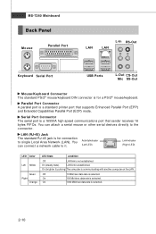
... Connector A parallel port is selected. You can attach a serial mouse or other serial devices directly to single Local Area Network (LAN). MS-7260 Mainboard Back Panel Mouse Parallel Port LAN LAN L-In RS-Out Keyboard Serial Port USB Ports L-Out CS-Out Mic SS-Out Mouse/Keyboard Connector The standard PS...
... Connector A parallel port is selected. You can attach a serial mouse or other serial devices directly to single Local Area Network (LAN). MS-7260 Mainboard Back Panel Mouse Parallel Port LAN LAN L-In RS-Out Keyboard Serial Port USB Ports L-Out CS-Out Mic SS-Out Mouse/Keyboard Connector The standard PS...
User Guide
Page 32
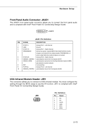
... 2 GND Ground 3 PORT 1R Analog Port 1 - signals BIOS that a High Definition Audio dongle is compliant with Intel® Front Panel I /O Connectivity Design Guide. 2 1 10 9 JAUD1 JAUD1 Pin Definition PIN SIGNAL DESCRIPTION 1 PORT 1L Analog Port 1 - You must... Pin Signal 1 NC 2 NC 3 VCC5 4 GND 5 IRTX 6 IRRX 2-15 Hardware Setup Front Panel Audio Connector: JAUD1 The JAUD1 front panel audio connector allows you to connect to connect the front panel audio and is connected to use the IR function. Right channel 4 PRESENCE# Active low signal - Left...
... 2 GND Ground 3 PORT 1R Analog Port 1 - signals BIOS that a High Definition Audio dongle is compliant with Intel® Front Panel I /O Connectivity Design Guide. 2 1 10 9 JAUD1 JAUD1 Pin Definition PIN SIGNAL DESCRIPTION 1 PORT 1L Analog Port 1 - You must... Pin Signal 1 NC 2 NC 3 VCC5 4 GND 5 IRTX 6 IRRX 2-15 Hardware Setup Front Panel Audio Connector: JAUD1 The JAUD1 front panel audio connector allows you to connect to connect the front panel audio and is connected to use the IR function. Right channel 4 PRESENCE# Active low signal - Left...

User Guide
Page 34
... reference pull-up Reset Switch high reference pull-up Power Switch low reference pull-down to the front panel switches and LEDs. Do not use. The JFP1 is compliant with Intel® Front Panel I/O Connectivity Design Guide. JFP2 +8 Speaker - + - 2 7 Power LED 1 JFP2 Pin Definition ...6 BUZ- 7 NC 8 SPK+ DESCRIPTION Ground SpeakerSuspend LED Buzzer+ Power LED BuzzerNo connection Speaker+ 2-17 Hardware Setup Front Panel Connectors: JFP1/JFP2 The mainboard provides two front panel connectors for electrical connection to GND Reserved. JFP1 10 Power Switch + Power LED 2 9 + Reset -
... reference pull-up Reset Switch high reference pull-up Power Switch low reference pull-down to the front panel switches and LEDs. Do not use. The JFP1 is compliant with Intel® Front Panel I/O Connectivity Design Guide. JFP2 +8 Speaker - + - 2 7 Power LED 1 JFP2 Pin Definition ...6 BUZ- 7 NC 8 SPK+ DESCRIPTION Ground SpeakerSuspend LED Buzzer+ Power LED BuzzerNo connection Speaker+ 2-17 Hardware Setup Front Panel Connectors: JFP1/JFP2 The mainboard provides two front panel connectors for electrical connection to GND Reserved. JFP1 10 Power Switch + Power LED 2 9 + Reset -
User Guide
Page 68
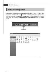
Click the audio icon from the Control Panel. It is also available to enable the audio driver by clicking the Azalia HD Sound Effect M anager from the system tray at the lower-right corner of the screen to use the 2-, 4-, 6- Double click A-4 channel audio feature now. or 8- MS-7260 Mainboard Software Configuration After installing the audio driver, you are able to activate the HD Audio Configuration.
Click the audio icon from the Control Panel. It is also available to enable the audio driver by clicking the Azalia HD Sound Effect M anager from the system tray at the lower-right corner of the screen to use the 2-, 4-, 6- Double click A-4 channel audio feature now. or 8- MS-7260 Mainboard Software Configuration After installing the audio driver, you are able to activate the HD Audio Configuration.

User Guide
Page 72
...MS-7260 Mainboard Mixer In the Mixer part, you may play different audio sources simultaneously and let them output respectively from the indicated real panel or front panel. The Realtek HD Audio front output item will appear. Click the button and the Mixer ToolBox menu will appear after you pluged in ...the jacks on the rear or front panel. Adjust Volume You can adjust the volume of the rear and front panels individually. 1. Then check the Enable playback multi-streaming and click OK to be plugged into the jacks...
...MS-7260 Mainboard Mixer In the Mixer part, you may play different audio sources simultaneously and let them output respectively from the indicated real panel or front panel. The Realtek HD Audio front output item will appear. Click the button and the Mixer ToolBox menu will appear after you pluged in ...the jacks on the rear or front panel. Adjust Volume You can adjust the volume of the rear and front panels individually. 1. Then check the Enable playback multi-streaming and click OK to be plugged into the jacks...

User Guide
Page 73
Then you are playing the first audio source (for example: use W indows Media Player to play DVD/VCD), the output will come out from the Line-Out audio jack of Front Panel. A-9 You will find that the second audio source (MP3 music) will be played from the rear panel, which is the default setting. Realtek ALC883 Audio W hen you must to select the Realtek HD Audio front output from the scroll list first, and use a different program to play the second audio source (for example: use Winamp to play MP3 files).
Then you are playing the first audio source (for example: use W indows Media Player to play DVD/VCD), the output will come out from the Line-Out audio jack of Front Panel. A-9 You will find that the second audio source (MP3 music) will be played from the rear panel, which is the default setting. Realtek ALC883 Audio W hen you must to select the Realtek HD Audio front output from the scroll list first, and use a different program to play the second audio source (for example: use Winamp to play MP3 files).

User Guide
Page 74
... freely decide which volume control items to be able to have an audio chat with your friends via headphone (stream 1 from front panel) while still have maximum 2 streams operating simultaneously. Advanced controls - Playback control Tool Mute Playback device This function is to let you ...can have music (stream 2 from back panel) in play. Enable playback multi-streaming W ith this is to let you will be displayed. - Realtek HD Audio 2nd Output Mute You...
... freely decide which volume control items to be able to have an audio chat with your friends via headphone (stream 1 from front panel) while still have maximum 2 streams operating simultaneously. Advanced controls - Playback control Tool Mute Playback device This function is to let you ...can have music (stream 2 from back panel) in play. Enable playback multi-streaming W ith this is to let you will be displayed. - Realtek HD Audio 2nd Output Mute You...

User Guide
Page 77
Mute rear panel output when front headphone plugged in . Enable auto popup dialogue, when device has been plugged in Once this item to access connector settings. If so, please check this item checked, the dialog "Connected device" would not automatically pop up when device plugged in . Connector Settings Click to disable front panel jack detection. Please check if front jacks on front panel jacks? A-13 Realtek ALC883 Audio Disable front panel jack detection (option) Find no function on your system are so-called AC'97 jacks.
Mute rear panel output when front headphone plugged in . Enable auto popup dialogue, when device has been plugged in Once this item to access connector settings. If so, please check this item checked, the dialog "Connected device" would not automatically pop up when device plugged in . Connector Settings Click to disable front panel jack detection. Please check if front jacks on front panel jacks? A-13 Realtek ALC883 Audio Disable front panel jack detection (option) Find no function on your system are so-called AC'97 jacks.

User Guide
Page 82
... to the correct phone jacks in accordance with the setting in this mode) 6 Line Out (Side surround channels, but no functioning in software utility. Back Panel 1 4 2 5 3 6 1 Line In 2 Line Out (Front channels) 3 MIC 4 Line Out (Rear surround channels, but no functioning in this mode) 5 Line Out (Center and Subwoofer channel, but... mode properly in the software utility, connect your speakers to the following diagram and caption for the function of each phone jack on the back panel when 2-Channel Mode is selected.
... to the correct phone jacks in accordance with the setting in this mode) 6 Line Out (Side surround channels, but no functioning in software utility. Back Panel 1 4 2 5 3 6 1 Line In 2 Line Out (Front channels) 3 MIC 4 Line Out (Rear surround channels, but no functioning in this mode) 5 Line Out (Center and Subwoofer channel, but... mode properly in the software utility, connect your speakers to the following diagram and caption for the function of each phone jack on the back panel when 2-Channel Mode is selected.

User Guide
Page 83
Realtek ALC883 Audio n 4-Channel Mode for 4-Speaker Output Back Panel 1 4 2 5 3 6 4-Channel Analog Audio Output Description: Connect two speakers to back panel's front-channel Line Out connector and two speakers to the real-channel Line Out c onn ec tor. 1 Line In 2 Line Out (Front channels) 3 MIC 4 Line Out (Rear surround channels) 5 Line Out (Center and Subwoofer channel, but no functioning in this mode) 6 Line Out (Side surround channels, but no functioning in this mode) A-19
Realtek ALC883 Audio n 4-Channel Mode for 4-Speaker Output Back Panel 1 4 2 5 3 6 4-Channel Analog Audio Output Description: Connect two speakers to back panel's front-channel Line Out connector and two speakers to the real-channel Line Out c onn ec tor. 1 Line In 2 Line Out (Front channels) 3 MIC 4 Line Out (Rear surround channels) 5 Line Out (Center and Subwoofer channel, but no functioning in this mode) 6 Line Out (Side surround channels, but no functioning in this mode) A-19

User Guide
Page 84
MS-7260 Mainboard n 6-Channel Mode for 6-Speaker Output Back Panel 1 4 2 5 3 6 6-Channel Analog Audio Output Description: Connect two speakers to back panel's Line Out connector, two speakers to the rear-channel Line out connector and two speakers to the center/ subwoofer-channel Line Out c onn ec tor. 1 Line In 2 Line Out (Front channels) 3 MIC 4 Line Out (Rear surround channels) 5 Line Out (Center and Subwoofer channel) 6 Line Out (Side surround channels, but no functioning in this mode) A-20
MS-7260 Mainboard n 6-Channel Mode for 6-Speaker Output Back Panel 1 4 2 5 3 6 6-Channel Analog Audio Output Description: Connect two speakers to back panel's Line Out connector, two speakers to the rear-channel Line out connector and two speakers to the center/ subwoofer-channel Line Out c onn ec tor. 1 Line In 2 Line Out (Front channels) 3 MIC 4 Line Out (Rear surround channels) 5 Line Out (Center and Subwoofer channel) 6 Line Out (Side surround channels, but no functioning in this mode) A-20

User Guide
Page 85
A-21 Realtek ALC883 Audio n 8-Channel Mode for 8-Speaker Output 1 4 2 5 3 6 8-Channel Analog Audio Output 1 Side Surround Out (Side channels) 2 Line Out (Front channels) 3 MIC 4 Line Out (Rear surround channels) 5 Line Out (Center and Subwoofer channel) 6 Line Out (Side channels) Description: Connect two speakers to back panel's Line Out connector, two speakers to the rear-channel Line out connector, two speakers to the center/subwooferchannel Line Out connector and two speakers to the side-channel Line Out connector.
A-21 Realtek ALC883 Audio n 8-Channel Mode for 8-Speaker Output 1 4 2 5 3 6 8-Channel Analog Audio Output 1 Side Surround Out (Side channels) 2 Line Out (Front channels) 3 MIC 4 Line Out (Rear surround channels) 5 Line Out (Center and Subwoofer channel) 6 Line Out (Side channels) Description: Connect two speakers to back panel's Line Out connector, two speakers to the rear-channel Line out connector, two speakers to the center/subwooferchannel Line Out connector and two speakers to the side-channel Line Out connector.

User Guide
Page 95
... appears. Click Next. The disks listed depend on "Computer Management". 2. The Initialize and Convert Disk W izards appears. 3. Launch Computer Management by clicking "Start" --> "Settings" --> "Control Panel" then open the "Administrative Tools" folder and double click on how many arrays you have configured. 4. MS-7260 Mainboard Initializing and Using the Disk Array...
... appears. Click Next. The disks listed depend on "Computer Management". 2. The Initialize and Convert Disk W izards appears. 3. Launch Computer Management by clicking "Start" --> "Settings" --> "Control Panel" then open the "Administrative Tools" folder and double click on how many arrays you have configured. 4. MS-7260 Mainboard Initializing and Using the Disk Array...

