User Guide
Page 2
...Support If a problem arises with your system and no guarantee is given as to make changes without notice. func=faqIndex Contact our technical staff at: http://support.msi...msi.com.tw/index.php? PS/2 and OS®/2 are registered trademarks or trademarks of International Business Machines Corporation. Alternatively, please try the following help resources for FAQ, technical guide, BIOS updates, driver updates...STAR INTERNATIONAL. Visit the MSI website for further guidance. Copyright Notice The material in this document, but no solution can be obtained from the user's manual,...
...Support If a problem arises with your system and no guarantee is given as to make changes without notice. func=faqIndex Contact our technical staff at: http://support.msi...msi.com.tw/index.php? PS/2 and OS®/2 are registered trademarks or trademarks of International Business Machines Corporation. Alternatively, please try the following help resources for FAQ, technical guide, BIOS updates, driver updates...STAR INTERNATIONAL. Visit the MSI website for further guidance. Copyright Notice The material in this document, but no solution can be obtained from the user's manual,...
User Guide
Page 8
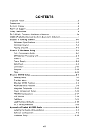
... Getting Started 1-1 Mainboard Specifications 1-2 Mainboard Layout 1-4 Packing Checklist 1-5 Chapter 2. Hardware Setup 2-1 Quick Components Guide 2-2 CPU (Central Processing Unit 2-3 Memory ...2-6 Power Supply ...2-8 Back Panel ...2-9 Connectors ...2-11 Jumpers ...2-18 Slots ...2-19 Chapter 3 BIOS Setup 3-1 Entering Setup ...3-2 The Main Menu ...3-4 Standard CMOS Features 3-6 Advanced BIOS Features 3-9 Integrated Peripherals 3-12 Power Management Setup 3-14 PNP/PCI Configurations 3-17 H/W Monitor ...3-19 Cell Menu ...3-20 Load Optimized Defaults 3-23 BIOS Setting Password 3-24...
... Getting Started 1-1 Mainboard Specifications 1-2 Mainboard Layout 1-4 Packing Checklist 1-5 Chapter 2. Hardware Setup 2-1 Quick Components Guide 2-2 CPU (Central Processing Unit 2-3 Memory ...2-6 Power Supply ...2-8 Back Panel ...2-9 Connectors ...2-11 Jumpers ...2-18 Slots ...2-19 Chapter 3 BIOS Setup 3-1 Entering Setup ...3-2 The Main Menu ...3-4 Standard CMOS Features 3-6 Advanced BIOS Features 3-9 Integrated Peripherals 3-12 Power Management Setup 3-14 PNP/PCI Configurations 3-17 H/W Monitor ...3-19 Cell Menu ...3-20 Load Optimized Defaults 3-23 BIOS Setting Password 3-24...

User Guide
Page 9
Appendix B AMD SATA RAID B-1 RAID Configuration B-2 Installing the RAID Driver (for bootable RAID Array B-8 Installing the RAID Driver Under W indows (for Non-bootable RAID Array) .... B-9 Appendix C Dual Core Center C-1 Activating Dual Core Center C-2 Main ...C-3 DOT(Dynamic Over Clocking C-5 Clock ...C-6 Voltage ...C-7 FAN Speed ...C-8 Temperature ...C-9 User Profile ...C-10 ix
Appendix B AMD SATA RAID B-1 RAID Configuration B-2 Installing the RAID Driver (for bootable RAID Array B-8 Installing the RAID Driver Under W indows (for Non-bootable RAID Array) .... B-9 Appendix C Dual Core Center C-1 Activating Dual Core Center C-2 Main ...C-3 DOT(Dynamic Over Clocking C-5 Clock ...C-6 Voltage ...C-7 FAN Speed ...C-8 Temperature ...C-9 User Profile ...C-10 ix
User Guide
Page 11
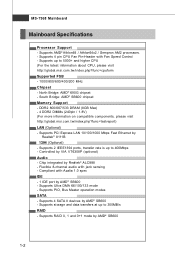
... CPU Fan Pin-Header with Fan Speed Control - t w / index. Supports PIO, Bus Master operation modes SATA - Supports storage and data transfers at up to 5000+ and higher CPU (For the latest information about CPU, please visit ht t p: / / g lobal . MS-7368 Mainboard Mainboard Specifications Processor Support - South Bridge: AMD® SB600 chipset Memory Support - t w / index. Supports 4 SATA II devices by AMD® SB600 1-2 php ?func =c puf orm Supported FSB - 1000/800/600/400/200 MHz Chipset - Controlled by Realtek® 8111B 1394 (Optional) - Supports PCI Express...
... CPU Fan Pin-Header with Fan Speed Control - t w / index. Supports PIO, Bus Master operation modes SATA - Supports storage and data transfers at up to 5000+ and higher CPU (For the latest information about CPU, please visit ht t p: / / g lobal . MS-7368 Mainboard Mainboard Specifications Processor Support - South Bridge: AMD® SB600 chipset Memory Support - t w / index. Supports 4 SATA II devices by AMD® SB600 1-2 php ?func =c puf orm Supported FSB - 1000/800/600/400/200 MHz Chipset - Controlled by Realtek® 8111B 1394 (Optional) - Supports PCI Express...

User Guide
Page 12
..., 1.2MB, 1.44MB and 2.88MB Connectors Back panel - 1 PS/2 mouse port - 1 PS/2 keyboard port - 1 HDMI port - 1 VGA port - 1 DVI port - 1 1394 port (optional) - 4 USB 2.0 Ports - 1 LAN jack - 6 flexible audio jacks On-Board Pinheaders - 3 USB 2.0 pinheaders - 1 1394 pinheader (optional) - 1 Front Panel Audio pinheader - 1 CD-in connector - 1 S/PDIF-Out pinheader (optional, for HDMI graphics card only) - 4 Serial ATA ports - 1 serial port pinheader Slots - 1 PCI Express x16 slot - 2 PCI Express x1 slots - 3 PCI slots Form Factor - Getting Started Floppy - 1 floppy port - ATX (30.5cm X 21.0 cm...
..., 1.2MB, 1.44MB and 2.88MB Connectors Back panel - 1 PS/2 mouse port - 1 PS/2 keyboard port - 1 HDMI port - 1 VGA port - 1 DVI port - 1 1394 port (optional) - 4 USB 2.0 Ports - 1 LAN jack - 6 flexible audio jacks On-Board Pinheaders - 3 USB 2.0 pinheaders - 1 1394 pinheader (optional) - 1 Front Panel Audio pinheader - 1 CD-in connector - 1 S/PDIF-Out pinheader (optional, for HDMI graphics card only) - 4 Serial ATA ports - 1 serial port pinheader Slots - 1 PCI Express x16 slot - 2 PCI Express x1 slots - 3 PCI slots Form Factor - Getting Started Floppy - 1 floppy port - ATX (30.5cm X 21.0 cm...

User Guide
Page 13
MS-7368 Mainboard Mainboard Layout Top: M ou se Bottom : Key board HDMI Port J1 J2 To p: VGA Port Bottom : DVI Port CPUFAN 1 To p: IEEE13 94 Port (optional) Bo ttom : USB Ports To p: LAN Jac k Bottom : USB Ports T:Line -In M :Line -O ut B:M ic T: RS-Out M: CS-Out B: SS-Out JPW1 SYSF AN1 AMD 690G DIMM2 DIMM1 DIMM4 DIMM3 ATX1 PCI _EX1 PCI _EX3 J C I1 JCD1 PCI _EX2 PCI1 PCI2 JAUD1 JSPD1 PCI3 JCOM...
MS-7368 Mainboard Mainboard Layout Top: M ou se Bottom : Key board HDMI Port J1 J2 To p: VGA Port Bottom : DVI Port CPUFAN 1 To p: IEEE13 94 Port (optional) Bo ttom : USB Ports To p: LAN Jac k Bottom : USB Ports T:Line -In M :Line -O ut B:M ic T: RS-Out M: CS-Out B: SS-Out JPW1 SYSF AN1 AMD 690G DIMM2 DIMM1 DIMM4 DIMM3 ATX1 PCI _EX1 PCI _EX3 J C I1 JCD1 PCI _EX2 PCI1 PCI2 JAUD1 JSPD1 PCI3 JCOM...
User Guide
Page 23
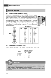
... Mainboard Power Supply ATX 24-Pin Power Connector: ATX1 This connector allows you like to use the 20-pin ATX power supply as you to the CPU. Power supply of 350 watts (and above) is also a foolproof design on pin 11, 12, 23 & 24 to avoid wrong installation. There is highly recommended for system stability. 2-8 ply along with pin 1 & pin 13 (refer to ensure stable operation of the power supply is used to provide power...
... Mainboard Power Supply ATX 24-Pin Power Connector: ATX1 This connector allows you like to use the 20-pin ATX power supply as you to the CPU. Power supply of 350 watts (and above) is also a foolproof design on pin 11, 12, 23 & 24 to avoid wrong installation. There is highly recommended for system stability. 2-8 ply along with pin 1 & pin 13 (refer to ensure stable operation of the power supply is used to provide power...

User Guide
Page 24
... computer is an all-digital audio/video interface capable of the cable is for more information.) 1394 Port (optional) The IEEE1394 port on the back panel provides connection to single Local Area Network (LAN). On 1000 Mbit/sec data rate is for monitor. It provides a high-speed digital interconnection between the computer and its display device. Hardware Setup Back Panel Mouse VGA Port 1394 Port (optional) LAN L-In RS-Out Keyboard HDMI Port DVI Port USB Ports L-Out CS-Out...
... computer is an all-digital audio/video interface capable of the cable is for more information.) 1394 Port (optional) The IEEE1394 port on the back panel provides connection to single Local Area Network (LAN). On 1000 Mbit/sec data rate is for monitor. It provides a high-speed digital interconnection between the computer and its display device. Hardware Setup Back Panel Mouse VGA Port 1394 Port (optional) LAN L-In RS-Out Keyboard HDMI Port DVI Port USB Ports L-Out CS-Out...

User Guide
Page 28
... the mainboard has a System Hardware Monitor chipset on-board, you to connect the front panel audio and is connected to GND. Please refer to take advantage of the CPU fan control. Left channel Ground Microphone - W hen connecting the wire to the connectors, always note that a HighDefinitionAudio dongle is compliant with speed sensor to the recommended CPU fans at AMD® official website or consult the vendors for proper CPU cooling fan. 3. PIN...
... the mainboard has a System Hardware Monitor chipset on-board, you to connect the front panel audio and is connected to GND. Please refer to take advantage of the CPU fan control. Left channel Ground Microphone - W hen connecting the wire to the connectors, always note that a HighDefinitionAudio dongle is compliant with speed sensor to the recommended CPU fans at AMD® official website or consult the vendors for proper CPU cooling fan. 3. PIN...

User Guide
Page 33
... J1 A1 B1 Enable the HDMI port. C1 J2 A1 B1 2-18 These jumpers allow you want to clear the system configuration, set the jumper to enable the deivce installed on it will damage the mainboard. If you to clear data. Avoid clearing the CMOS while the system is a CMOS RAM onboard that has a power supply from an external battery to 1-2 pin position. W ith the CMOS RAM, the system can clear CMOS by shorting 2-3 pin while the...
... J1 A1 B1 Enable the HDMI port. C1 J2 A1 B1 2-18 These jumpers allow you want to clear the system configuration, set the jumper to enable the deivce installed on it will damage the mainboard. If you to clear data. Avoid clearing the CMOS while the system is a CMOS RAM onboard that has a power supply from an external battery to 1-2 pin position. W ith the CMOS RAM, the system can clear CMOS by shorting 2-3 pin while the...

User Guide
Page 34
Hardware Setup Slots PCI (Peripheral Component Interconnect) Express Slot The PCI Express slot supports the PCI Express interface expansion card. PCI Express x1 Slot PCI Express x16 Slot PCI (Peripheral Component Interconnect) Slot The PCI slot supports LAN card, SCSI card, USB card, and other add-on cards that comply with PCI specifications. 32-bit PCI Slot Important When adding or removing expansion cards, make sure that you un plug the power supply first. The PCI Express x 1 slot supports up to 4.0 GB/s transfer rate. The PCI IRQ pins are hardware lines over which devices can send...
Hardware Setup Slots PCI (Peripheral Component Interconnect) Express Slot The PCI Express slot supports the PCI Express interface expansion card. PCI Express x1 Slot PCI Express x16 Slot PCI (Peripheral Component Interconnect) Slot The PCI slot supports LAN card, SCSI card, USB card, and other add-on cards that comply with PCI specifications. 32-bit PCI Slot Important When adding or removing expansion cards, make sure that you un plug the power supply first. The PCI Express x 1 slot supports up to 4.0 GB/s transfer rate. The PCI IRQ pins are hardware lines over which devices can send...

User Guide
Page 42
... IDE/ SATA connector on the mainboard. Read-only. Important IDE Primary Master/ Slave, SATA 1/2/3/4 are appearing when you to predict hard disk failure. Available options: [Disabled], [360 KB, 51/4"], [1.2 MB, 51/4"], [720 KB, 3 1/2"], [1.44 MB, 3 1/2"], [2.88 MB, 3 1/2"]. 3-7 This gives you to set the type of the floppy drives installed. DM A M ode This item allows you an opportunity to move data from a hard disk that monitors your disk status to enable or disable...
... IDE/ SATA connector on the mainboard. Read-only. Important IDE Primary Master/ Slave, SATA 1/2/3/4 are appearing when you to predict hard disk failure. Available options: [Disabled], [360 KB, 51/4"], [1.2 MB, 51/4"], [720 KB, 3 1/2"], [1.44 MB, 3 1/2"], [2.88 MB, 3 1/2"]. 3-7 This gives you to set the type of the floppy drives installed. DM A M ode This item allows you an opportunity to move data from a hard disk that monitors your disk status to enable or disable...

User Guide
Page 45
... Interrupt Controller). This setting controls the exact memory size shared to the onboard VGA card. Boot Sequence Press to enter the sub-menu and the following screen appears: HPET The HPET (High Precision Event Timers) is a component that is able to enable or disable the on-chip VGA function. Enabling APIC mode will provide you to run in APIC mode. Chipset Feature Press to it via the various ACPI methods. On-Chip VGA This setting...
... Interrupt Controller). This setting controls the exact memory size shared to the onboard VGA card. Boot Sequence Press to enter the sub-menu and the following screen appears: HPET The HPET (High Precision Event Timers) is a component that is able to enable or disable the on-chip VGA function. Enabling APIC mode will provide you to run in APIC mode. Chipset Feature Press to it via the various ACPI methods. On-Chip VGA This setting...

User Guide
Page 47
... onboard USB controller. MS-7368 Mainboard Integrated Peripherals USB Controller This setting allows you want to use any USB 1.1/2.0 device in the operating system that does not support or have any USB device other than the USB mouse. Set to [Disabled] only if you to invoke the Option ROM of the LAN controller. LAN Option ROM This item is used to decide whether to invoke the Boot ROM of the E-SATA controller. 3-12 USB Device Legacy Support Set to [Enabled] if you to use any USB 1.1/2.0 driver installed...
... onboard USB controller. MS-7368 Mainboard Integrated Peripherals USB Controller This setting allows you want to use any USB 1.1/2.0 device in the operating system that does not support or have any USB device other than the USB mouse. Set to [Disabled] only if you to invoke the Option ROM of the LAN controller. LAN Option ROM This item is used to decide whether to invoke the Boot ROM of the E-SATA controller. 3-12 USB Device Legacy Support Set to [Enabled] if you to use any USB 1.1/2.0 driver installed...

User Guide
Page 52
... PCI slot. 3-17 For better PCI performance, you should make any changes to higher values, every PCI device can conduct transactions for each PCI device can hold the bus before another takes over. BIOS Setup PNP/PCI Configurations This section describes configuring the PCI bus system and PnP (Plug & Play) feature. PCI, or Peripheral Component Interconnect, is a system which graphics card is strongly recommended that only experienced users should set to the default settings. PCI Slot...
... PCI slot. 3-17 For better PCI performance, you should make any changes to higher values, every PCI device can conduct transactions for each PCI device can hold the bus before another takes over. BIOS Setup PNP/PCI Configurations This section describes configuring the PCI bus system and PnP (Plug & Play) feature. PCI, or Peripheral Component Interconnect, is a system which graphics card is strongly recommended that only experienced users should set to the default settings. PCI Slot...

User Guide
Page 54
.... You can control the CPU fan speed automatically depending on the current temperature to keep it within a specific range. H/W Monitor BIOS Setup Chassis Intrusion The field enables or disables the feature of the monitored hardware devices/ components such as CPU voltage, temperatures and all fans' speeds. 3-19 CPU Smart FAN Target The mainboard provides the Smart Fan function which can select a fan target value here. If the current CPU fan temperature reaches to [Reset]. To clear the warning message, set the field...
.... You can control the CPU fan speed automatically depending on the current temperature to keep it within a specific range. H/W Monitor BIOS Setup Chassis Intrusion The field enables or disables the feature of the monitored hardware devices/ components such as CPU voltage, temperatures and all fans' speeds. 3-19 CPU Smart FAN Target The mainboard provides the Smart Fan function which can select a fan target value here. If the current CPU fan temperature reaches to [Reset]. To clear the warning message, set the field...

User Guide
Page 57
... even a slight jitter can increase the speed. Remember to disable Spread Spectrum if you are overclocking because even a slight jitter can introduce a temporary boost in clock speed which may just cause your local EMI regulation. 3. MS-7368 Mainboard FSB/Memory Ratio This setting control the ratio of CPU FSB / DRAM Clock Ratio to enable the CPU & DRAM to run at [Disabled] for EMI reduction. Important 1. The...
... even a slight jitter can increase the speed. Remember to disable Spread Spectrum if you are overclocking because even a slight jitter can introduce a temporary boost in clock speed which may just cause your local EMI regulation. 3. MS-7368 Mainboard FSB/Memory Ratio This setting control the ratio of CPU FSB / DRAM Clock Ratio to enable the CPU & DRAM to run at [Disabled] for EMI reduction. Important 1. The...
User Guide
Page 89
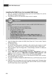
...-bit version or "AM D AHCI Compatible RAID Controller -x64 platform" when the system is formatted, and W indows setup starts copying files. B-8 For W indows Vista: During the Operating system installation, after the RAID volume is 64-bit version and then press ENTER. 8. W hen prompted, insert the floppy disk or media (Floppy, CD/DVD Or USB) and press Enter. 6. You should continue. 10. The next screen should confirm that contains the RAID driver,Press the "S" key...
...-bit version or "AM D AHCI Compatible RAID Controller -x64 platform" when the system is formatted, and W indows setup starts copying files. B-8 For W indows Vista: During the Operating system installation, after the RAID volume is 64-bit version and then press ENTER. 8. W hen prompted, insert the floppy disk or media (Floppy, CD/DVD Or USB) and press Enter. 6. You should continue. 10. The next screen should confirm that contains the RAID driver,Press the "S" key...
User Guide
Page 90
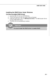
The driver will appear. 3. Important You must install the RAID driver to enable RAID. The CD will auto-run and the setup screen will be automatically installed. Insert the MSI CD into the CD-ROM drive. 2. AMD SATA RAID Installing the RAID Driver Under Windows (for Non-bootable RAID Array) 1. The AMD System Driver includes AMD RAID Driver. 4. Under the Driver tab, click on AMD System Driver. B-9
The driver will appear. 3. Important You must install the RAID driver to enable RAID. The CD will auto-run and the setup screen will be automatically installed. Insert the MSI CD into the CD-ROM drive. 2. AMD SATA RAID Installing the RAID Driver Under Windows (for Non-bootable RAID Array) 1. The AMD System Driver includes AMD RAID Driver. 4. Under the Driver tab, click on AMD System Driver. B-9

User Guide
Page 94
.... Dual Core Center Main Before using this utility. VGA Click VGA button to execute the function. If you : only when installing the MSI V044 (V044 has to enable or disable the Dynamic Overclocking Technology. Introduction: Click each button appearing above to enter sub-menu to make further configuration or to read current CPU temperature, FSB and CPU clock of graphics card will show below . C-3 MB Click MB button to read current GPU temperature, GPU clock and memory clock of mainboard...
.... Dual Core Center Main Before using this utility. VGA Click VGA button to execute the function. If you : only when installing the MSI V044 (V044 has to enable or disable the Dynamic Overclocking Technology. Introduction: Click each button appearing above to enter sub-menu to make further configuration or to read current CPU temperature, FSB and CPU clock of graphics card will show below . C-3 MB Click MB button to read current GPU temperature, GPU clock and memory clock of mainboard...
