User Guide
Page 1
Preface H81I H81I-S01 Motherboard G52-78511XD
Preface H81I H81I-S01 Motherboard G52-78511XD

User Guide
Page 11
... vi Battery Information vii Chemical Substances Information vii WEEE (Waste Electrical and Electronic Equipment) Statement viii Chapter 1 Getting Sarted 1-1 Packing Contents 1-2 Optional Accessories 1-2 Assembly Precautions 1-3 Motherboard Specifications 1-4 Connectors Quick Guide 1-6 Back Panel Quick Guide 1-8 CPU (Central Processing Unit 1-11 Introduction to the LGA 1150 CPU 1-11 CPU & Heatsink Installation 1-12 Memory...
... vi Battery Information vii Chemical Substances Information vii WEEE (Waste Electrical and Electronic Equipment) Statement viii Chapter 1 Getting Sarted 1-1 Packing Contents 1-2 Optional Accessories 1-2 Assembly Precautions 1-3 Motherboard Specifications 1-4 Connectors Quick Guide 1-6 Back Panel Quick Guide 1-8 CPU (Central Processing Unit 1-11 Introduction to the LGA 1150 CPU 1-11 CPU & Heatsink Installation 1-12 Memory...
User Guide
Page 12
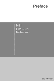
...: TPM Module Connector 1-25 Jumper 1-25 JBAT1: Clear CMOS Jumper 1-25 Drivers and Utilities 1-26 Total Installer 1-26 Chapter 2 Quick Installation 2-1 CPU Installation 2-2 Memory Installation 2-4 Motherboard Installation 2-5 Power Connectors Installation 2-7 SATA HDD Installation 2-9 mSATA SSD Installation 2-10 Front Panel Connector Installation 2-11 JFP1 Connector Installation 2-11 Front Panel Audio Connector Installation...
...: TPM Module Connector 1-25 Jumper 1-25 JBAT1: Clear CMOS Jumper 1-25 Drivers and Utilities 1-26 Total Installer 1-26 Chapter 2 Quick Installation 2-1 CPU Installation 2-2 Memory Installation 2-4 Motherboard Installation 2-5 Power Connectors Installation 2-7 SATA HDD Installation 2-9 mSATA SSD Installation 2-10 Front Panel Connector Installation 2-11 JFP1 Connector Installation 2-11 Front Panel Audio Connector Installation...

User Guide
Page 15
Designed to fit the advanced Intel® LGA1150 processor, the the H81I/ H81I-S01 series motherboards deliver a high performance and professional desktop platform solution. Chapter 1 Getting Started Thank you for optimal system efficiency. The the H81I/ H81I-S01 series motherboards are based on Intel® H81 chipset for choosing the H81I/ H81I-S01 series (MS-7851 v2.X) Mini-ITX motherboard.
Designed to fit the advanced Intel® LGA1150 processor, the the H81I/ H81I-S01 series motherboards deliver a high performance and professional desktop platform solution. Chapter 1 Getting Started Thank you for optimal system efficiency. The the H81I/ H81I-S01 series motherboards are based on Intel® H81 chipset for choosing the H81I/ H81I-S01 series (MS-7851 v2.X) Mini-ITX motherboard.

User Guide
Page 16
Getting Started 1-2 Chapter 1 Packing Contents Motherboard Drivers & Utilities Disc Motherboard User Guide I/O Shield SATA Cable Optional Accessories USB 3.0 Bracket M-Connector * These pictures are for reference only and may vary without notice. * The packing contents may vary according to the model you purchased. * If you need to purchase the optional accessories or request part numbers, please visit the MSI website at http://www.msi.com/index.php or consult the dealer.
Getting Started 1-2 Chapter 1 Packing Contents Motherboard Drivers & Utilities Disc Motherboard User Guide I/O Shield SATA Cable Optional Accessories USB 3.0 Bracket M-Connector * These pictures are for reference only and may vary without notice. * The packing contents may vary according to the model you purchased. * If you need to purchase the optional accessories or request part numbers, please visit the MSI website at http://www.msi.com/index.php or consult the dealer.

User Guide
Page 17
...edges to avoid touching sensitive components. ■ It is recommended to wear an electrostatic discharge (ESD) wrist strap when handling the motherboard to the user. ■ If you need help during any computer component. ■ Ensure that there are no loose screws ... to start. ■ Hold the motherboard by touching another metal object before handling the motherboard. ■ Store the motherboard in an electrostatic shielding container or on an antistatic pad whenever the motherboard is not installed. ■ Before turning on the motherboard or anywhere within the computer case. ...
...edges to avoid touching sensitive components. ■ It is recommended to wear an electrostatic discharge (ESD) wrist strap when handling the motherboard to the user. ■ If you need help during any computer component. ■ Ensure that there are no loose screws ... to start. ■ Hold the motherboard by touching another metal object before handling the motherboard. ■ Store the motherboard in an electrostatic shielding container or on an antistatic pad whenever the motherboard is not installed. ■ Before turning on the motherboard or anywhere within the computer case. ...

User Guide
Page 18
... the back panel, 4 ports available through the internal USB 2.0 connectors)** * For H81I only. ** For H81I-S01 only. ■ RENESAS UPD720202 chip - 2x USB 3.0 ports (2 ports on the back panel)* * For H81I only. ■ Realtek® ALC887 Codec - 7.1-Channel High Definition Audio - Chapter 1 Motherboard Specifications CPU Support Chipset Memory Support Expansion Slot Onboard Graphics Storage...
... the back panel, 4 ports available through the internal USB 2.0 connectors)** * For H81I only. ** For H81I-S01 only. ■ RENESAS UPD720202 chip - 2x USB 3.0 ports (2 ports on the back panel)* * For H81I only. ■ Realtek® ALC887 Codec - 7.1-Channel High Definition Audio - Chapter 1 Motherboard Specifications CPU Support Chipset Memory Support Expansion Slot Onboard Graphics Storage...

User Guide
Page 25
... make sure the cooling fans work properly to enhance heat dissipation. Notch Notch Chapter 1 Golden triangle is not recommend. MSI does not guarantee the damages or risks caused by inadequate operation beyond product specifications is the Pin 1 indicator Important Overheating ...Overheating can tolerate overclocking. Be sure to assist in correctly lining up the CPU for motherboard placement. Overclocking This motherboard is the Pin 1 indicator. CPU (Central Processing Unit) Introduction to the LGA 1150 CPU The surface of the ...
... make sure the cooling fans work properly to enhance heat dissipation. Notch Notch Chapter 1 Golden triangle is not recommend. MSI does not guarantee the damages or risks caused by inadequate operation beyond product specifications is the Pin 1 indicator Important Overheating ...Overheating can tolerate overclocking. Be sure to assist in correctly lining up the CPU for motherboard placement. Overclocking This motherboard is the Pin 1 indicator. CPU (Central Processing Unit) Introduction to the LGA 1150 CPU The surface of the ...

User Guide
Page 26
http://youtu.be/bf5La099urI 1. Wrong installation can damage both the CPU and the motherboard. Push the load lever down to unclip it and lift to prevent overheating and maintain system stability. The load plate will automatically lift up as ...
http://youtu.be/bf5La099urI 1. Wrong installation can damage both the CPU and the motherboard. Push the load lever down to unclip it and lift to prevent overheating and maintain system stability. The load plate will automatically lift up as ...

User Guide
Page 28
...CPU socket pins by covering the socket with the fan's cable facing towards the fan connector and the fasteners matching the holes on the motherboard. Motherboard Fastener-end Important • Confirm that the fastener-ends have been properly locked in the heatsink/ cooler package for more details about ...Finally, attach the CPU fan cable to the documentation in place. 11. CPU fan connector Chapter 1 9. 7. Place the heatsink on the motherboard with the plastic cap. • If you purchased a separate CPU and heatsink/ cooler, Please refer to the CPU fan connector on the...
...CPU socket pins by covering the socket with the fan's cable facing towards the fan connector and the fasteners matching the holes on the motherboard. Motherboard Fastener-end Important • Confirm that the fastener-ends have been properly locked in the heatsink/ cooler package for more details about ...Finally, attach the CPU fan cable to the documentation in place. 11. CPU fan connector Chapter 1 9. 7. Place the heatsink on the motherboard with the plastic cap. • If you purchased a separate CPU and heatsink/ cooler, Please refer to the CPU fan connector on the...

User Guide
Page 30
...came with the holes on the I /O ports should line up with the motherboard package. Chapter 1 The I /O backplate. Align the mounting plate's mounting stands with the screw holes on the motherboard and secure the motherboard with the screws provided with the computer case. The locations of the computer ...8226; To prevent damage to the manual that came with your computer case. For more information, please refer to the motherboard, any contact between the motherboard circuitry and the computer case, except for any screws. They should be facing toward the rear of the screw holes...
...came with the holes on the I /O ports should line up with the motherboard package. Chapter 1 The I /O backplate. Align the mounting plate's mounting stands with the screw holes on the motherboard and secure the motherboard with the screws provided with the computer case. The locations of the computer ...8226; To prevent damage to the manual that came with your computer case. For more information, please refer to the motherboard, any contact between the motherboard circuitry and the computer case, except for any screws. They should be facing toward the rear of the screw holes...

User Guide
Page 31
... power supply, align the power supply cable with the connector and firmly press the cable into the connector. If done correctly, the clip on the motherboard's power connector. 1.+23.+3.33.G4V.3.r+5Vo.5uG6Vn.r7+do.5uG8Vn.rP9do.Wu51nV0R1d.S1+O1B.1+K2211.V+3213.V+4.133.-5V.113.2G6V1V.rP7o1.SuG81-n.rO9Gdo2.NurG0o2n#.ruR1do2n...
... power supply, align the power supply cable with the connector and firmly press the cable into the connector. If done correctly, the clip on the motherboard's power connector. 1.+23.+3.33.G4V.3.r+5Vo.5uG6Vn.r7+do.5uG8Vn.rP9do.Wu51nV0R1d.S1+O1B.1+K2211.V+3213.V+4.133.-5V.113.2G6V1V.rP7o1.SuG81-n.rO9Gdo2.NurG0o2n#.ruR1do2n...

User Guide
Page 33
...lock. If needed, screw the edge of the graphics card to install a graphics card on the motherboard. Push the video card into its expansion slot(s). For best compatibility, MSI graphics cards are recommended. Depending on the expansion slot(s) used, there should be clip(s) on one... or more discrete video cards will significantly boost the system's graphics performance. http://youtu.be installed by way of the motherboard's expansion slots. Chapter 1...
...lock. If needed, screw the edge of the graphics card to install a graphics card on the motherboard. Push the video card into its expansion slot(s). For best compatibility, MSI graphics cards are recommended. Depending on the expansion slot(s) used, there should be clip(s) on one... or more discrete video cards will significantly boost the system's graphics performance. http://youtu.be installed by way of the motherboard's expansion slots. Chapter 1...

User Guide
Page 34
... how to the manual that large SATA devices, such as HDDs, SSDs, and optical drives, be screwed down into the case. Please refer to the motherboard for space saving purposes. Chapter 1 Internal Connectors SATA1~4: SATA Connectors This connector is recommended that the flat connector be connected to the device's manual for...
... how to the manual that large SATA devices, such as HDDs, SSDs, and optical drives, be screwed down into the case. Please refer to the motherboard for space saving purposes. Chapter 1 Internal Connectors SATA1~4: SATA Connectors This connector is recommended that the flat connector be connected to the device's manual for...

User Guide
Page 35
... Smart Fan Control with +12V. The Command Center utility can be activated. JCI1: Chassis Intrusion Connector This connector connects to the motherboard and will be plugged into any fan blades. If the computer case is opened, the chassis intrusion mechanism will instead connect to ...warning, you must enter the BIOS utility and clear the record. 2.C1.IGNTroRuUnd 1-21 Getting Started If the motherboard has a System Hardware Monitor chipset on the motherboard to the power supply directly. A system fan can be installed to automatically control the fan speeds according to ...
... Smart Fan Control with +12V. The Command Center utility can be activated. JCI1: Chassis Intrusion Connector This connector connects to the motherboard and will be plugged into any fan blades. If the computer case is opened, the chassis intrusion mechanism will instead connect to ...warning, you must enter the BIOS utility and clear the record. 2.C1.IGNTroRuUnd 1-21 Getting Started If the motherboard has a System Hardware Monitor chipset on the motherboard to the power supply directly. A system fan can be installed to automatically control the fan speeds according to ...
User Guide
Page 36
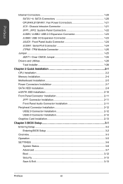
... small triangles are positive wires. The JFP1 connector is compliant with the Intel® Front Panel I/O Connectivity Design Guide. http://youtu.be plugged into the motherboard. Getting Started 1-22 Chapter 1 JFP1, JFP2: System Panel Connectors These connectors connect to determine correct connector orientation and placement. • The majority of the computer...
... small triangles are positive wires. The JFP1 connector is compliant with the Intel® Front Panel I/O Connectivity Design Guide. http://youtu.be plugged into the motherboard. Getting Started 1-22 Chapter 1 JFP1, JFP2: System Panel Connectors These connectors connect to determine correct connector orientation and placement. • The majority of the computer...

User Guide
Page 39
... clear the CMOS RAM. 1 Keep Data 1 Clear Data Important You can automatically boot into the operating system (OS) every time it will damage the motherboard. 1-25 Getting Started If you want to clear the system configuration, set the jumpers to save system configuration data. Chapter 1 JTPM1: TPM Module Connector This ...
... clear the CMOS RAM. 1 Keep Data 1 Clear Data Important You can automatically boot into the operating system (OS) every time it will damage the motherboard. 1-25 Getting Started If you want to clear the system configuration, set the jumpers to save system configuration data. Chapter 1 JTPM1: TPM Module Connector This ...

User Guide
Page 40
...the utilities. The software installation will automatically appear if autorun is very easy to use the same method to restart. 6. Getting Started 1-26 MSI motherboard comes with a Driver Disc. You can also use and does a great job of the new computer you just built. Chapter 1 Click ...dialog. 4. A popup dialogue will need to install drivers to utilize your computer from viruses by installing the bundled security program. Insert MSI Driver Disc into the optical drive. Drivers allow the computer to maximize the performance of finding necessary drivers. Please follow the steps ...
...the utilities. The software installation will automatically appear if autorun is very easy to use the same method to restart. 6. Getting Started 1-26 MSI motherboard comes with a Driver Disc. You can also use and does a great job of the new computer you just built. Chapter 1 Click ...dialog. 4. A popup dialogue will need to install drivers to utilize your computer from viruses by installing the bundled security program. Insert MSI Driver Disc into the optical drive. Drivers allow the computer to maximize the performance of finding necessary drivers. Please follow the steps ...

User Guide
Page 45
Motherboard Installation 1 Chapter 2 2 2-5 Quick Installation
Motherboard Installation 1 Chapter 2 2 2-5 Quick Installation

User Guide
Page 57
... disk. ■ OC PROFILE -This menu is used to set the speeds of fans and monitor voltages of the installed devices on the motherboard. It provides the information of system. ■ BOARD EXPLORER - Chapter 3 3-3 BIOS Setup Model name Virtual OC Genie Button Temperature monitor ... selection System information Boot device priority bar BIOS menu selection Menu display ▶ Temperature monitor Shows the temperatures of the processor and the motherboard. ▶ Language Allows you to select the language of the BIOS setup. ▶ System information Shows the time, date, CPU ...
... disk. ■ OC PROFILE -This menu is used to set the speeds of fans and monitor voltages of the installed devices on the motherboard. It provides the information of system. ■ BOARD EXPLORER - Chapter 3 3-3 BIOS Setup Model name Virtual OC Genie Button Temperature monitor ... selection System information Boot device priority bar BIOS menu selection Menu display ▶ Temperature monitor Shows the temperatures of the processor and the motherboard. ▶ Language Allows you to select the language of the BIOS setup. ▶ System information Shows the time, date, CPU ...


