
User Guide
Page 11
... Information vii WEEE (Waste Electrical and Electronic Equipment) Statement viii Chapter 1 Getting Sarted 1-1 Packing Contents 1-2 Optional Accessories 1-2 Assembly Precautions 1-3 Motherboard Specifications 1-4 Connectors Quick Guide 1-6 Back Panel Quick Guide 1-8 CPU (Central Processing Unit 1-11 Introduction to the LGA 1150 CPU 1-11 CPU & Heatsink Installation 1-12 Memory 1-15 Dual-Channel mode Population Rule...
... Information vii WEEE (Waste Electrical and Electronic Equipment) Statement viii Chapter 1 Getting Sarted 1-1 Packing Contents 1-2 Optional Accessories 1-2 Assembly Precautions 1-3 Motherboard Specifications 1-4 Connectors Quick Guide 1-6 Back Panel Quick Guide 1-8 CPU (Central Processing Unit 1-11 Introduction to the LGA 1150 CPU 1-11 CPU & Heatsink Installation 1-12 Memory 1-15 Dual-Channel mode Population Rule...
User Guide
Page 12
... 1-26 Chapter 2 Quick Installation 2-1 CPU Installation 2-2 Memory Installation 2-4 Motherboard Installation 2-5 Power Connectors Installation 2-7 SATA HDD Installation 2-9 mSATA SSD Installation 2-10 Front Panel Connector Installation 2-11 JFP1 Connector Installation 2-11 Front Panel Audio Connector Installation 2-11 Peripheral Connector Installation 2-12 USB2.0 Connector Installation 2-12 USB3.0 Connector Installation 2-12 Graphics Card Installation 2-13 Chapter...
... 1-26 Chapter 2 Quick Installation 2-1 CPU Installation 2-2 Memory Installation 2-4 Motherboard Installation 2-5 Power Connectors Installation 2-7 SATA HDD Installation 2-9 mSATA SSD Installation 2-10 Front Panel Connector Installation 2-11 JFP1 Connector Installation 2-11 Front Panel Audio Connector Installation 2-11 Peripheral Connector Installation 2-12 USB2.0 Connector Installation 2-12 USB3.0 Connector Installation 2-12 Graphics Card Installation 2-13 Chapter...

User Guide
Page 18
... Memory Support Expansion Slot Onboard Graphics Storage USB Audio LAN Back Panel Connectors ■ 4th Generation Intel® Core™ i7 / Core™ i5 / Core™ i3 / Pentium® / Celeron® processors for H81I) ■ 1x Optical S/PDIF-OUT connector ■ 1x ... connector) - 6x USB 2.0 ports (2 ports on the back panel, 4 ports available through the internal USB 2.0 connectors)* - 8x USB 2.0 ports (4 ports on the back panel, 4 ports available through the internal USB 2.0 connectors)** * For H81I only. ** For H81I-S01 only. ■ RENESAS UPD720202 chip - 2x USB 3.0 ports...
... Memory Support Expansion Slot Onboard Graphics Storage USB Audio LAN Back Panel Connectors ■ 4th Generation Intel® Core™ i7 / Core™ i5 / Core™ i3 / Pentium® / Celeron® processors for H81I) ■ 1x Optical S/PDIF-OUT connector ■ 1x ... connector) - 6x USB 2.0 ports (2 ports on the back panel, 4 ports available through the internal USB 2.0 connectors)* - 8x USB 2.0 ports (4 ports on the back panel, 4 ports available through the internal USB 2.0 connectors)** * For H81I only. ** For H81I-S01 only. ■ RENESAS UPD720202 chip - 2x USB 3.0 ports...

User Guide
Page 19
... 6.7 in . (17 cm x 17 cm) For the latest information about CPU, please visit http://www.msi.com/service/cpu-support/ For more information on compatible components, please visit http://www.msi.com/service/test-report/ 1-5 Getting Started Command Center - Live Update 5 - x 6.7 in . Super Charger...1x 4-pin CPU fan connector ■ 1x 4-pin system fan connector ■ 1x Clear CMOS jumper ■ 1x Front panel audio connector ■ 2x System panel connectors ■ 1x Serial port connector ■ 1x TPM connector ■ 1x Chassis Intrusion connector ■ NUVOTON NCT5533 Controller ...
... 6.7 in . (17 cm x 17 cm) For the latest information about CPU, please visit http://www.msi.com/service/cpu-support/ For more information on compatible components, please visit http://www.msi.com/service/test-report/ 1-5 Getting Started Command Center - Live Update 5 - x 6.7 in . Super Charger...1x 4-pin CPU fan connector ■ 1x 4-pin system fan connector ■ 1x Clear CMOS jumper ■ 1x Front panel audio connector ■ 2x System panel connectors ■ 1x Serial port connector ■ 1x TPM connector ■ 1x Chassis Intrusion connector ■ NUVOTON NCT5533 Controller ...

User Guide
Page 21
...~2 JTPM1 JUSB1/ JUSB2 JUSB3 PCI_E1 SATA1~4 Port Type I/O ports LGA1150 CPU Socket Fan Power Connectors DDR3 Memory Slots Front Panel Audio Connector Clear CMOS Jumper Chassis Intrusion Connector Serial Port Connector System Panel Connectors ATX Power Connectors TPM Module Connector USB 2.0 Expansion Connectors USB 3.0 Expansion Connector PCIe 2.0 Expansion Slot SATA Connectors Page...
...~2 JTPM1 JUSB1/ JUSB2 JUSB3 PCI_E1 SATA1~4 Port Type I/O ports LGA1150 CPU Socket Fan Power Connectors DDR3 Memory Slots Front Panel Audio Connector Clear CMOS Jumper Chassis Intrusion Connector Serial Port Connector System Panel Connectors ATX Power Connectors TPM Module Connector USB 2.0 Expansion Connectors USB 3.0 Expansion Connector PCIe 2.0 Expansion Slot SATA Connectors Page...
User Guide
Page 36
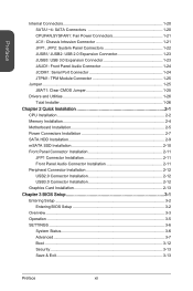
... computer case into the M-Connector and then plug the M-Connector into JFP1. The JFP1 connector is compliant with the Intel® Front Panel I/O Connectivity Design Guide. http://youtu.be plugged into the motherboard. Plug all the wires from the case, pins marked by small triangles... wires. Video Demonstration Watch the video to learn how to the front panel switches and LEDs. Chapter 1 JFP1, JFP2: System Panel Connectors These connectors connect to Install front panel connectors. When installing the front panel connectors, please use the diagrams above and the writing on the optional ...
... computer case into the M-Connector and then plug the M-Connector into JFP1. The JFP1 connector is compliant with the Intel® Front Panel I/O Connectivity Design Guide. http://youtu.be plugged into the motherboard. Plug all the wires from the case, pins marked by small triangles... wires. Video Demonstration Watch the video to learn how to the front panel switches and LEDs. Chapter 1 JFP1, JFP2: System Panel Connectors These connectors connect to Install front panel connectors. When installing the front panel connectors, please use the diagrams above and the writing on the optional ...

User Guide
Page 38
This connector is compliant with the Intel® Front Panel I/O Connectivity Design Guide. 2.G4r.oN6uC.Mn8d.1INC0o.DHPeeitnaedctPiohnone Detection 1.M3.IMC5.ILHC7e.RS9a.EdHNPeShaEodn_PeShERoNneDL JCOM1: Serial Port Connector This connector is a 16550A high speed communication port that sends/receives 16 bytes FIFOs. Chapter 1 JAUD1: Front Panel Audio Connector This connector allows you to connect the front audio panel located on your computer case. You can attach a serial device. 2.S4I.ND6T.DR8S1.C0RT.NSo Pin 1.D3.CS5DO.G7Ur.RTo9uT.RnSdI Getting Started 1-24
This connector is compliant with the Intel® Front Panel I/O Connectivity Design Guide. 2.G4r.oN6uC.Mn8d.1INC0o.DHPeeitnaedctPiohnone Detection 1.M3.IMC5.ILHC7e.RS9a.EdHNPeShaEodn_PeShERoNneDL JCOM1: Serial Port Connector This connector is a 16550A high speed communication port that sends/receives 16 bytes FIFOs. Chapter 1 JAUD1: Front Panel Audio Connector This connector allows you to connect the front audio panel located on your computer case. You can attach a serial device. 2.S4I.ND6T.DR8S1.C0RT.NSo Pin 1.D3.CS5DO.G7Ur.RTo9uT.RnSdI Getting Started 1-24

User Guide
Page 78
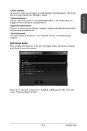
...enable the audio driver by clicking the Realtek HD Audio Manager from the Control Panel. Driver and Utilities), the "Realtek HD Audio Manager" icon will pop up accordingly. Software panel overview The following figure describes the function of the screen). Device Selection Application... Enhancement Volume Adjustment Realtek Audio A-2 Jack status panel You may double click the icon and the GUI will appear ...
...enable the audio driver by clicking the Realtek HD Audio Manager from the Control Panel. Driver and Utilities), the "Realtek HD Audio Manager" icon will pop up accordingly. Software panel overview The following figure describes the function of the screen). Device Selection Application... Enhancement Volume Adjustment Realtek Audio A-2 Jack status panel You may double click the icon and the GUI will appear ...
User Guide
Page 79
... the jack, a dialogue window will provide you a complete guidance of options will pop up asking you plugged in front or rear panel by adjust the bar. ▶ Application Enhancement The array of anticipated sound effect for both output and input device. ▶ Jack status... panel This panel depicts all render and capture devices currently connected with your computer. A-3 Realtek Audio The "check" sign (in orange) indicates the devices as default....
... the jack, a dialogue window will provide you a complete guidance of options will pop up asking you plugged in front or rear panel by adjust the bar. ▶ Application Enhancement The array of anticipated sound effect for both output and input device. ▶ Jack status... panel This panel depicts all render and capture devices currently connected with your computer. A-3 Realtek Audio The "check" sign (in orange) indicates the devices as default....

