User Guide
Page 2
...History Revision V2.0 Revision History First release for FAQ, technical guide, BIOS updates, driver updates, and other information: http://www.msi.com/service/download/ ◙ Contact our technical staff at: http://support.msi.com/ ii Alternatively, please try the following help resources for further ...guidance. ◙ Visit the MSI website for PCB 2.X Date 2011/04 Technical ...
...History Revision V2.0 Revision History First release for FAQ, technical guide, BIOS updates, driver updates, and other information: http://www.msi.com/service/download/ ◙ Contact our technical staff at: http://support.msi.com/ ii Alternatively, please try the following help resources for further ...guidance. ◙ Visit the MSI website for PCB 2.X Date 2011/04 Technical ...
User Guide
Page 8
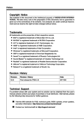
... 2-2 Screw Holes 2-3 CPU (Central Processing Unit 2-4 Memory 2-7 Power Supply 2-9 Back Panel 2-10 Connectors 2-12 Jumpers 2-18 Buttons 2-19 Slots 2-20 LED Status Indicators 2-21 Chapter 3 BIOS Setup 3-1 Entering Setup 3-2 The Menu Bar 3-4 Main Menu 3-5 Advanced 3-6 Overclocking 3-11 M-Flash 3-15 Security 3-16 Green Power 3-18 Boot 3-19 Save & Exit 3-20 viii
... 2-2 Screw Holes 2-3 CPU (Central Processing Unit 2-4 Memory 2-7 Power Supply 2-9 Back Panel 2-10 Connectors 2-12 Jumpers 2-18 Buttons 2-19 Slots 2-20 LED Status Indicators 2-21 Chapter 3 BIOS Setup 3-1 Entering Setup 3-2 The Menu Bar 3-4 Main Menu 3-5 Advanced 3-6 Overclocking 3-11 M-Flash 3-15 Security 3-16 Green Power 3-18 Boot 3-19 Save & Exit 3-20 viii

User Guide
Page 28
... message on the screen. Hardware Setup Connectors Serial ATA Connector: SATA1~6 This connector is for reference only. To clear the warning, you must enter the BIOS utility and clear the record. 1.C2.IGNTroRuUnd 2-12 Each connector can connect to the chassis intrusion switch cable. SATA1_2 SATA3_4 SATA5_6 SATA1~6 (6Gb/s) supported by...
... message on the screen. Hardware Setup Connectors Serial ATA Connector: SATA1~6 This connector is for reference only. To clear the warning, you must enter the BIOS utility and clear the record. 1.C2.IGNTroRuUnd 2-12 Each connector can connect to the chassis intrusion switch cable. SATA1_2 SATA3_4 SATA5_6 SATA1~6 (6Gb/s) supported by...
User Guide
Page 35
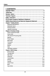
... the damages or risks caused by the OC Genie overclocking behavior. And we suggest you to save the OC Genie configuration to overclocking profile in BIOS for next boot. Reset Button: RESET1 This reset button is used to reset the system. Power Button: POWER1 This power button is in... BIOS setup. To disable the OC Genie function, please press the button again after booting the system. You can disable the OC Genie function in power ...
... the damages or risks caused by the OC Genie overclocking behavior. And we suggest you to save the OC Genie configuration to overclocking profile in BIOS for next boot. Reset Button: RESET1 This reset button is used to reset the system. Power Button: POWER1 This power button is in... BIOS setup. To disable the OC Genie function, please press the button again after booting the system. You can disable the OC Genie function in power ...
User Guide
Page 36
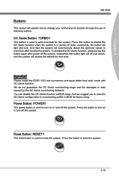
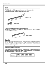
... G# INT H# 2-20 The PCI IRQ pins are hardware lines over which devices can send interrupt signals to the PCI bus pins as jumpers, switches or BIOS configuration. Hardware Setup Slots PCIE (Peripheral Component Interconnect Express) Slot The PCIE slot supports the PCIE interface expansion card. PCI Interrupt Request Routing The IRQ...
... G# INT H# 2-20 The PCI IRQ pins are hardware lines over which devices can send interrupt signals to the PCI bus pins as jumpers, switches or BIOS configuration. Hardware Setup Slots PCIE (Peripheral Component Interconnect Express) Slot The PCIE slot supports the PCIE interface expansion card. PCI Interrupt Request Routing The IRQ...

User Guide
Page 39
...and GPNV area. Initializes NUM-LOCK status and programs the KBD typematic rate. Initializes IPL devices controlled by BIOS and option ROMs. Late POST initialization of chipset registers. Early POST initialization of chipset registers. Initializes different devices through DIM. ...Also initialize BIOS modules on CPUID value in KBC port. Initializes different devices. Detects the presence of chipset registers. Check if waking ...
...and GPNV area. Initializes NUM-LOCK status and programs the KBD typematic rate. Initializes IPL devices controlled by BIOS and option ROMs. Late POST initialization of chipset registers. Early POST initialization of chipset registers. Initializes different devices through DIM. ...Also initialize BIOS modules on CPUID value in KBC port. Initializes different devices. Detects the presence of chipset registers. Check if waking ...

User Guide
Page 41
Chapter 3 BIOS Setup This chapter provides information on the screen during the system booting up, and requests you to change the default settings for optimum use. You may need to run the Setup program when: ■ An error message appears on the BIOS Setup program and allows you to run SETUP. ■ You want to configure the system for customized features.
Chapter 3 BIOS Setup This chapter provides information on the screen during the system booting up, and requests you to change the default settings for optimum use. You may need to run the Setup program when: ■ An error message appears on the BIOS Setup program and allows you to run SETUP. ■ You want to configure the system for customized features.

User Guide
Page 42
... Power on the screen, press key to the customer as I = Intel, N = nVidia, A = AMD and V = VIA. 7th - 8th digit refers to enter Setup. It is the BIOS version. Press DEL to enter Setup Menu, F11 to enter Boot Menu If the message disappears before you respond and you still wish to the.... • Upon boot-up, the 1st line appearing after the memory count is usually in the format: E7640AMS.xxx 041211 where: 1st digit refers to BIOS type as E = EFI 2nd - 5th digit refers to the model number. 6th digit refers to the chipset as MS = all standard customers. xxx refers to...
... Power on the screen, press key to the customer as I = Intel, N = nVidia, A = AMD and V = VIA. 7th - 8th digit refers to enter Setup. It is the BIOS version. Press DEL to enter Setup Menu, F11 to enter Boot Menu If the message disappears before you respond and you still wish to the.... • Upon boot-up, the 1st line appearing after the memory count is usually in the format: E7640AMS.xxx 041211 where: 1st digit refers to BIOS type as E = EFI 2nd - 5th digit refers to the model number. 6th digit refers to the chipset as MS = all standard customers. xxx refers to...
User Guide
Page 43
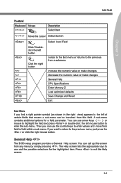
...-click the left of certain fields that means a sub-menu can be launched from this screen from any menu by simply pressing . General Help The BIOS setup program provides a General Help screen. A sub-menu contains additional options for the highlighted item. Chapter 3 MS-7640 Control Keyboard Mouse Description Select Item Move...
...-click the left of certain fields that means a sub-menu can be launched from this screen from any menu by simply pressing . General Help The BIOS setup program provides a General Help screen. A sub-menu contains additional options for the highlighted item. Chapter 3 MS-7640 Control Keyboard Mouse Description Select Item Move...
User Guide
Page 44
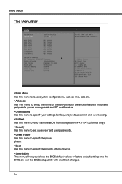
... configurations, such as time, date etc. ▶ Advanced Use this menu to load the BIOS default values or factory default settings into the BIOS and exit the BIOS setup utility with or without changes. 3-4 BIOS Setup The Menu Bar ▶ Main Menu Use this menu for frequency/voltage control and overclocking.... ▶ M-Flash Use this menu to read/ flash the BIOS from storage drive (FAT/ FAT32 format only). ▶ Security Use this menu to set supervisor and user passwords. ▶ Green Power Use this...
... configurations, such as time, date etc. ▶ Advanced Use this menu to load the BIOS default values or factory default settings into the BIOS and exit the BIOS setup utility with or without changes. 3-4 BIOS Setup The Menu Bar ▶ Main Menu Use this menu for frequency/voltage control and overclocking.... ▶ M-Flash Use this menu to read/ flash the BIOS from storage drive (FAT/ FAT32 format only). ▶ Security Use this menu to set supervisor and user passwords. ▶ Green Power Use this...

User Guide
Page 45
...sub-menu. through Dec. [date] The date from 1 to 31 can be keyed by numeric function keys. [year] The year can be adjusted by BIOS. Readonly. [month] The month from Sun to Sat, determined by users. ▶ System Time This allows you to set the system to the date ... Port1~2 are appearing when you connect the HD devices to the SATA connectors on the mainboard. ▶ System Information This area shows the CPU information, BIOS version and memory status of installed SATA device. The time format is . [day] Day of the week, from Jan. Main Menu MS-7640 Chapter 3...
...sub-menu. through Dec. [date] The date from 1 to 31 can be keyed by numeric function keys. [year] The year can be adjusted by BIOS. Readonly. [month] The month from Sun to Sat, determined by users. ▶ System Time This allows you to set the system to the date ... Port1~2 are appearing when you connect the HD devices to the SATA connectors on the mainboard. ▶ System Information This area shows the CPU information, BIOS version and memory status of installed SATA device. The time format is . [day] Day of the week, from Jan. Main Menu MS-7640 Chapter 3...

User Guide
Page 46
... enter the sub-menu. ▶ ACPI Standby State This item specifies the power saving modes for a longer time and thus improve the effective PCI bandwidth. BIOS Setup Advanced ▶ PCI Subsystem Settings Press to enter the sub-menu. ▶ PCI Latency Timer This item controls how long each PCI device can...
... enter the sub-menu. ▶ ACPI Standby State This item specifies the power saving modes for a longer time and thus improve the effective PCI bandwidth. BIOS Setup Advanced ▶ PCI Subsystem Settings Press to enter the sub-menu. ▶ PCI Latency Timer This item controls how long each PCI device can...
User Guide
Page 48
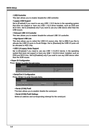
BIOS Setup ▶ USB Controller This item allows you to enable/ disable the USB controller. ▶ Legacy USB Support Set to [Enabled] if you need to ...
BIOS Setup ▶ USB Controller This item allows you to enable/ disable the USB controller. ▶ Legacy USB Support Set to [Enabled] if you need to ...

User Guide
Page 50
...; Wake Up Event Setup Press to enter the sub-menu. ▶ Wake Up Event By Setting to [BIOS] activates the following fields, and use the following fields to set to [Enabled], the feature allows your system to be awakened from the power saving ...
...; Wake Up Event Setup Press to enter the sub-menu. ▶ Wake Up Event By Setting to [BIOS] activates the following fields, and use the following fields to set to [Enabled], the feature allows your system to be awakened from the power saving ...

User Guide
Page 52
.../ HT Link Voltage/ DDR Vref Voltage/ CPU DDR-PHY Voltage/ NB PCI-E Voltage/ DDR VTT Voltage These items are used to enter the sub-menu. BIOS Setup • The greater the Spread Spectrum value is, the greater the EMI is available only when the processor supports this item as [1, 3] will become...
.../ HT Link Voltage/ DDR Vref Voltage/ CPU DDR-PHY Voltage/ NB PCI-E Voltage/ DDR VTT Voltage These items are used to enter the sub-menu. BIOS Setup • The greater the Spread Spectrum value is, the greater the EMI is available only when the processor supports this item as [1, 3] will become...

User Guide
Page 54
Setting to set the Hyper-Transport Link width. BIOS Setup ▶ HT Link Control Press to enter the sub-menu. ▶ HT Incoming/ Outgoing Link Width These items allow you to [Auto], the system will detect the HT link width automatically. 3-14
Setting to set the Hyper-Transport Link width. BIOS Setup ▶ HT Link Control Press to enter the sub-menu. ▶ HT Incoming/ Outgoing Link Width These items allow you to [Auto], the system will detect the HT link width automatically. 3-14
User Guide
Page 55
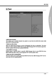
...Note: it only supports FAT/ 32 file system drive. ▶ Select one file to Boot When the BIOS Boot function as sets to [Enabled], this item is selectable. This item allows to select particular BIOS file from the BIOS file inside USB drive (FAT/ 32 format only). ▶ Select one file to update... BIOS This item allows you to enable/ disable the system to boot from the USB/ Storage (FAT/ 32 ...
...Note: it only supports FAT/ 32 file system drive. ▶ Select one file to Boot When the BIOS Boot function as sets to [Enabled], this item is selectable. This item allows to select particular BIOS file from the BIOS file inside USB drive (FAT/ 32 format only). ▶ Select one file to update... BIOS This item allows you to enable/ disable the system to boot from the USB/ Storage (FAT/ 32 ...
User Guide
Page 56
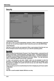
... person from CMOS memory. Important When you select the Administrator Password / User Password item, a password box will boot and you try to enter BIOS Setup. ▶ User Password This item is used to set password from changing any part of your system configuration. ▶ U-Key This item... to set the administrator password. To clear a set password, just press when you try to enable/ disable USB drive as a key. 3-16 BIOS Setup Security ▶ Administrator Password This item is used to enter the operating system. When a administrator password has been set, you will be prompted...
... person from CMOS memory. Important When you select the Administrator Password / User Password item, a password box will boot and you try to enter BIOS Setup. ▶ User Password This item is used to set password from changing any part of your system configuration. ▶ U-Key This item... to set the administrator password. To clear a set password, just press when you try to enable/ disable USB drive as a key. 3-16 BIOS Setup Security ▶ Administrator Password This item is used to enter the operating system. When a administrator password has been set, you will be prompted...
User Guide
Page 58
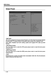
To reduce Power Consumption when system off or standby mode. BIOS Setup Green Power ▶ EUP 2013 This item is designed for Energy Using Products Lot 6 2013 (EuP) aka Energy Related Products (ErP). Note: When "Enabled" ...
To reduce Power Consumption when system off or standby mode. BIOS Setup Green Power ▶ EUP 2013 This item is designed for Energy Using Products Lot 6 2013 (EuP) aka Energy Related Products (ErP). Note: When "Enabled" ...
User Guide
Page 60
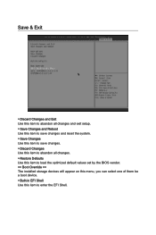
Save & Exit ▶ Discard Changes and Exit Use this item to abandon all changes and exit setup. ▶ Save Changes and Reboot Use this item to save changes and reset the system. ▶ Save Changes Use this item to save changes. ▶ Discard Changes Use this item to abandon all changes. ▶ Restore Defaults Use this item to load the optimized default values set by the BIOS vendor. == Boot Override == The installed storage devices will appear on this menu, you can select one of them be a boot device. ▶ Built-in EFI Shell Use this item to enter the EFI Shell.
Save & Exit ▶ Discard Changes and Exit Use this item to abandon all changes and exit setup. ▶ Save Changes and Reboot Use this item to save changes and reset the system. ▶ Save Changes Use this item to save changes. ▶ Discard Changes Use this item to abandon all changes. ▶ Restore Defaults Use this item to load the optimized default values set by the BIOS vendor. == Boot Override == The installed storage devices will appear on this menu, you can select one of them be a boot device. ▶ Built-in EFI Shell Use this item to enter the EFI Shell.


