User Guide
Page 2
... trademark of Realtek Semiconductor Corporation. ■ JMicron® is registered trademark of JMicron Technology Corporation. ■ Netware® is given as to make changes without notice. Revision History Revision V2.0 Revision History First release for FAQ, technical guide, BIOS updates, driver updates, and other information: http://www.msi.com/service/download/ ◙ Contact our technical staff at: http://support.msi.com/ ii
... trademark of Realtek Semiconductor Corporation. ■ JMicron® is registered trademark of JMicron Technology Corporation. ■ Netware® is given as to make changes without notice. Revision History Revision V2.0 Revision History First release for FAQ, technical guide, BIOS updates, driver updates, and other information: http://www.msi.com/service/download/ ◙ Contact our technical staff at: http://support.msi.com/ ii
User Guide
Page 8
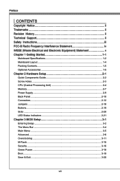
... Support ii Safety Instructions iii FCC-B Radio Frequency Interference Statement iv WEEE (Waste Electrical and Electronic Equipment) Statement v Chapter 1 Getting Started 1-1 Mainboard Specifications 1-2 Mainboard Layout 1-4 Packing Contents 1-5 Optional Accessories 1-5 Chapter 2 Hardware Setup 2-1 Quick Components Guide 2-2 Screw Holes 2-3 CPU (Central Processing Unit 2-4 Memory 2-7 Power Supply 2-9 Back Panel 2-10 Connectors 2-12 Jumpers 2-18 Buttons 2-19 Slots 2-20 LED Status Indicators 2-21 Chapter 3 BIOS Setup 3-1 Entering Setup 3-2 The Menu Bar 3-4 Main Menu...
... Support ii Safety Instructions iii FCC-B Radio Frequency Interference Statement iv WEEE (Waste Electrical and Electronic Equipment) Statement v Chapter 1 Getting Started 1-1 Mainboard Specifications 1-2 Mainboard Layout 1-4 Packing Contents 1-5 Optional Accessories 1-5 Chapter 2 Hardware Setup 2-1 Quick Components Guide 2-2 Screw Holes 2-3 CPU (Central Processing Unit 2-4 Memory 2-7 Power Supply 2-9 Back Panel 2-10 Connectors 2-12 Jumpers 2-18 Buttons 2-19 Slots 2-20 LED Status Indicators 2-21 Chapter 3 BIOS Setup 3-1 Entering Setup 3-2 The Menu Bar 3-4 Main Menu...
User Guide
Page 12
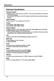
... ■ Chip integrated by VIA® VT6315N ■ 2 IEEE 1394 ports Audio ■ HD audio codec integrated by Realtek® ALC892 ■ Flexible 8-channel audio with jack sensing SATA ■ 6 SATA 6Gb/s ports (SATA1~6) by AMD® SB950 ■ 2 eSATA/ USB Combo ports by JMicron® JMB362 ■ Supports hot plug & asynchronous notification USB 3.0 ■ 2 USB 3.0 ports (back panel) and 1 USB 3.0 connector by NEC D720200 RAID ■ SATA1~6 support RAID 0/ 1/ 5/ 10 mode by AMD®...
... ■ Chip integrated by VIA® VT6315N ■ 2 IEEE 1394 ports Audio ■ HD audio codec integrated by Realtek® ALC892 ■ Flexible 8-channel audio with jack sensing SATA ■ 6 SATA 6Gb/s ports (SATA1~6) by AMD® SB950 ■ 2 eSATA/ USB Combo ports by JMicron® JMB362 ■ Supports hot plug & asynchronous notification USB 3.0 ■ 2 USB 3.0 ports (back panel) and 1 USB 3.0 connector by NEC D720200 RAID ■ SATA1~6 support RAID 0/ 1/ 5/ 10 mode by AMD®...
User Guide
Page 13
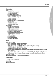
.../2 keyboard port - 1 PS/2 mouse port - 1 Clear CMOS button - 1 Coaxial S/PDIF-Out port - 1 Optical S/PDIF-Out port - 4 USB 2.0 ports - 2 USB 3.0 ports - 2 eSATA/ USB 2.0 Combo ports - 1 LAN port - 1 IEEE 1394 port - 6 flexible audio ports ■ On-Board - 2 USB 2.0 connectors - 1 IEEE 1394 connector - 1 Serial port connector - 1 Chassis Intrusion connector - 1 S/PDIF-Out connector - 1 Front Panel Audio connector - 1 TPM Module connector - 1 Power button - 1 Reset button - 1 OC Genie button - 1 Debug LED panel Slots ■ 4 PCIE x16 slots - PCI_E4 supports up to PCIE x8 speed - PCI_E5...
.../2 keyboard port - 1 PS/2 mouse port - 1 Clear CMOS button - 1 Coaxial S/PDIF-Out port - 1 Optical S/PDIF-Out port - 4 USB 2.0 ports - 2 USB 3.0 ports - 2 eSATA/ USB 2.0 Combo ports - 1 LAN port - 1 IEEE 1394 port - 6 flexible audio ports ■ On-Board - 2 USB 2.0 connectors - 1 IEEE 1394 connector - 1 Serial port connector - 1 Chassis Intrusion connector - 1 S/PDIF-Out connector - 1 Front Panel Audio connector - 1 TPM Module connector - 1 Power button - 1 Reset button - 1 OC Genie button - 1 Debug LED panel Slots ■ 4 PCIE x16 slots - PCI_E4 supports up to PCIE x8 speed - PCI_E5...
User Guide
Page 26
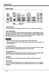
... speakers through an optical fiber cable. ▶ 1394 Port The IEEE1394 port on the back panel provides connection to clear data. With the CMOS RAM, the system can automatically boot OS every time it is turned on board that you want to clear the system configuration, use the button to IEEE1394 devices. ▶ USB 2.0 Port The USB (Universal Serial Bus) port is for a PS/2® mouse/keyboard. ▶ Clear CMOS Button There is a CMOS RAM on . Hardware Setup Back Panel Coaxial LAN...
... speakers through an optical fiber cable. ▶ 1394 Port The IEEE1394 port on the back panel provides connection to clear data. With the CMOS RAM, the system can automatically boot OS every time it is turned on board that you want to clear the system configuration, use the button to IEEE1394 devices. ▶ USB 2.0 Port The USB (Universal Serial Bus) port is for a PS/2® mouse/keyboard. ▶ Clear CMOS Button There is a CMOS RAM on . Hardware Setup Back Panel Coaxial LAN...
User Guide
Page 29
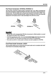
Chapter 2 MS-7640 Fan Power Connectors: CPUFAN, SYSFAN1~4 The fan power connectors support system cooling fan with speed sensor to take advantage of the CPU fan control. If the mainboard has a System Hardware Monitor chipset on-board, you to connect the front panel audio and is Ground and should be connected to the +12V; You can install Control Center utility that the red wire is the positive and should be connected to GND. CPUFAN 4.3C.oS2n...
Chapter 2 MS-7640 Fan Power Connectors: CPUFAN, SYSFAN1~4 The fan power connectors support system cooling fan with speed sensor to take advantage of the CPU fan control. If the mainboard has a System Hardware Monitor chipset on-board, you to connect the front panel audio and is Ground and should be connected to the +12V; You can install Control Center utility that the red wire is the positive and should be connected to GND. CPUFAN 4.3C.oS2n...
User Guide
Page 31
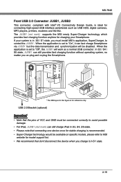
... you un-plug and re-plug the Smartphone. * The MB layout in S1 state. 2-15 USB 2.0 Bracket (optional) Important • Note that the pins of VCC and GND must install MSI's application, SuperCharger, to MSI website for reference only. The JUSB1 (red mark) supports the MSI newly Super-Charger technology which provides fast charging function anytime for charging your system is set to...
... you un-plug and re-plug the Smartphone. * The MB layout in S1 state. 2-15 USB 2.0 Bracket (optional) Important • Note that the pins of VCC and GND must install MSI's application, SuperCharger, to MSI website for reference only. The JUSB1 (red mark) supports the MSI newly Super-Charger technology which provides fast charging function anytime for charging your system is set to...
User Guide
Page 34
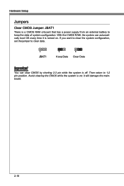
Avoid clearing the CMOS while the system is off. If you want to clear the system configuration, set the jumper to 1-2 pin position. it is a CMOS RAM onboard that has a power supply from an external battery to keep the data of system configuration. Then return to clear data. 1 JBAT1 1 Keep Data 1 Clear Data Important You can automatically boot OS every time it will damage the mainboard. 2-18 Hardware Setup Jumpers Clear CMOS Jumper: JBAT1 There is turned on ; With the CMOS RAM, the system can clear CMOS by shorting 2-3 pin while the system is on .
Avoid clearing the CMOS while the system is off. If you want to clear the system configuration, set the jumper to 1-2 pin position. it is a CMOS RAM onboard that has a power supply from an external battery to keep the data of system configuration. Then return to clear data. 1 JBAT1 1 Keep Data 1 Clear Data Important You can automatically boot OS every time it will damage the mainboard. 2-18 Hardware Setup Jumpers Clear CMOS Jumper: JBAT1 There is turned on ; With the CMOS RAM, the system can clear CMOS by shorting 2-3 pin while the system is on .
User Guide
Page 35
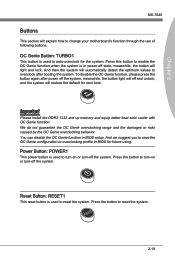
... boot. Reset Button: RESET1 This reset button is in BIOS setup. Press this button to enable the OC Genie function when the system is used to auto-overclock for future using. To disable the OC Genie function, please press the button again after booting the system. OC Genie Button: TURBO1 This button is used to reset the system. Chapter 2 MS-7640 Buttons This section will light and lock. Power Button: POWER1 This power button is used to turn...
... boot. Reset Button: RESET1 This reset button is in BIOS setup. Press this button to enable the OC Genie function when the system is used to auto-overclock for future using. To disable the OC Genie function, please press the button again after booting the system. OC Genie Button: TURBO1 This button is used to reset the system. Chapter 2 MS-7640 Buttons This section will light and lock. Power Button: POWER1 This power button is used to turn...
User Guide
Page 36
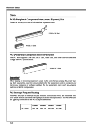
...the PCI bus pins as jumpers, switches or BIOS configuration. PCI Interrupt Request Routing The IRQ, acronym of interrupt request line and pronounced I-R-Q, are typically connected to the microprocessor. Hardware Setup Slots PCIE (Peripheral Component Interconnect Express) Slot The PCIE slot supports the PCIE interface expansion card. PCIE x16 Slot PCIE x1 Slot PCI (Peripheral Component Interconnect) Slot The PCI slot supports LAN card, SCSI card, USB card, and other add-on cards that comply with PCI specifications. 32-bit PCI Slot Important When adding or removing expansion cards, make...
...the PCI bus pins as jumpers, switches or BIOS configuration. PCI Interrupt Request Routing The IRQ, acronym of interrupt request line and pronounced I-R-Q, are typically connected to the microprocessor. Hardware Setup Slots PCIE (Peripheral Component Interconnect Express) Slot The PCIE slot supports the PCIE interface expansion card. PCIE x16 Slot PCIE x1 Slot PCI (Peripheral Component Interconnect) Slot The PCI slot supports LAN card, SCSI card, USB card, and other add-on cards that comply with PCI specifications. 32-bit PCI Slot Important When adding or removing expansion cards, make...

User Guide
Page 46
.... ▶ ACPI Settings Press to enter the sub-menu. ▶ ACPI Standby State This item specifies the power saving modes for a longer time and thus improve the effective PCI bandwidth. BIOS Setup Advanced ▶ PCI Subsystem Settings Press to enter the sub-menu. ▶ PCI Latency Timer This item controls how long each PCI device can conduct transactions for ACPI function. ▶ Power LED This item configures how the system uses power LED on the case to...
.... ▶ ACPI Settings Press to enter the sub-menu. ▶ ACPI Standby State This item specifies the power saving modes for a longer time and thus improve the effective PCI bandwidth. BIOS Setup Advanced ▶ PCI Subsystem Settings Press to enter the sub-menu. ▶ PCI Latency Timer This item controls how long each PCI device can conduct transactions for ACPI function. ▶ Power LED This item configures how the system uses power LED on the case to...

User Guide
Page 47
... used to specify a mode for E-SATA port. ▶ HD Audio Controller This item allows you to enable/ disable the onboard IEEE 1394 controller. ▶ SATA Mode This item is used to specify a mode for SATA port. ▶ Onboard E-SATA Controller Mode This item is part of installed USB device. 3-7 MS-7640 Chapter 3 ▶ Onboard Lan Controller This item allows you to enable/ disable the onboard LAN controller. ▶ LAN Option ROM This item is used to decide whether to invoke the Boot ROM of the onboard LAN. ▶ Onboard IEEE 1394 Controller...
... used to specify a mode for E-SATA port. ▶ HD Audio Controller This item allows you to enable/ disable the onboard IEEE 1394 controller. ▶ SATA Mode This item is used to specify a mode for SATA port. ▶ Onboard E-SATA Controller Mode This item is part of installed USB device. 3-7 MS-7640 Chapter 3 ▶ Onboard Lan Controller This item allows you to enable/ disable the onboard LAN controller. ▶ LAN Option ROM This item is used to decide whether to invoke the Boot ROM of the onboard LAN. ▶ Onboard IEEE 1394 Controller...
User Guide
Page 48
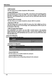
... USB mouse. ▶ Onboard USB 3.0 Controller This item allows you to enable/ disable the onboard USB 3.0 controller. ▶ High-Speed USB Link This item allows you need to use any USB 1.1/2.0 device in the operating system that does not support or have any USB 1.1/2.0 driver installed, such as DOS and SCO Unix. Set to [Standard] the USB 2.0 ports will be allocated to NEC chip. ▶ USB 3.0 Legacy Mode Support Set to [Enabled] if you to enable/ disable the serial port. ▶ Serial (COM) Port0 Settings...
... USB mouse. ▶ Onboard USB 3.0 Controller This item allows you to enable/ disable the onboard USB 3.0 controller. ▶ High-Speed USB Link This item allows you need to use any USB 1.1/2.0 device in the operating system that does not support or have any USB 1.1/2.0 driver installed, such as DOS and SCO Unix. Set to [Standard] the USB 2.0 ports will be allocated to NEC chip. ▶ USB 3.0 Legacy Mode Support Set to [Enabled] if you to enable/ disable the serial port. ▶ Serial (COM) Port0 Settings...

User Guide
Page 50
BIOS Setup ▶ Wake Up Event Setup Press to enter the sub-menu. ▶ Wake Up Event By Setting to [BIOS] activates the following fields, and use the following fields to set to [Enabled], the feature allows your system to be awakened from the power saving modes through any event on a specific date/hour/minute/second specified in these fields (using the and to RAM) sleep state. ▶ Resume...
BIOS Setup ▶ Wake Up Event Setup Press to enter the sub-menu. ▶ Wake Up Event By Setting to [BIOS] activates the following fields, and use the following fields to set to [Enabled], the feature allows your system to be awakened from the power saving modes through any event on a specific date/hour/minute/second specified in these fields (using the and to RAM) sleep state. ▶ Resume...
User Guide
Page 55
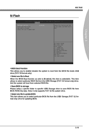
...) drive for updating BIOS. 3-15 M-Flash MS-7640 Chapter 3 ▶ BIOS Boot Function This allows you to select particular BIOS file from the BIOS file inside USB drive (FAT/ 32 format only). ▶ Select one file to Boot When the BIOS Boot function as sets to [Enabled], this item is selectable. And the system will boot from selected BIOS file. ▶ Save BIOS to storage Please setup a specific folder in specific USB/ Storage drive to select particular BIOS file from BIOS ROM chip data...
...) drive for updating BIOS. 3-15 M-Flash MS-7640 Chapter 3 ▶ BIOS Boot Function This allows you to select particular BIOS file from the BIOS file inside USB drive (FAT/ 32 format only). ▶ Select one file to Boot When the BIOS Boot function as sets to [Enabled], this item is selectable. And the system will boot from selected BIOS file. ▶ Save BIOS to storage Please setup a specific folder in specific USB/ Storage drive to select particular BIOS file from BIOS ROM chip data...
User Guide
Page 57
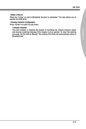
The setting of recording the chassis intrusion status and issuing a warning message if the chassis is selectable. This item allows you to specify the USB drive. ▶ Chassis Intrusion Configuration Press to enter the sub-menu. ▶ Chassis Intrusion This item enables or disables the feature of the field will automatically return to [Enabled] later. 3-17 To clear the warning message, set the field to [Reset]. Chapter 3 MS-7640 ▶ Make U-Key at When the "U-Key" as sets to [Enabled], this item is once opened.
The setting of recording the chassis intrusion status and issuing a warning message if the chassis is selectable. This item allows you to specify the USB drive. ▶ Chassis Intrusion Configuration Press to enter the sub-menu. ▶ Chassis Intrusion This item enables or disables the feature of the field will automatically return to [Enabled] later. 3-17 To clear the warning message, set the field to [Reset]. Chapter 3 MS-7640 ▶ Make U-Key at When the "U-Key" as sets to [Enabled], this item is once opened.
User Guide
Page 60
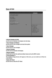
Save & Exit ▶ Discard Changes and Exit Use this item to abandon all changes and exit setup. ▶ Save Changes and Reboot Use this item to save changes and reset the system. ▶ Save Changes Use this item to save changes. ▶ Discard Changes Use this item to abandon all changes. ▶ Restore Defaults Use this item to load the optimized default values set by the BIOS vendor. == Boot Override == The installed storage devices will appear on this menu, you can select one of them be a boot device. ▶ Built-in EFI Shell Use this item to enter the EFI Shell.
Save & Exit ▶ Discard Changes and Exit Use this item to abandon all changes and exit setup. ▶ Save Changes and Reboot Use this item to save changes and reset the system. ▶ Save Changes Use this item to save changes. ▶ Discard Changes Use this item to abandon all changes. ▶ Restore Defaults Use this item to load the optimized default values set by the BIOS vendor. == Boot Override == The installed storage devices will appear on this menu, you can select one of them be a boot device. ▶ Built-in EFI Shell Use this item to enter the EFI Shell.

User Guide
Page 62
... the DVD-ROM drive. Click here 4. Follow the on Windows® 7 environment and could look slightly different if you can get access to 2-, 4-, 6-, 8- cally appear. 2. Click Next to start installing the drivers. 5. Hence, the program screens shown here in this section may be slightly different from the latest software utility and shall be held for Windows® For Windows® XP, you must install Windows...
... the DVD-ROM drive. Click here 4. Follow the on Windows® 7 environment and could look slightly different if you can get access to 2-, 4-, 6-, 8- cally appear. 2. Click Next to start installing the drivers. 5. Hence, the program screens shown here in this section may be slightly different from the latest software utility and shall be held for Windows® For Windows® XP, you must install Windows...
User Guide
Page 74
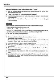
... copy the files to a medium (floppy/ CD/ DVD or USB) Important Please follow the instruction below to make a SATA RAID driver for yourself. • Insert the MSI DVD into the DVD-ROM drive. • Click the "Browse CD" on "Load Driver" button to OS.) • The driver disk for the Windows Setup screen to continue. 8. The next screen should be shown a list of available RAID controller(s). 6. B-8 For Windows Vista/ Windows 7: During the Operating system installation, after the RAID volume...
... copy the files to a medium (floppy/ CD/ DVD or USB) Important Please follow the instruction below to make a SATA RAID driver for yourself. • Insert the MSI DVD into the DVD-ROM drive. • Click the "Browse CD" on "Load Driver" button to OS.) • The driver disk for the Windows Setup screen to continue. 8. The next screen should be shown a list of available RAID controller(s). 6. B-8 For Windows Vista/ Windows 7: During the Operating system installation, after the RAID volume...
User Guide
Page 75
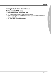
Under the Driver tab, click on AMD chipset drivers by your need. Appendix B MS-7640 Installing the RAID Driver Under Windows (for Non-bootable RAID Array) 1. The AMD chipset drivers includes RAID Driver. 4. The driver will appear. 3. The DVD will auto-run and the setup screen will be automatically installed. B-9 Insert the MSI DVD into the DVD-ROM drive. 2.
Under the Driver tab, click on AMD chipset drivers by your need. Appendix B MS-7640 Installing the RAID Driver Under Windows (for Non-bootable RAID Array) 1. The AMD chipset drivers includes RAID Driver. 4. The driver will appear. 3. The DVD will auto-run and the setup screen will be automatically installed. B-9 Insert the MSI DVD into the DVD-ROM drive. 2.


