
User Guide
Page 2
... States and/or other information: http://www.msi.com.tw/program/service/faq/ faq/esc_faq_list.php Contact our technical staff at: support@msi.com.tw ii Alternatively, please try the following help resources for FAQ, technical guide, BIOS updates, driver updates, and other countries. ...First release for PCB 3.X Date August 2006 Technical Support If a problem arises with your place of purchase or local distributor. Visit the MSI website for further guidance. Intel® and Pentium® are registered trademarks of Intel Corporation. Netware® is a registered trademark of...
... States and/or other information: http://www.msi.com.tw/program/service/faq/ faq/esc_faq_list.php Contact our technical staff at: support@msi.com.tw ii Alternatively, please try the following help resources for FAQ, technical guide, BIOS updates, driver updates, and other countries. ...First release for PCB 3.X Date August 2006 Technical Support If a problem arises with your place of purchase or local distributor. Visit the MSI website for further guidance. Intel® and Pentium® are registered trademarks of Intel Corporation. Netware® is a registered trademark of...
User Guide
Page 9
Jumpers ...2-19 Clear CMOS Jumper: JBAT1 2-19 Slots ...2-20 PCI (Peripheral Component Interconnect) Express Slots 2-20 PCI (Peripheral Component Interconnect) Slots 2-20 PCI Interrupt Request Routing 2-21 Chapter 3 BIOS Setup 3-1 Entering Setup ...3-2 Control Keys 3-3 Getting Help 3-3 General Help
Jumpers ...2-19 Clear CMOS Jumper: JBAT1 2-19 Slots ...2-20 PCI (Peripheral Component Interconnect) Express Slots 2-20 PCI (Peripheral Component Interconnect) Slots 2-20 PCI Interrupt Request Routing 2-21 Chapter 3 BIOS Setup 3-1 Entering Setup ...3-2 Control Keys 3-3 Getting Help 3-3 General Help
User Guide
Page 13
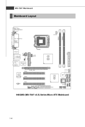
MS-7267 Mainboard Mainboard Layout Top : mouse Bottom: keyboard Top : Parallel Port Bottom: COM A VGA Port CP UFA N1 DIMM1 DIMM2 USB ports JCI1 T: LAN jack B: USB ports JPW1 JIR1 T:L i ne -I /O ATX1 JCOM2 ( op t io n al ) LAN Chip (optional) PCI3 PCIE_X16 PCI2 ALC883 PCI1 JAUD1 CD_IN1 JSPD1 ( Op tio na l) Intel 945G FDD1 SYS FA N1 PWRFAN1 BATT + BIOS JB AT1 JFP2 JFP1 JUSB2 JUSB1 IDE 1 945GM3 (MS-7267 v3.X) Series Micro-ATX Mainboard S ATA 4 SATA1 SATA2 SATA3 1-4 Ou t M:CS-Out B:S S-Out Winbond I n M:Li ne-Out B:Mic T:R S-
MS-7267 Mainboard Mainboard Layout Top : mouse Bottom: keyboard Top : Parallel Port Bottom: COM A VGA Port CP UFA N1 DIMM1 DIMM2 USB ports JCI1 T: LAN jack B: USB ports JPW1 JIR1 T:L i ne -I /O ATX1 JCOM2 ( op t io n al ) LAN Chip (optional) PCI3 PCIE_X16 PCI2 ALC883 PCI1 JAUD1 CD_IN1 JSPD1 ( Op tio na l) Intel 945G FDD1 SYS FA N1 PWRFAN1 BATT + BIOS JB AT1 JFP2 JFP1 JUSB2 JUSB1 IDE 1 945GM3 (MS-7267 v3.X) Series Micro-ATX Mainboard S ATA 4 SATA1 SATA2 SATA3 1-4 Ou t M:CS-Out B:S S-Out Winbond I n M:Li ne-Out B:Mic T:R S-
User Guide
Page 22
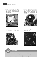
Press down the load lever lightly onto the load plate, and then secure the lever with the plastic cap covered (shown in BIOS (Chapter 3) for the CPU temperature. 2. Align the holes on it) to lock the h ook s . 12. Push down to confirm that the clip-ends are correctly ...
Press down the load lever lightly onto the load plate, and then secure the lever with the plastic cap covered (shown in BIOS (Chapter 3) for the CPU temperature. 2. Align the holes on it) to lock the h ook s . 12. Push down to confirm that the clip-ends are correctly ...
User Guide
Page 30
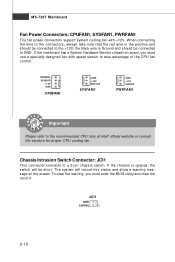
..., always take advantage of the CPU fan c on tr ol . The system will be connected to GND. To clear the warning, you must enter the BIOS utility and clear the record. If the mainboard has a System Hardware Monitor chipset on the screen. CONTROL SE NS OR +1 2V GND CPUFAN1 GND +12V...
..., always take advantage of the CPU fan c on tr ol . The system will be connected to GND. To clear the warning, you must enter the BIOS utility and clear the record. If the mainboard has a System Hardware Monitor chipset on the screen. CONTROL SE NS OR +1 2V GND CPUFAN1 GND +12V...
User Guide
Page 32
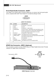
Right channel 4 PRESENCE# Active low signal - JAUD1 2 10 1 9 JAUD1 Pin Definition PIN SIGNAL DESCRIPTION 1 PORT 1L Analog Port 1 - signals BIOS that a High Definition Audio dongle is connected to JSPD1 JSPD1 VCC GND SPDIF 2-16 SPDIF Bracket (Optional) Left channel 2 GND Ground 3 PORT 1R Analog Port 1 - ...
Right channel 4 PRESENCE# Active low signal - JAUD1 2 10 1 9 JAUD1 Pin Definition PIN SIGNAL DESCRIPTION 1 PORT 1L Analog Port 1 - signals BIOS that a High Definition Audio dongle is connected to JSPD1 JSPD1 VCC GND SPDIF 2-16 SPDIF Bracket (Optional) Left channel 2 GND Ground 3 PORT 1R Analog Port 1 - ...
User Guide
Page 34
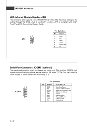
... Transmit Data Data Terminal Ready Ground Data Set Ready Request To Send Clear To Send Ring Indicate 2-18 You must configure the setting through the BIOS setup to use the IR function.
... Transmit Data Data Terminal Ready Ground Data Set Ready Request To Send Clear To Send Ring Indicate 2-18 You must configure the setting through the BIOS setup to use the IR function.
User Guide
Page 36
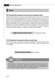
... graphics controllers, while PCI Express x1 supports transfer rate of 4.0 GB/s over a PCI Express x1 lane for the expansion card, such as jumpers, switches or BIOS configuration. 2-20 MS-7267 Mainboard Slots PCI (Peripheral Component Interconnect) Express Slots PCI Express architecture provides a high performance I /O. At 32 bits and 33 MHz, it...
... graphics controllers, while PCI Express x1 supports transfer rate of 4.0 GB/s over a PCI Express x1 lane for the expansion card, such as jumpers, switches or BIOS configuration. 2-20 MS-7267 Mainboard Slots PCI (Peripheral Component Interconnect) Express Slots PCI Express architecture provides a high performance I /O. At 32 bits and 33 MHz, it...
User Guide
Page 38
You may need to run the Setup program when: ² An error message appears on the BIOS Setup program and allows you to run SETUP. ² You want to configure the system for customized features. 3-1 Chapter 3 BIOS Setup BIOS Setup This chapter provides information on the screen during the system booting up, and requests you to change the default settings for optimum use.
You may need to run the Setup program when: ² An error message appears on the BIOS Setup program and allows you to run SETUP. ² You want to configure the system for customized features. 3-1 Chapter 3 BIOS Setup BIOS Setup This chapter provides information on the screen during the system booting up, and requests you to change the default settings for optimum use.
User Guide
Page 39
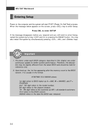
... appears on the computer and the system will start POST (Power On Self Test) process. You may be slightly different from the latest BIOS and should be held for better system performance. Important 1. Upon boot-up, the 1st line appearing after the memory count is usually in this... released. 3-2 Therefore, the description may also restart the system by turning it OFF and On or pressing the RESET button. It is the BIOS version. MS-7267 Mainboard Entering Setup Power on the screen, press key to enter Setup, restart the system by simultaneously pressing , , and keys. ...
... appears on the computer and the system will start POST (Power On Self Test) process. You may be slightly different from the latest BIOS and should be held for better system performance. Important 1. Upon boot-up, the 1st line appearing after the memory count is usually in this... released. 3-2 Therefore, the description may also restart the system by turning it OFF and On or pressing the RESET button. It is the BIOS version. MS-7267 Mainboard Entering Setup Power on the screen, press key to enter Setup, restart the system by simultaneously pressing , , and keys. ...
User Guide
Page 40
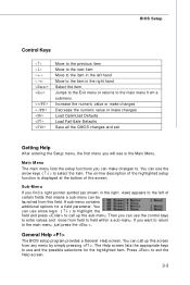
... lists the appropriate keys to use arrow keys ( ↑↓ ) to highlight the field and press to call up the sub-menu. General Help The BIOS setup program provides a General Help screen. The on-line description of the highlighted setup function is the Main Menu. You can use the control keys... you will see is displayed at the bottom of the screen. Sub-M enu If you want to return to the main menu, just press the . BIOS Setup Control Keys Enter> Move to the previous item Move to the next item Move to the item in the right hand Select the item...
... lists the appropriate keys to use arrow keys ( ↑↓ ) to highlight the field and press to call up the sub-menu. General Help The BIOS setup program provides a General Help screen. The on-line description of the highlighted setup function is the Main Menu. You can use the control keys... you will see is displayed at the bottom of the screen. Sub-M enu If you want to return to the main menu, just press the . BIOS Setup Control Keys Enter> Move to the previous item Move to the next item Move to the item in the right hand Select the item...
User Guide
Page 41
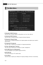
... and optimize your settings for basic system configurations, such as time, date etc. Advanced Chipset Setup Use this menu to specify your system's performance. Advanced BIOS Features Use this menu for frequency/voltage control and overclocking. 3-4 H/W Monitor This entry shows your system supports PnP/PCI. MS-7267 Mainboard The Main Menu...
... and optimize your settings for basic system configurations, such as time, date etc. Advanced Chipset Setup Use this menu to specify your system's performance. Advanced BIOS Features Use this menu for frequency/voltage control and overclocking. 3-4 H/W Monitor This entry shows your system supports PnP/PCI. MS-7267 Mainboard The Main Menu...
User Guide
Page 42
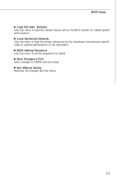
BIOS Setting Password Use this menu to CMOS and exit setup. Save Changes & Exit Save changes to set the password for BIOS. Load Optimized Defaults Use this menu to load the default values set by the BIOS vendor for stable system performance. Exit Without Saving Abandon all changes and exit setup. 3-5 BIOS Setup Load Fail Safe Defaults Use this menu to load the default values set by the mainboard manufacturer specifically for optimal performance of the mainboard.
BIOS Setting Password Use this menu to CMOS and exit setup. Save Changes & Exit Save changes to set the password for BIOS. Load Optimized Defaults Use this menu to load the default values set by the BIOS vendor for stable system performance. Exit Without Saving Abandon all changes and exit setup. 3-5 BIOS Setup Load Fail Safe Defaults Use this menu to load the default values set by the mainboard manufacturer specifically for optimal performance of the mainboard.
User Guide
Page 43
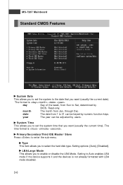
month The month from 1 to Sat, determined by users. through Dec. year The year can be adjusted by BIOS. Setting to Auto enables LBA mode if the device supports it and the devices is . MS-7267 Mainboard Standard CMOS Features System Date This allows ...
month The month from 1 to Sat, determined by users. through Dec. year The year can be adjusted by BIOS. Setting to Auto enables LBA mode if the device supports it and the devices is . MS-7267 Mainboard Standard CMOS Features System Date This allows ...
User Guide
Page 44
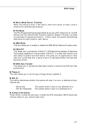
... move data from a hard disk that monitors your system (read or write more sector at boot. It shows the CPU information, BIOS version and memory status of floppy drives installed. BIOS Setup Block (Multi-Sector Transfer) W hen the setting is Auto, it will stop if an error is going to fail to...
... move data from a hard disk that monitors your system (read or write more sector at boot. It shows the CPU information, BIOS version and memory status of floppy drives installed. BIOS Setup Block (Multi-Sector Transfer) W hen the setting is Auto, it will stop if an error is going to fail to...
User Guide
Page 45
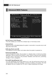
MS-7267 Mainboard Advanced BIOS Features Full Screen LOGO Display This item enables you to show the company logo on battery or AC power. W hen a malicious worm attempts to insert ...
MS-7267 Mainboard Advanced BIOS Features Full Screen LOGO Display This item enables you to show the company logo on battery or AC power. W hen a malicious worm attempts to insert ...
User Guide
Page 46
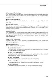
ACPI APIC support This item is to use, consult the vendor of boot devices where BIOS attempts to select the MPS version supported by your operating system is used for the operating system. To find out which MPS (Multi-Processor Specification) ... the system to try to boot from the 1st/2nd/3rd boot device. Removable Drives This feature allows you to enabled/ disabled the Vanderpool Technology. BIOS Setup Vanderpool Technology This setting allows you to specify the removable device boot priority. Max CPUID Value Limit: The Max CPUID Value Limit is designed...
ACPI APIC support This item is to use, consult the vendor of boot devices where BIOS attempts to select the MPS version supported by your operating system is used for the operating system. To find out which MPS (Multi-Processor Specification) ... the system to try to boot from the 1st/2nd/3rd boot device. Removable Drives This feature allows you to enabled/ disabled the Vanderpool Technology. BIOS Setup Vanderpool Technology This setting allows you to specify the removable device boot priority. Max CPUID Value Limit: The Max CPUID Value Limit is designed...
User Guide
Page 48
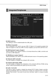
... DOS and SCO Unix. Onboard LAN Option ROM The item enables or disables the initialization of the onboard LAN Boot ROMs during bootup. Integrated Peripherals BIOS Setup USB Functions This setting is used to enable/disable the USB ports. Selecting [Enabled] allows the mainboard to enable the onboard AC'97 controller...
... DOS and SCO Unix. Onboard LAN Option ROM The item enables or disables the initialization of the onboard LAN Boot ROMs during bootup. Integrated Peripherals BIOS Setup USB Functions This setting is used to enable/disable the USB ports. Selecting [Enabled] allows the mainboard to enable the onboard AC'97 controller...

User Guide
Page 50
... port in ECP mode only. Parallel Port IRQ This item allows you to enable/ disable the floppy controller. Selecting [Auto] allows BIOS to automatically determine the correct base I /O port address. Parallel Port M ode [Normal] Standard Parallel Port [EPP] Enhanced Parallel Port ...Enhanced Parallel Port [Bi-Directional] To operate the onboard parallel port as Standard Parallel Port only, choose [SPP]. Selecting [Auto] allows BIOS to automatically determine the correct base I /O port address. By choosing [ECP], the onboard parallel port will allow the onboard parallel ...
... port in ECP mode only. Parallel Port IRQ This item allows you to enable/ disable the floppy controller. Selecting [Auto] allows BIOS to automatically determine the correct base I /O port address. Parallel Port M ode [Normal] Standard Parallel Port [EPP] Enhanced Parallel Port ...Enhanced Parallel Port [Bi-Directional] To operate the onboard parallel port as Standard Parallel Port only, choose [SPP]. Selecting [Auto] allows BIOS to automatically determine the correct base I /O port address. By choosing [ECP], the onboard parallel port will allow the onboard parallel ...
User Guide
Page 52
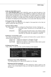
...-on state. [Last State] Restores the system to initialize the VGA card. Wakeup Event Setup Press to configure the Power Button function. BIOS Setup Re-Call VGA BIOS from S3 sleep state. If you choose [Specific Key], you press the power button, the computer enters the suspend/sleep mode, but ...more than four seconds, the computer is set to initialize the VGA card when system wakes up the system from S3. Selecting [Yes] allows BIOS to call VGABIOS to [S3/STR], users can select the options in this field. Power Button Mode This feature allows users to enter sub-menu...
...-on state. [Last State] Restores the system to initialize the VGA card. Wakeup Event Setup Press to configure the Power Button function. BIOS Setup Re-Call VGA BIOS from S3 sleep state. If you choose [Specific Key], you press the power button, the computer enters the suspend/sleep mode, but ...more than four seconds, the computer is set to initialize the VGA card when system wakes up the system from S3. Selecting [Yes] allows BIOS to call VGABIOS to [S3/STR], users can select the options in this field. Power Button Mode This feature allows users to enter sub-menu...


