
User Guide
Page 2
..., technical guide, BIOS updates, driver updates, and other countries. Copyright Notice The material in this document, but no solution can be obtained from the user's manual, please contact your system and no guarantee is given as to make changes without notice. We take every care in the preparation of this document is a registered trademark of M ICRO-STAR INTERNATIONAL. Award®...
..., technical guide, BIOS updates, driver updates, and other countries. Copyright Notice The material in this document, but no solution can be obtained from the user's manual, please contact your system and no guarantee is given as to make changes without notice. We take every care in the preparation of this document is a registered trademark of M ICRO-STAR INTERNATIONAL. Award®...
User Guide
Page 8
... Started 1-1 Mainboard Specifications 1-2 Mainboard Layout 1-4 Packing Checklist 1-4 MSI Special Feature 1-6 Core Center 1-6 Chapter 2 Getting Started 1-1 Quick Components Guide 2-2 CPU (Central Processing Unit 2-3 Introduction to LGA 775 CPU 2-3 CPU & Cooler Installation 2-4 Memory ...2-7 Installing DDRII Modules 2-8 Power Supply ...2-9 ATX 24-Pin Power Connector: ATX1 2-9 ATX 12V Power Connector: JPW 1 2-9 Back Panel ...2-10 Connectors ...2-12 Floppy Disk Drive Connector: FDD1 2-12 Hard Disk Connector: IDE1 2-12 Serial ATA Connectors: SATA1~SATA4 2-13 Fan Power Connectors...
... Started 1-1 Mainboard Specifications 1-2 Mainboard Layout 1-4 Packing Checklist 1-4 MSI Special Feature 1-6 Core Center 1-6 Chapter 2 Getting Started 1-1 Quick Components Guide 2-2 CPU (Central Processing Unit 2-3 Introduction to LGA 775 CPU 2-3 CPU & Cooler Installation 2-4 Memory ...2-7 Installing DDRII Modules 2-8 Power Supply ...2-9 ATX 24-Pin Power Connector: ATX1 2-9 ATX 12V Power Connector: JPW 1 2-9 Back Panel ...2-10 Connectors ...2-12 Floppy Disk Drive Connector: FDD1 2-12 Hard Disk Connector: IDE1 2-12 Serial ATA Connectors: SATA1~SATA4 2-13 Fan Power Connectors...
User Guide
Page 9
Jumpers ...2-19 Clear CMOS Jumper: JBAT1 2-19 Slots ...2-20 PCI (Peripheral Component Interconnect) Express Slots 2-20 PCI (Peripheral Component Interconnect) Slots 2-20 PCI Interrupt Request Routing 2-21 Chapter 3 BIOS Setup 3-1 Entering Setup ...3-2 Control Keys 3-3 Getting Help 3-3 General Help
Jumpers ...2-19 Clear CMOS Jumper: JBAT1 2-19 Slots ...2-20 PCI (Peripheral Component Interconnect) Express Slots 2-20 PCI (Peripheral Component Interconnect) Slots 2-20 PCI Interrupt Request Routing 2-21 Chapter 3 BIOS Setup 3-1 Entering Setup ...3-2 Control Keys 3-3 Getting Help 3-3 General Help
User Guide
Page 11
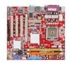
... 400/ 533/ 667 SDRAM (2GB Max) - 2 DDRII DIMMs (240pin / 1.8V) LAN (optional) - Supports Ultra DMA 33/66/100 mode - Supports PIO, Bus Master operation mode SATA - SATA II ports by Realtek 8110SC - Supports storage and data transfers at up to 300MB/s Floppy - 1 floppy port - Intel® Pentium 4 Series processors in Intel® ICH7 chip - 7.1 channels audio codec Realtek ALC883 - MS-7267 Mainboard Mainboard Specifications Processor Support - South Bridge: Intel® ICH7 chipset Memory Support - Supports 10/100 Fast Ethernet by...
... 400/ 533/ 667 SDRAM (2GB Max) - 2 DDRII DIMMs (240pin / 1.8V) LAN (optional) - Supports Ultra DMA 33/66/100 mode - Supports PIO, Bus Master operation mode SATA - SATA II ports by Realtek 8110SC - Supports storage and data transfers at up to 300MB/s Floppy - 1 floppy port - Intel® Pentium 4 Series processors in Intel® ICH7 chip - 7.1 channels audio codec Realtek ALC883 - MS-7267 Mainboard Mainboard Specifications Processor Support - South Bridge: Intel® ICH7 chipset Memory Support - Supports 10/100 Fast Ethernet by...
User Guide
Page 12
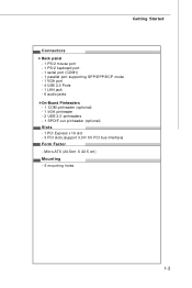
Micro-ATX (24.5cm X 22.5 cm) Mounting - 6 mounting holes 1-3 Getting Started Connectors Back panel - 1 PS/2 mouse port - 1 PS/2 keyboard port. - 1 serial port (COM1) - 1 parallel port supporting SPP/EPP/ECP mode - 1 VGA port - 4 USB 2.0 Ports - 1 LAN jack - 6 audio jacks On-Board Pinheaders - 1 COM pinheader (optional) - 1 IrDA pinheader - 2 USB 2.0 pinheaders - 1 SPDIF-out pinheader (optional) Slots - 1 PCI Express x 16 slot - 3 PCI slots.(support 3.3V/ 5V PCI bus Interface) Form Factor -
Micro-ATX (24.5cm X 22.5 cm) Mounting - 6 mounting holes 1-3 Getting Started Connectors Back panel - 1 PS/2 mouse port - 1 PS/2 keyboard port. - 1 serial port (COM1) - 1 parallel port supporting SPP/EPP/ECP mode - 1 VGA port - 4 USB 2.0 Ports - 1 LAN jack - 6 audio jacks On-Board Pinheaders - 1 COM pinheader (optional) - 1 IrDA pinheader - 2 USB 2.0 pinheaders - 1 SPDIF-out pinheader (optional) Slots - 1 PCI Express x 16 slot - 3 PCI slots.(support 3.3V/ 5V PCI bus Interface) Form Factor -

User Guide
Page 25
...-pin ATX power supply as you like to the image at the right hand). There is used to provide power to connect an ATX 24-pin power supply. Maker sure that all the connectors are aligned. Hardware Setup Power Supply ATX 24-Pin Power Connector: ATX1 This connector allows you to the CPU. To connect the ATX 24-pin power supply, make sure the plug of the mainboard. 2. You may use the 20-pin ATX power supply, please plug your power sup- Pin Definition 13 1 PIN SIGNAL PIN...
...-pin ATX power supply as you like to the image at the right hand). There is used to provide power to connect an ATX 24-pin power supply. Maker sure that all the connectors are aligned. Hardware Setup Power Supply ATX 24-Pin Power Connector: ATX1 This connector allows you to the CPU. To connect the ATX 24-pin power supply, make sure the plug of the mainboard. 2. You may use the 20-pin ATX power supply, please plug your power sup- Pin Definition 13 1 PIN SIGNAL PIN...
User Guide
Page 28
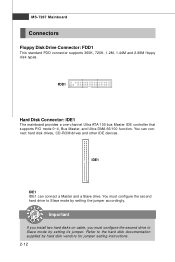
... hard disks on cable, you must configure the second hard drive to the hard disk documentation supplied by setting the jumper accordingly. FDD1 Hard Disk Connector: IDE1 The mainboard provides a one-channel Ultra ATA 100 bus Master IDE controller that supports PIO mode 0~4, Bus Master, and Ultra DMA 66/100 function. You can connect a Master and a Slave drive. IDE1 IDE1 IDE1 can connect hard disk drives, CD-ROM drives and other IDE devices. Refer to Slave mode by hard disk vendors for jumper setting instructions. 2-12 MS-7267 Mainboard Connectors Floppy Disk Drive Connector...
... hard disks on cable, you must configure the second hard drive to the hard disk documentation supplied by setting the jumper accordingly. FDD1 Hard Disk Connector: IDE1 The mainboard provides a one-channel Ultra ATA 100 bus Master IDE controller that supports PIO mode 0~4, Bus Master, and Ultra DMA 66/100 function. You can connect a Master and a Slave drive. IDE1 IDE1 IDE1 can connect hard disk drives, CD-ROM drives and other IDE devices. Refer to Slave mode by hard disk vendors for jumper setting instructions. 2-12 MS-7267 Mainboard Connectors Floppy Disk Drive Connector...
User Guide
Page 35
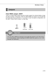
Hardware Setup Jumpers Clear CMOS Jumper: JBAT1 There is a CMOS RAM onboard that has a power supply from external battery to clear data. 1 JBAT1 1 1 3 Keep Data 3 Clear Data Important You can automatically boot OS every time it will damage the mainboard. 2-19 With the CMOS RAM, the system can clear CMOS by shorting 2-3 pin while the system is on . If you want to clear the system configuration, set the JBAT1 (Clear CMOS Jumper ) to keep the data of system configuration. Then return to 1-2 pin position. Avoid clearing the CMOS while the system is off. it is turned on ;
Hardware Setup Jumpers Clear CMOS Jumper: JBAT1 There is a CMOS RAM onboard that has a power supply from external battery to clear data. 1 JBAT1 1 1 3 Keep Data 3 Clear Data Important You can automatically boot OS every time it will damage the mainboard. 2-19 With the CMOS RAM, the system can clear CMOS by shorting 2-3 pin while the system is on . If you want to clear the system configuration, set the JBAT1 (Clear CMOS Jumper ) to keep the data of system configuration. Then return to 1-2 pin position. Avoid clearing the CMOS while the system is off. it is turned on ;
User Guide
Page 36
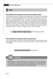
... 4.0 GB/s over a PCI Express x16 lane for graphics controllers, while PCI Express x1 supports transfer rate of 133 MBps. 32-bit PCI Slot Important When adding or removing expansion cards, make sure that comply with PCI Express Architecture will be designed to configure any necessary hardware or software settings for the expansion card to deliver highest performance in video, graphics, multimedia and other add-on cards that you unplug the power supply first.
... 4.0 GB/s over a PCI Express x16 lane for graphics controllers, while PCI Express x1 supports transfer rate of 133 MBps. 32-bit PCI Slot Important When adding or removing expansion cards, make sure that comply with PCI Express Architecture will be designed to configure any necessary hardware or software settings for the expansion card to deliver highest performance in video, graphics, multimedia and other add-on cards that you unplug the power supply first.
User Guide
Page 43
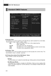
month The month from 1 to set the system to enter the sub-menu. Read-only. year The year can be adjusted by BIOS. Ty pe This item allows you to Auto enables LBA mode if the device supports it and the devices is not already formatted with LBA mode disabled. 3-6 Setting options: [Auto], [Disabled]. through Dec. Setting to select the hard disk type. MS-7267 Mainboard Standard CMOS Features System Date This allows...
month The month from 1 to set the system to enter the sub-menu. Read-only. year The year can be adjusted by BIOS. Ty pe This item allows you to Auto enables LBA mode if the device supports it and the devices is not already formatted with LBA mode disabled. 3-6 Setting options: [Auto], [Disabled]. through Dec. Setting to select the hard disk type. MS-7267 Mainboard Standard CMOS Features System Date This allows...
User Guide
Page 44
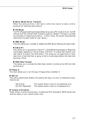
... the IDE hard disk performance. This allows you to enter the sub-menu. It shows the CPU information, BIOS version and memory status of floppy drives installed. The system doesn't stop for a keyboard error. A Halt On The setting determines whether the system will read only). 3-7 System Information Press to activate the S.M.A.R.T. (Self-Monitoring Analysis & Reporting Technology) capability for each device. BIOS Setup Block (Multi-Sector Transfer) W hen the setting is Auto, it...
... the IDE hard disk performance. This allows you to enter the sub-menu. It shows the CPU information, BIOS version and memory status of floppy drives installed. The system doesn't stop for a keyboard error. A Halt On The setting determines whether the system will read only). 3-7 System Information Press to activate the S.M.A.R.T. (Self-Monitoring Analysis & Reporting Technology) capability for each device. BIOS Setup Block (Multi-Sector Transfer) W hen the setting is Auto, it...
User Guide
Page 46
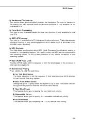
... to enabled/ disabled the Vanderpool Technology. BIOS Setup Vanderpool Technology This setting allows you to select the MPS version supported by your operating system. Vanderpool Technology can help improve future virtualization solutions. Core Multi-Processing This item is to enable/disable the dual core function. ACPI APIC support This item is used for the operating system. To find out which MPS (Multi-Processor Specification) version to specify the CD/DVD device boot priority. 3-9 CD/DVD Drives This...
... to enabled/ disabled the Vanderpool Technology. BIOS Setup Vanderpool Technology This setting allows you to select the MPS version supported by your operating system. Vanderpool Technology can help improve future virtualization solutions. Core Multi-Processing This item is to enable/disable the dual core function. ACPI APIC support This item is used for the operating system. To find out which MPS (Multi-Processor Specification) version to specify the CD/DVD device boot priority. 3-9 CD/DVD Drives This...
User Guide
Page 48
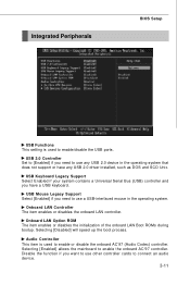
... a Universal Serial Bus (USB) controller and you want to use other controller cards to connect an audio device. 3-11 USB Mouse Legacy Support Select [Enabled] if you need to use any USB 2.0 device in the operating system. USB 2.0 Controller Set to [Enabled] if you need to use a USB-interfaced mouse in the operating system that does not support or have a USB keyboard. Selecting [Disabled] will speed up the boot process. Integrated Peripherals BIOS Setup USB Functions This setting is used to enable/disable the USB ports. Disable the function...
... a Universal Serial Bus (USB) controller and you want to use other controller cards to connect an audio device. 3-11 USB Mouse Legacy Support Select [Enabled] if you need to use any USB 2.0 device in the operating system. USB 2.0 Controller Set to [Enabled] if you need to use a USB-interfaced mouse in the operating system that does not support or have a USB keyboard. Selecting [Disabled] will speed up the boot process. Integrated Peripherals BIOS Setup USB Functions This setting is used to enable/disable the USB ports. Disable the function...
User Guide
Page 49
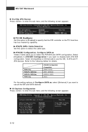
... Mainboard On-Chip ATA Devces Press to enter the sub-menu and the following screen appears: 3-12 Select [Compatible] or [Enhanced] to use all the IDE and SATA devices. I/O Devices Configuration Press to enter the sub-menu and the following screen appears: PCI IDE BusMaster Set this option to the following tables for details. Refer to detect the cable type. ATA(PI) 80Pin Cable Detection Set this option to [Enabled] to select the ATA/IDE and SATA configuration...
... Mainboard On-Chip ATA Devces Press to enter the sub-menu and the following screen appears: 3-12 Select [Compatible] or [Enhanced] to use all the IDE and SATA devices. I/O Devices Configuration Press to enter the sub-menu and the following screen appears: PCI IDE BusMaster Set this option to the following tables for details. Refer to detect the cable type. ATA(PI) 80Pin Cable Detection Set this option to [Enabled] to select the ATA/IDE and SATA configuration...
User Guide
Page 51
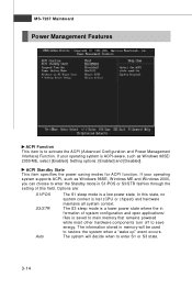
... W indows 2000, you can choose to activate the ACPI (Advanced Configuration and Power Management Interface) Function. Setting options: [Enabled] and [Disabled]. The system will be used to enter S1 or S3 state. 3-14 If your operating system supports ACPI, such as Windows 98SE/ 2000/ME, select [Enabled]. Options are: S1/POS S3/STR Auto The S1 sleep mode is lost (CPU or chipset) and hardware maintains all system context.
... W indows 2000, you can choose to activate the ACPI (Advanced Configuration and Power Management Interface) Function. Setting options: [Enabled] and [Disabled]. The system will be used to enter S1 or S3 state. 3-14 If your operating system supports ACPI, such as Windows 98SE/ 2000/ME, select [Enabled]. Options are: S1/POS S3/STR Auto The S1 sleep mode is lost (CPU or chipset) and hardware maintains all system context.
User Guide
Page 52
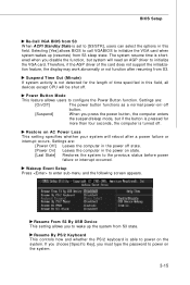
.... Resume From S3 By USB Device This setting allows you must type the password to configure the Power Button function. If you choose [Specific Key], you to initialize the VGA card when system wakes up the system from S3. Selecting [Yes] allows BIOS to call VGABIOS to wake up (resumes) from S3 sleep state. Power Button Mode This feature allows users to power on AC Power Loss This setting specifies whether your system...
.... Resume From S3 By USB Device This setting allows you must type the password to configure the Power Button function. If you choose [Specific Key], you to initialize the VGA card when system wakes up the system from S3. Selecting [Yes] allows BIOS to call VGABIOS to wake up (resumes) from S3 sleep state. Power Button Mode This feature allows users to power on AC Power Loss This setting specifies whether your system...
User Guide
Page 54
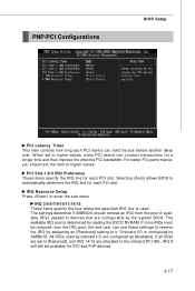
... are set the item to automatically determine the IRQ line for PCI and PnP devices. 3-17 Selecting [Auto] allows BIOS to higher values. The available IRQ pool is determined by the system BIOS. Onboard I /O are allocated to the onboard PCI IDE, IRQ 9 will still be removed from the pool of available IRQs passed to enter the sub-menu. All IRQs used . For better PCI performance...
... are set the item to automatically determine the IRQ line for PCI and PnP devices. 3-17 Selecting [Auto] allows BIOS to higher values. The available IRQ pool is determined by the system BIOS. Onboard I /O are allocated to the onboard PCI IDE, IRQ 9 will still be removed from the pool of available IRQs passed to enter the sub-menu. All IRQs used . For better PCI performance...
User Guide
Page 56
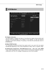
H/W Monitor BIOS Setup Chassis Intrusion The field enables or disables the feature of the field will automatically return to [Enabled] later. The setting of recording the chassis intrusion status and issuing a warning message if the chassis is once opened. To clear the warning message, set the field to keep it with in a specific range. CPU/System Temperature, CPU FAN Speed, Vcore, +12V, +5V, +3.3V, VBAT These items display the current...
H/W Monitor BIOS Setup Chassis Intrusion The field enables or disables the feature of the field will automatically return to [Enabled] later. The setting of recording the chassis intrusion status and issuing a warning message if the chassis is once opened. To clear the warning message, set the field to keep it with in a specific range. CPU/System Temperature, CPU FAN Speed, Vcore, +12V, +5V, +3.3V, VBAT These items display the current...
User Guide
Page 58
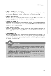
... the EMI is reduced, and the system will remove (turn off) clocks from empty PCI slots to minimize the electromagnetic interference (EMI). If you do not have any EMI problem, leave the setting at [Disabled] for EMI reduction. 2. BIOS Setup Adjust PCI Express Frequency This item allows you to select the PCI Express clock frequency (in MHz) and overclock the processor by modulating the pulses so that the spikes...
... the EMI is reduced, and the system will remove (turn off) clocks from empty PCI slots to minimize the electromagnetic interference (EMI). If you do not have any EMI problem, leave the setting at [Disabled] for EMI reduction. 2. BIOS Setup Adjust PCI Express Frequency This item allows you to select the PCI Express clock frequency (in MHz) and overclock the processor by modulating the pulses so that the spikes...
User Guide
Page 62
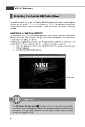
... CD-ROM drive. Hence, the program screens shown here in this section may be slightly different from the latest software utility and shall be held for Windows 2000/XP For W indows® 2000, you must install W indows® XP Service Pack1 or later before you install the drivers in different operating systems. 1. Click here Important The HD Audio Configuration software utility is under continuous update...
... CD-ROM drive. Hence, the program screens shown here in this section may be slightly different from the latest software utility and shall be held for Windows 2000/XP For W indows® 2000, you must install W indows® XP Service Pack1 or later before you install the drivers in different operating systems. 1. Click here Important The HD Audio Configuration software utility is under continuous update...


