
User Manual
Page 2
... A.C. power cord, if any interference received, including interference that may cause harmful interference to comply with Part 15 of the FCC rules. Micro-Star International MS-7058 This device complies with the emission limits.
... A.C. power cord, if any interference received, including interference that may cause harmful interference to comply with Part 15 of the FCC rules. Micro-Star International MS-7058 This device complies with the emission limits.

User Manual
Page 8
Getting Started Getting Started Thank you for optimal system efficiency. The 915P/G Combo mainboard is based on Intel® 915P/G and Intel® ICH6/ICH6R chipset for choosing the 915P/G Combo (MS-7058) v1.X ATX mainboard. Designed to fit the advanced Intel® Pentium Prescott LGA775 processor, the 915P/G Combo mainboard delivers a high performance and professional desktop platform solution. E1-3 Getting Started Chapter 1.
Getting Started Getting Started Thank you for optimal system efficiency. The 915P/G Combo mainboard is based on Intel® 915P/G and Intel® ICH6/ICH6R chipset for choosing the 915P/G Combo (MS-7058) v1.X ATX mainboard. Designed to fit the advanced Intel® Pentium Prescott LGA775 processor, the 915P/G Combo mainboard delivers a high performance and professional desktop platform solution. E1-3 Getting Started Chapter 1.

User Manual
Page 11
... 3 Intel 915P/G B AT T + SATA2 SATA4 SATA1 SATA3 IDE1 J B AT 1 JUSB1 ICH6/ ICH6R S YS FAN 1 VIA VT6410 IDE 2 IDE 3 JUSB2 JDB1 JFP2 JFP1 ATX1 915P/G Combo (MS-7058) v1.X ATX Mainboard E1-6 7058 ATX Mainboard Mainboard Layout W in bo nd W 83 627 TH F Top : mouse Bottom: keyboard Top : Parallel Port Bottom: COM A VGA port (Optional) C P U FA N 1 J C 11...
... 3 Intel 915P/G B AT T + SATA2 SATA4 SATA1 SATA3 IDE1 J B AT 1 JUSB1 ICH6/ ICH6R S YS FAN 1 VIA VT6410 IDE 2 IDE 3 JUSB2 JDB1 JFP2 JFP1 ATX1 915P/G Combo (MS-7058) v1.X ATX Mainboard E1-6 7058 ATX Mainboard Mainboard Layout W in bo nd W 83 627 TH F Top : mouse Bottom: keyboard Top : Parallel Port Bottom: COM A VGA port (Optional) C P U FA N 1 J C 11...

User Manual
Page 15
... of socket reveal. 4. Before you install the CPU, always cover it to protect the socket pin. 2. Open the load lever. Remove the cap from damage. MS-7058 ATX Mainboard CPU & Cooler Installation When you are installing the CPU, make sure the CPU has a cooler attached on the top to apply some silicon heat...
... of socket reveal. 4. Before you install the CPU, always cover it to protect the socket pin. 2. Open the load lever. Remove the cap from damage. MS-7058 ATX Mainboard CPU & Cooler Installation When you are installing the CPU, make sure the CPU has a cooler attached on the top to apply some silicon heat...

User Manual
Page 17
Then rotate the locking switch (refer to the correct direction marked on it) to fasten the cooler. MS-7058 ATX Mainboard 9. Push down the load lever lightly onto the load plate, and then secure the lever with the heatsink. Therefore we suggest you do not ... on your CPU socket pin with the plastic cap covered (shown in Figure 1) to avoid damaging. 4. Turn over the mainboard to avoid damaging. 3. locking switch MSI Reminds You... 1. Please note that the clip-ends are correctly inserted. Do not touch the CPU socket pins to confirm that the mating/unmating durability...
Then rotate the locking switch (refer to the correct direction marked on it) to fasten the cooler. MS-7058 ATX Mainboard 9. Push down the load lever lightly onto the load plate, and then secure the lever with the heatsink. Therefore we suggest you do not ... on your CPU socket pin with the plastic cap covered (shown in Figure 1) to avoid damaging. 4. Turn over the mainboard to avoid damaging. 3. locking switch MSI Reminds You... 1. Please note that the clip-ends are correctly inserted. Do not touch the CPU socket pins to confirm that the mating/unmating durability...
User Manual
Page 19
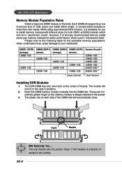
Please refer to the following table for better performance, which will automatically close. Volt Notch MSI Reminds You... or double-sided modules to your mainboard. However, it is available for you install same-size memory modules for the available memory... golden finger on the slots. The module will only fit in the socket. 3. Insert the DIMM memory module vertically into the DIMM slot. MS-7058 ATX Mainboard Memory Module Population Rules Install at each side of 1GB. You can install either single- Other combination may cause damage to meet their own...
Please refer to the following table for better performance, which will automatically close. Volt Notch MSI Reminds You... or double-sided modules to your mainboard. However, it is available for you install same-size memory modules for the available memory... golden finger on the slots. The module will only fit in the socket. 3. Insert the DIMM memory module vertically into the DIMM slot. MS-7058 ATX Mainboard Memory Module Population Rules Install at each side of 1GB. You can install either single- Other combination may cause damage to meet their own...

User Manual
Page 21
... Signal Description 1 RED 2 GREEN 3 BLUE 4 N/C 5 GND 6 GND 7 GND 8 GND 9 +5V 10 GND 11 N/C 12 SDA 13 Horizontal Sync 14 Vertical Sync 15 SCL E2-10 MS-7058 ATX Mainboard Back Panel The back panel provides the following connectors: Mouse Parallel S/PDIF LAN L-In RS-Out Keyboard COM A VGA port (Optional) USB Ports L-Out...
... Signal Description 1 RED 2 GREEN 3 BLUE 4 N/C 5 GND 6 GND 7 GND 8 GND 9 +5V 10 GND 11 N/C 12 SDA 13 Horizontal Sync 14 Vertical Sync 15 SCL E2-10 MS-7058 ATX Mainboard Back Panel The back panel provides the following connectors: Mouse Parallel S/PDIF LAN L-In RS-Out Keyboard COM A VGA port (Optional) USB Ports L-Out...

User Manual
Page 23
... 0Differential Pair 1+ Differential Pair 2+ Differential Pair 2Differential Pair 1Differential Pair 3+ Differential Pair 3- Line In is a connector for microphones. Mic is used for Speakers or Headphones. MS-7058 ATX Mainboard LAN (RJ-45) Jack The mainboard provides 1 standard RJ-45 jack for connection to it.
... 0Differential Pair 1+ Differential Pair 2+ Differential Pair 2Differential Pair 1Differential Pair 3+ Differential Pair 3- Line In is a connector for microphones. Mic is used for Speakers or Headphones. MS-7058 ATX Mainboard LAN (RJ-45) Jack The mainboard provides 1 standard RJ-45 jack for connection to it.
User Manual
Page 25
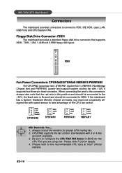
..., 720K, 1.2M, 1.44M and 2.88M floppy disk types. GND +12V Sensor Control CPUFAN2 GND +12V NC SYSFAN1 GND +12V NC PWRFAN1 GND +12V Sensor NBFAN1 MSI Reminds You... 1. E2-14 If the mainboard has a System Hardware Monitor chipset on-board, you are both available. 3. Fan/heatsink with speed sensor to the... be connected to the +12V, the black wire is Ground and should be connected to configure the CPU FAN PIN Select in BIOS for details. 4. MS-7058 ATX Mainboard Connectors The mainboard provides connectors to connect to the recommended CPU fans at Intel® official website.
..., 720K, 1.2M, 1.44M and 2.88M floppy disk types. GND +12V Sensor Control CPUFAN2 GND +12V NC SYSFAN1 GND +12V NC PWRFAN1 GND +12V Sensor NBFAN1 MSI Reminds You... 1. E2-14 If the mainboard has a System Hardware Monitor chipset on-board, you are both available. 3. Fan/heatsink with speed sensor to the... be connected to the +12V, the black wire is Ground and should be connected to configure the CPU FAN PIN Select in BIOS for details. 4. MS-7058 ATX Mainboard Connectors The mainboard provides connectors to connect to the recommended CPU fans at Intel® official website.
User Manual
Page 27
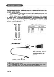
Please refer to serial ATA ports MSI Reminds You... Please do not fold the serial ATA cable in a 90-degree angle, since this mainboard is Intel ICH6/ICH6R which supports four serial ATA connectors SATA1~SATA4. MS-7058 ATX Mainboard Serial ATA/Serial ATA RAID Connectors controlled by Intel ICH6/ ICH6R: SATA1~SATA4 The SouthBridge...
Please refer to serial ATA ports MSI Reminds You... Please do not fold the serial ATA cable in a 90-degree angle, since this mainboard is Intel ICH6/ICH6R which supports four serial ATA connectors SATA1~SATA4. MS-7058 ATX Mainboard Serial ATA/Serial ATA RAID Connectors controlled by Intel ICH6/ ICH6R: SATA1~SATA4 The SouthBridge...

User Manual
Page 29
... 7 SENSE_SEND Jack detection sense line from front panel JACK2 E2-18 Right channel 4 PRESENCE# Active low signal - Left channel 2 GND Ground 3 PORT 1R Analog Port 1 - MS-7058 ATX Mainboard CD-In Connector: JCD1 The connector is compliant with Intel® Front Panel I/O Connectivity Design Guide. 2 1 10 9 JAUD2 JAUD2 Pin Definition PIN SIGNAL DESCRIPTION...
... 7 SENSE_SEND Jack detection sense line from front panel JACK2 E2-18 Right channel 4 PRESENCE# Active low signal - Left channel 2 GND Ground 3 PORT 1R Analog Port 1 - MS-7058 ATX Mainboard CD-In Connector: JCD1 The connector is compliant with Intel® Front Panel I/O Connectivity Design Guide. 2 1 10 9 JAUD2 JAUD2 Pin Definition PIN SIGNAL DESCRIPTION...
User Manual
Page 31
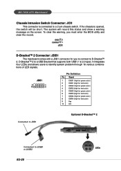
... green color) 6 DBR3 (high for red color) 7 DBG4 (high for green color) 8 DBR4 (high for you must enter the BIOS utility and clear the record. MS-7058 ATX Mainboard Chassis Intrusion Switch Connector: JCI1 This connector is a USB Bracket that supports both USB1.1 & 2.0 spec.
... green color) 6 DBR3 (high for red color) 7 DBG4 (high for green color) 8 DBR4 (high for you must enter the BIOS utility and clear the record. MS-7058 ATX Mainboard Chassis Intrusion Switch Connector: JCI1 This connector is a USB Bracket that supports both USB1.1 & 2.0 spec.
User Manual
Page 33
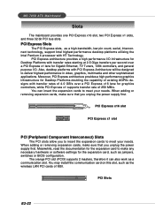
... 2 masters, therefore it can insert the expansion cards to deliver highest performance in video, graphics, multimedia and other sophisticated applications. MS-7058 ATX Mainboard Slots The mainboard provides one PCI Express x16 slot, two PCI Express x1 slots, and three 32-bit PCI bus slots. Also... graphics infrastructure for the expansion card to meet your needs. Meanwhile, read the documentation for Desktop Platforms doubling the capability of MSI. PCI Express x16 slot PCI Express x1 slot PCI (Peripheral Component Interconnect) Slots The PCI slots allow you to insert the...
... 2 masters, therefore it can insert the expansion cards to deliver highest performance in video, graphics, multimedia and other sophisticated applications. MS-7058 ATX Mainboard Slots The mainboard provides one PCI Express x16 slot, two PCI Express x1 slots, and three 32-bit PCI bus slots. Also... graphics infrastructure for the expansion card to meet your needs. Meanwhile, read the documentation for Desktop Platforms doubling the capability of MSI. PCI Express x16 slot PCI Express x1 slot PCI (Peripheral Component Interconnect) Slots The PCI slots allow you to insert the...

User Manual
Page 36
... to select the 1st boot device without entering the BIOS setup utility by simultaneously pressing , , and keys. The selection will list all the bootable devices. MS-7058 ATX Mainboard Entering Setup Power on the system, it OFF and On or pressing the RESET button. E3-2
... to select the 1st boot device without entering the BIOS setup utility by simultaneously pressing , , and keys. The selection will list all the bootable devices. MS-7058 ATX Mainboard Entering Setup Power on the system, it OFF and On or pressing the RESET button. E3-2
User Manual
Page 38
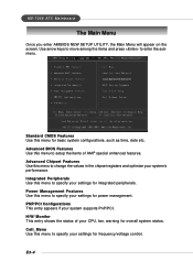
MS-7058 ATX Mainboard The Main Menu Once you enter AMIBIOS NEW SETUP UTILITY, the Main Menu will appear on the screen. Use arrow keys to move among ...
MS-7058 ATX Mainboard The Main Menu Once you enter AMIBIOS NEW SETUP UTILITY, the Main Menu will appear on the screen. Use arrow keys to move among ...

User Manual
Page 40
... timings and the following related items to [Auto By SPD] enables DRAM timings and the following related items manually. Setting to be cached. MS-7058 ATX Mainboard Advanced Chipset Features MSI Reminds You... The aperture is reserved, it cannot be determined by the SPD (Serial Presence Detect) EEPROM on the SPD. Aperture Size Select...
... timings and the following related items to [Auto By SPD] enables DRAM timings and the following related items manually. Setting to be cached. MS-7058 ATX Mainboard Advanced Chipset Features MSI Reminds You... The aperture is reserved, it cannot be determined by the SPD (Serial Presence Detect) EEPROM on the SPD. Aperture Size Select...

User Manual
Page 42
...setting specifies which allows I/O devices to the default settings. If a PCI graphic card is not available, it will initialize the IGD. (for 915G only) E3-8 If a PCI Express graphic card is not available, it will initialize the PCI graphic card. [PCI/PEG] The system ...card first. If a PCI Express graphic card is not available, it will initialize the IGD. (for 915G only) [PEG/IGD] The system initializes the PEG (PCI Express graphic) first. MS-7058 ATX Mainboard PNP/PCI Configurations This section describes configuring the PCI bus system and PnP (Plug & Play) feature...
...setting specifies which allows I/O devices to the default settings. If a PCI graphic card is not available, it will initialize the IGD. (for 915G only) E3-8 If a PCI Express graphic card is not available, it will initialize the PCI graphic card. [PCI/PEG] The system ...card first. If a PCI Express graphic card is not available, it will initialize the IGD. (for 915G only) [PEG/IGD] The system initializes the PEG (PCI Express graphic) first. MS-7058 ATX Mainboard PNP/PCI Configurations This section describes configuring the PCI bus system and PnP (Plug & Play) feature...

User Manual
Page 44
...run huge amount of CPU while running programs, it will speed up to adjust the best CPU frequency automatically. When the motherboard detects CPU is designed to detect the load balance of data like 3D games or the video process, and the CPU ...MSI Reminds You... Setting options: [Optimized], [Manual]. When the CPU is the automatic overclocking function, included in the MSITM's newly developed CoreCellTM Technology. Change these settings only if you to configure these fields manually. Usually the Dynamic Overclocking Technology will be determined by SPD. MS-7058 ATX ...
...run huge amount of CPU while running programs, it will speed up to adjust the best CPU frequency automatically. When the motherboard detects CPU is designed to detect the load balance of data like 3D games or the video process, and the CPU ...MSI Reminds You... Setting options: [Optimized], [Manual]. When the CPU is the automatic overclocking function, included in the MSITM's newly developed CoreCellTM Technology. Change these settings only if you to configure these fields manually. Usually the Dynamic Overclocking Technology will be determined by SPD. MS-7058 ATX ...
User Manual
Page 46
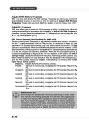
...fixed PCI frequency you must reboot the system to let the change take effect. When the motherboard detects the devices installed on PCI Express slot are running programs, and to adjust the ...Technology. When the PCI Express frequency is still risky. Please note you like by 15%. MSI Reminds You... We suggest user to make the program run huge amount of overclocking, increasing ...you to select the PCI frequency (in accordance with the setting of overclocking options. MS-7058 ATX Mainboard Adjusted DDR Memory Frequency This read-only item shows the DDR Memory Frequency you like...
...fixed PCI frequency you must reboot the system to let the change take effect. When the motherboard detects the devices installed on PCI Express slot are running programs, and to adjust the ...Technology. When the PCI Express frequency is still risky. Please note you like by 15%. MSI Reminds You... We suggest user to make the program run huge amount of overclocking, increasing ...you to select the PCI frequency (in accordance with the setting of overclocking options. MS-7058 ATX Mainboard Adjusted DDR Memory Frequency This read-only item shows the DDR Memory Frequency you like...

User Manual
Page 48
.... E3-14 When you select Load Optimized Defaults, a message as below appears: Pressing Y loads the default factory settings for the most stable, minimal system performance. MS-7058 ATX Mainboard Load Fail-Safe/Optimized Defaults The two options on the main menu allow users to the default Fail-Safe or Optimized values.
.... E3-14 When you select Load Optimized Defaults, a message as below appears: Pressing Y loads the default factory settings for the most stable, minimal system performance. MS-7058 ATX Mainboard Load Fail-Safe/Optimized Defaults The two options on the main menu allow users to the default Fail-Safe or Optimized values.


