User Guide
Page 4
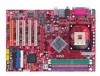
...Do not cover the openings. 6. All cautions and warnings on the enclosure are for technical guide, BIOS updates, driver updates, and other information: http://www.msi.com.tw & http://www.msi. Do not leave this equipment on a reliable flat surface before inserting any add-on it up...following help resources for future reference. 3. h The equipment has obvious sign of explosion if battery is damaged. iv h Visit the MSI homepage & FAQ site for air convection hence protects the equip- Technical Support If a problem arises with the same or equivalent type ...
...Do not cover the openings. 6. All cautions and warnings on the enclosure are for technical guide, BIOS updates, driver updates, and other information: http://www.msi.com.tw & http://www.msi. Do not leave this equipment on a reliable flat surface before inserting any add-on it up...following help resources for future reference. 3. h The equipment has obvious sign of explosion if battery is damaged. iv h Visit the MSI homepage & FAQ site for air convection hence protects the equip- Technical Support If a problem arises with the same or equivalent type ...

User Guide
Page 6
... Device 3-2 Control Keys 3-3 Getting Help 3-3 Main Menu 3-3 Default Settings 3-3 The Main Menu 3-4 Standard CMOS Features 3-6 Advanced BIOS Features 3-8 Advanced Chipset Features 3-11 Power Management Features 3-13 PNP/PCI Configurations 3-16 Integrated Peripherals 3-19 PC Health Status 3-23... Frequency/Voltage Control 3-24 Set Supervisor/User Password 3-27 Load High Performance/BIOS Setup Defaults 3-28 vi CD-In Connector: CD1 2-14 ATA100 Hard Disk Connectors: IDE1 & IDE2 2-15 Front USB Connectors: JUSB2...
... Device 3-2 Control Keys 3-3 Getting Help 3-3 Main Menu 3-3 Default Settings 3-3 The Main Menu 3-4 Standard CMOS Features 3-6 Advanced BIOS Features 3-8 Advanced Chipset Features 3-11 Power Management Features 3-13 PNP/PCI Configurations 3-16 Integrated Peripherals 3-19 PC Health Status 3-23... Frequency/Voltage Control 3-24 Set Supervisor/User Password 3-27 Load High Performance/BIOS Setup Defaults 3-28 vi CD-In Connector: CD1 2-14 ATA100 Hard Disk Connectors: IDE1 & IDE2 2-15 Front USB Connectors: JUSB2...
User Guide
Page 9
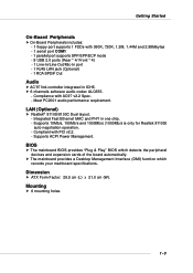
.../8100C Dual layout. - h 6 channels software audio codec ALC655. - Integrated Fast Ethernet MAC and PHY in ICH5. Dimension h ATX Form Factor: 29.5 cm (L) x 21.0 cm (W). Supports ACPI Power Management. BIOS h The mainboard BIOS provides "Plug & Play" BIOS which records your mainboard specifications. Supports 10Mb/s, 100Mb/s and 1000Mb/s (1000Mb/s is only for Realtek 8110S) auto-negotiation...
.../8100C Dual layout. - h 6 channels software audio codec ALC655. - Integrated Fast Ethernet MAC and PHY in ICH5. Dimension h ATX Form Factor: 29.5 cm (L) x 21.0 cm (W). Supports ACPI Power Management. BIOS h The mainboard BIOS provides "Plug & Play" BIOS which records your mainboard specifications. Supports 10Mb/s, 100Mb/s and 1000Mb/s (1000Mb/s is only for Realtek 8110S) auto-negotiation...
User Guide
Page 10
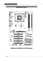
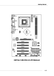
I n M:Line-Out B:Mic JPW1 ATX Power Supply Intel 865PE chipset DIMM 1 DIMM 2 DIMM 3 Winb ond W83627THF BIOS AGP Slot PCI Slot 1 Realtek 8110S/8100C PCI Slot 2 PCI Slot 3 CD1 Codec JSP1 PCI Slot 4 PCI Slot 5 JAUD1 JDB1 ICH 5 S ATA 2 S ATA 1 IDE 2 IDE 1 SYSFAN1 BATT + USB2 USB3 FDD1 J B AT 1 JFP1 JFP2 865PE Neo2-V (MS-6788 v2.X) ATX Mainboard 1-4 MS-6788 ATX Mainboard Mainboard Layout Top : mouse Bottom: keyboard CP UFAN1 T:SP DIF Out B:USB ports T:LAN jack (Optional) B:USB ports T: L i n e -
I n M:Line-Out B:Mic JPW1 ATX Power Supply Intel 865PE chipset DIMM 1 DIMM 2 DIMM 3 Winb ond W83627THF BIOS AGP Slot PCI Slot 1 Realtek 8110S/8100C PCI Slot 2 PCI Slot 3 CD1 Codec JSP1 PCI Slot 4 PCI Slot 5 JAUD1 JDB1 ICH 5 S ATA 2 S ATA 1 IDE 2 IDE 1 SYSFAN1 BATT + USB2 USB3 FDD1 J B AT 1 JFP1 JFP2 865PE Neo2-V (MS-6788 v2.X) ATX Mainboard 1-4 MS-6788 ATX Mainboard Mainboard Layout Top : mouse Bottom: keyboard CP UFAN1 T:SP DIF Out B:USB ports T:LAN jack (Optional) B:USB ports T: L i n e -
User Guide
Page 11
Getting Started Top : mouse Bottom: keyboard CP UFAN1 T:SP DIF Out B:USB ports T:LAN jack (Optional) B:USB ports T: L i n e - I n M:Line-Out B:Mic JPW1 ATX Power Supply Intel 848P chipset DIMM 1 DIMM 2 Winb ond W83627THF BIOS AGP Slot PCI Slot 1 Realtek 8110S/8100C PCI Slot 2 PCI Slot 3 CD1 Codec JSP1 PCI Slot 4 PCI Slot 5 JAUD1 JDB1 ICH 5 S ATA 2 S ATA 1 IDE 2 IDE 1 SYSFAN 1 BATT + USB2 USB3 FDD1 J B AT 1 JFP1 JFP2 848P Neo-V (MS-6788 v2.X) ATX Mainboard 1-5
Getting Started Top : mouse Bottom: keyboard CP UFAN1 T:SP DIF Out B:USB ports T:LAN jack (Optional) B:USB ports T: L i n e - I n M:Line-Out B:Mic JPW1 ATX Power Supply Intel 848P chipset DIMM 1 DIMM 2 Winb ond W83627THF BIOS AGP Slot PCI Slot 1 Realtek 8110S/8100C PCI Slot 2 PCI Slot 3 CD1 Codec JSP1 PCI Slot 4 PCI Slot 5 JAUD1 JDB1 ICH 5 S ATA 2 S ATA 1 IDE 2 IDE 1 SYSFAN 1 BATT + USB2 USB3 FDD1 J B AT 1 JFP1 JFP2 848P Neo-V (MS-6788 v2.X) ATX Mainboard 1-5
User Guide
Page 33
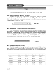
... AGP graphics card. AGP Slot PCI (Peripheral Component Interconnect) Slots The PCI slots allow you to meet your needs. MS-6788 ATX Mainboard Slots The motherboard provides one AGP slot and five 32-bit PCI bus slots. The orange PCI slot (PCI5) also works as a communcation slot...demands of interrupt request line and pronounced I-R-Q, are typically connected to the PCI bus INT A# ~ INT D# pins as jumpers, switches or BIOS configuration. When adding or removing expansion cards, make any necessary hardware or software settings for the expansion card to directly access main memory. ...
... AGP graphics card. AGP Slot PCI (Peripheral Component Interconnect) Slots The PCI slots allow you to meet your needs. MS-6788 ATX Mainboard Slots The motherboard provides one AGP slot and five 32-bit PCI bus slots. The orange PCI slot (PCI5) also works as a communcation slot...demands of interrupt request line and pronounced I-R-Q, are typically connected to the PCI bus INT A# ~ INT D# pins as jumpers, switches or BIOS configuration. When adding or removing expansion cards, make any necessary hardware or software settings for the expansion card to directly access main memory. ...
User Guide
Page 34
...line appearing after the memory counting. Therefore, the description may need to run the Setup program when: ” An error message appears on the BIOS Setup program and allows you to run SETUP. ” You want to configure the system for reference only. 2. W=AWARD(R) 2nd - 5th ...digit refers to the model number. 6th - 7th digit refers to BIOS maker as A=AMI(R); The items under continuous update for customized features. MSI Reminds You... 1. BIOS Setup Chapter 3. You may be slightly different from the latest...
...line appearing after the memory counting. Therefore, the description may need to run the Setup program when: ” An error message appears on the BIOS Setup program and allows you to run SETUP. ” You want to configure the system for reference only. 2. W=AWARD(R) 2nd - 5th ...digit refers to the model number. 6th - 7th digit refers to BIOS maker as A=AMI(R); The items under continuous update for customized features. MSI Reminds You... 1. BIOS Setup Chapter 3. You may be slightly different from the latest...
User Guide
Page 35
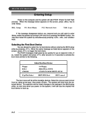
... POST (Power On Self Test) process. When the message below appears on the screen, press key to select the 1st boot device without entering the BIOS setup utility by pressing . The POST messages might pass by too quickly for you still wish to boot up. 3-2 MS-6788... ATX Mainboard Entering Setup Power on the computer and the system will boot from by using arrow keys, then press . DEL: Setup F11: Boot Menu F12: ...
... POST (Power On Self Test) process. When the message below appears on the screen, press key to select the 1st boot device without entering the BIOS setup utility by pressing . The POST messages might pass by too quickly for you still wish to boot up. 3-2 MS-6788... ATX Mainboard Entering Setup Power on the computer and the system will boot from by using arrow keys, then press . DEL: Setup F11: Boot Menu F12: ...
User Guide
Page 36
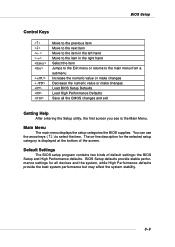
...↑↓ ) to the main menu from a submenu Increase the numeric value or make changes Decrease the numeric value or make changes Load BIOS Setup Defaults Load High Performance Defaults Save all devices and the system, while High Performance defaults provide the best system performance but may affect the... system stability. 3-3 BIOS Setup Control Keys Enter> Move to the previous item Move to the next item Move to the item in the left hand Move to...
...↑↓ ) to the main menu from a submenu Increase the numeric value or make changes Decrease the numeric value or make changes Load BIOS Setup Defaults Load High Performance Defaults Save all devices and the system, while High Performance defaults provide the best system performance but may affect the... system stability. 3-3 BIOS Setup Control Keys Enter> Move to the previous item Move to the next item Move to the item in the left hand Move to...
User Guide
Page 37
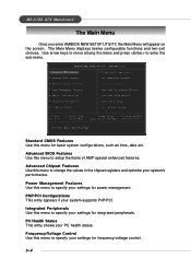
...specify your settings for basic system configurations, such as time, date etc. PNP/PCI Configurations This entry appears if your PC health status. Advanced BIOS Features Use this menu to specify your settings for integrated peripherals. Frequency/Voltage Control Use this menu to enter the sub-menu. Use arrow keys.... Advanced Chipset Features Use this menu to change the values in the chipset registers and optimize your settings for frequency/voltage control. 3-4 MS-6788 ATX Mainboard The Main Menu Once you enter AMIBIOS NEW SETUP UTILITY, the Main Menu will appear on the screen.
...specify your settings for basic system configurations, such as time, date etc. PNP/PCI Configurations This entry appears if your PC health status. Advanced BIOS Features Use this menu to specify your settings for integrated peripherals. Frequency/Voltage Control Use this menu to enter the sub-menu. Use arrow keys.... Advanced Chipset Features Use this menu to change the values in the chipset registers and optimize your settings for frequency/voltage control. 3-4 MS-6788 ATX Mainboard The Main Menu Once you enter AMIBIOS NEW SETUP UTILITY, the Main Menu will appear on the screen.
User Guide
Page 38
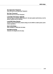
BIOS Setup Set Supervisor Password Use this menu to load the BIOS values for stable system performance operations. Load High Performance Defaults Use this menu to load factory default settings into the BIOS for the best system performance, but the system stability may be affected. Save & Exit Setup Save changes to set Supervisor Password. Set User Password Use this menu to set User Password. Exit Without Saving Abandon all changes and exit setup. 3-5 Load BIOS Setup Defaults Use this menu to CMOS and exit setup.
BIOS Setup Set Supervisor Password Use this menu to load the BIOS values for stable system performance operations. Load High Performance Defaults Use this menu to load factory default settings into the BIOS for the best system performance, but the system stability may be affected. Save & Exit Setup Save changes to set Supervisor Password. Set User Password Use this menu to set User Password. Exit Without Saving Abandon all changes and exit setup. 3-5 Load BIOS Setup Defaults Use this menu to CMOS and exit setup.
User Guide
Page 39
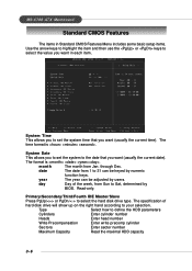
... Capacity Read the maximal HDD capacity 3-6 System Time This allows you want (usually the current date). through Dec. year The year can be adjusted by BIOS. day Day of hard disk drive will show up on the right hand according to select the hard disk drive type. MS-6788... ATX Mainboard Standard CMOS Features The items in each item. month The month from Sun to select the value you to 31 can be keyed by ...
... Capacity Read the maximal HDD capacity 3-6 System Time This allows you want (usually the current date). through Dec. year The year can be adjusted by BIOS. day Day of hard disk drive will show up on the right hand according to select the hard disk drive type. MS-6788... ATX Mainboard Standard CMOS Features The items in each item. month The month from Sun to select the value you to 31 can be keyed by ...

User Guide
Page 40
Available options: [None], [360K, 5.25 in.], [1.2M, 5.25 in.], [720K, 3.5 in.], [1.44M, 3.5 in.], [2.88M, 3.5 in.]. 3-7 BIOS Setup LBA Mode Block Mode Fast Programmed I/O Modes 32 Bit Transfer Mode Select [Auto] for a hard disk > 512 MB under Windows and DOS, or [Disabled] under Netware and UNIX Select [Auto] to enhance the hard disk performance Select [Auto] to enhance hard disk performance by optimizing the hard disk timing Enable 32 bit to maximize the IDE hard disk data transfer rate Floppy Drive A: This item allows you to set the type of the floppy drive installed.
Available options: [None], [360K, 5.25 in.], [1.2M, 5.25 in.], [720K, 3.5 in.], [1.44M, 3.5 in.], [2.88M, 3.5 in.]. 3-7 BIOS Setup LBA Mode Block Mode Fast Programmed I/O Modes 32 Bit Transfer Mode Select [Auto] for a hard disk > 512 MB under Windows and DOS, or [Disabled] under Netware and UNIX Select [Auto] to enhance the hard disk performance Select [Auto] to enhance hard disk performance by optimizing the hard disk timing Enable 32 bit to maximize the IDE hard disk data transfer rate Floppy Drive A: This item allows you to set the type of the floppy drive installed.
User Guide
Page 41
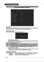
...[Disabled] Shows the POST messages at boot. 3-8 Full Screen LOGO Show This item enables you to set the sequence of boot devices where BIOS attempts to boot within 5 seconds since it will skip some check items. Available options: [Enabled], [Disabled]. Boot Device Select Press to enter...up. For example, if you have installed. Settings are: [Enabled] Shows a still image (logo) on the bootup screen. MSI Reminds You... MS-6788 ATX Mainboard Advanced BIOS Features Quick Boot Setting the item to [Enabled] allows the system to load the disk operating system. . Try Other Boot ...
...[Disabled] Shows the POST messages at boot. 3-8 Full Screen LOGO Show This item enables you to set the sequence of boot devices where BIOS attempts to boot within 5 seconds since it will skip some check items. Available options: [Enabled], [Disabled]. Boot Device Select Press to enter...up. For example, if you have installed. Settings are: [Enabled] Shows a still image (logo) on the bootup screen. MSI Reminds You... MS-6788 ATX Mainboard Advanced BIOS Features Quick Boot Setting the item to [Enabled] allows the system to load the disk operating system. . Try Other Boot ...
User Guide
Page 42
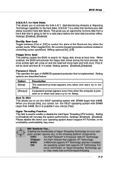
...Monitoring Analysis & Reporting Technology) capability for floppy disk drives at boot time. MSI Reminds You... This gives you to a safe place before the hard disk becomes offline. When enabled, the BIOS will activate the floppy disk drives during the boot process: the drive activity... *CPU: An Intel® Pentium® 4 Processor with HT Technology; *Chipset: An Intel® Chipset that supports HT Technology; *BIOS: A BIOS that supports HT Technology. Setting options: [Enabled], [Disabled]. But it enabled; *OS: An operating system that supports HT Technology and has...
...Monitoring Analysis & Reporting Technology) capability for floppy disk drives at boot time. MSI Reminds You... This gives you to a safe place before the hard disk becomes offline. When enabled, the BIOS will activate the floppy disk drives during the boot process: the drive activity... *CPU: An Intel® Pentium® 4 Processor with HT Technology; *Chipset: An Intel® Chipset that supports HT Technology; *BIOS: A BIOS that supports HT Technology. Setting options: [Enabled], [Disabled]. But it enabled; *OS: An operating system that supports HT Technology and has...
User Guide
Page 43
...of specified ROM are copied to this memory area, a system error may result. Settings: [Enabled], [Disabled]. System BIOS Cacheable Selecting [Enabled] allows caching of the system BIOS ROM at F0000h-FFFFFh, resulting in APIC mode. Settings: [1.4], [1.1]. When the CPU requests data, the system transfers the... requested data from cache memory. 3-10 However, if any program writes to RAM for the system. Settings are handled. MS-6788 ATX Mainboard MPS ...
...of specified ROM are copied to this memory area, a system error may result. Settings: [Enabled], [Disabled]. System BIOS Cacheable Selecting [Enabled] allows caching of the system BIOS ROM at F0000h-FFFFFh, resulting in APIC mode. Settings: [1.4], [1.1]. When the CPU requests data, the system transfers the... requested data from cache memory. 3-10 However, if any program writes to RAM for the system. Settings are handled. MS-6788 ATX Mainboard MPS ...
User Guide
Page 44
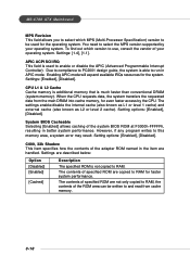
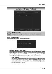
BIOS Setup Advanced Chipset Features MSI Reminds You... Press and to be determined by the SPD (Serial Presence Detect) EEPROM on the SPD. Setting to [Enabled] enables the following fields automatically ... the system performance the most while [2.5 Clocks] provides the most stable performance. 3-11 Configure SDRAM Timing by SPD Selects whether DRAM timing is controlled by BIOS based on the configurations on the DRAM module. CAS# Latency This controls the timing delay (in clock cycles) before SDRAM starts a read command after receiving...
BIOS Setup Advanced Chipset Features MSI Reminds You... Press and to be determined by the SPD (Serial Presence Detect) EEPROM on the SPD. Setting to [Enabled] enables the following fields automatically ... the system performance the most while [2.5 Clocks] provides the most stable performance. 3-11 Configure SDRAM Timing by SPD Selects whether DRAM timing is controlled by BIOS based on the configurations on the DRAM module. CAS# Latency This controls the timing delay (in clock cycles) before SDRAM starts a read command after receiving...
User Guide
Page 46
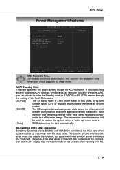
...and Windows 2000, you disable the function, but system will be used to initialize the VGA card when system wakes up " event occurs. [Auto] BIOS determines the best automatically. The system resume time is a low power state. In this state, no system context is lost (CPU or chipset) ...ACPI Standby State This item specifies the power saving modes for ACPI function. nents turn off to initialize the VGA card. BIOS Setup Power Management Features MSI Reminds You... If your BIOS supports S3 sleep mode. The information stored in S1 (POS) or S3 (STR) fashion through the setting of this...
...and Windows 2000, you disable the function, but system will be used to initialize the VGA card when system wakes up " event occurs. [Auto] BIOS determines the best automatically. The system resume time is a low power state. In this state, no system context is lost (CPU or chipset) ...ACPI Standby State This item specifies the power saving modes for ACPI function. nents turn off to initialize the VGA card. BIOS Setup Power Management Features MSI Reminds You... If your BIOS supports S3 sleep mode. The information stored in S1 (POS) or S3 (STR) fashion through the setting of this...
User Guide
Page 47
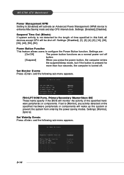
... is pressed for the length of the specified hardware peripherals or components. Set Monitor Events Press and the following sub-menu appears. 3-14 MS-6788 ATX Mainboard Power Management/APM Setting to [Enabled] will be shut off. Settings: [Enabled], [Disabled]. Settings: [Disabled], [1], [2], [4], [8], [10], [20], [30], [40], [50...], [60]. FDC/LPT/COM Ports, Primary/Secondary Master/Slave IDE These items specify if the BIOS will wake up the system or prevent the system from entering the power saving modes.
... is pressed for the length of the specified hardware peripherals or components. Set Monitor Events Press and the following sub-menu appears. 3-14 MS-6788 ATX Mainboard Power Management/APM Setting to [Enabled] will be shut off. Settings: [Enabled], [Disabled]. Settings: [Disabled], [1], [2], [4], [8], [10], [20], [30], [40], [50...], [60]. FDC/LPT/COM Ports, Primary/Secondary Master/Slave IDE These items specify if the BIOS will wake up the system or prevent the system from entering the power saving modes.
User Guide
Page 48
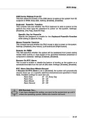
... password to enable for each item are: Alarm Date 01 ~ 31, Every Day Alarm Hour 00 ~ 23 Alarm Minute 00 ~ 59 Alarm Second 00 ~ 59 MSI Reminds You... Settings: [Disabled], [Any Action], [Left-button] and [Right-button]. Settings: [Enabled], [Disabled]. Settings: [Enabled], [Disabled]. Setting: [Enabled], [Disabled]. Settings: [...the soft off (S5) state. RTC Alarm Date/Hour/Minute/Second If Resume On RTC Alarm is used to RAM) sleep state. BIOS Setup USB Device Wakeup From S3 This item allows the activity of the USB device to wake up the system from S3 (suspend ...
... password to enable for each item are: Alarm Date 01 ~ 31, Every Day Alarm Hour 00 ~ 23 Alarm Minute 00 ~ 59 Alarm Second 00 ~ 59 MSI Reminds You... Settings: [Disabled], [Any Action], [Left-button] and [Right-button]. Settings: [Enabled], [Disabled]. Settings: [Enabled], [Disabled]. Setting: [Enabled], [Disabled]. Settings: [...the soft off (S5) state. RTC Alarm Date/Hour/Minute/Second If Resume On RTC Alarm is used to RAM) sleep state. BIOS Setup USB Device Wakeup From S3 This item allows the activity of the USB device to wake up the system from S3 (suspend ...


