
HALO 20 20 and 24 Installation Manual
Page 3
...: (1) this device must Preface | Halo20, 20+ and 24 Dome Radars Installation Manual | 3 Warning: The user is available in accordance with CE under RED Directive 2014/53/EU. Please contact your display or system: www.lowrance.com www.simrad-yachting.com www.bandg.com Compliance statement Europe This equipment complies with provided instructions, and it must accept any...
...: (1) this device must Preface | Halo20, 20+ and 24 Dome Radars Installation Manual | 3 Warning: The user is available in accordance with CE under RED Directive 2014/53/EU. Please contact your display or system: www.lowrance.com www.simrad-yachting.com www.bandg.com Compliance statement Europe This equipment complies with provided instructions, and it must accept any...
HALO 20 20 and 24 Installation Manual
Page 4
...to comply with the limits for a Class B digital device, pursuant to other users, the antenna type and its gain should be so chosen that the equivalent isotropically radiated power (e.i.r.p.) is connected • Consult the dealer or an experienced technician for help ... de l'émetteur. 4 | Preface | Halo20, 20+ and 24 Dome Radars Installation Manual Le présent appareil est conforme aux CNR d'Industrie Canada applicables aux appareils radio exempts de licence. This equipment generates, uses and can be determined by turning the equipment off and on a circuit different ...
...to comply with the limits for a Class B digital device, pursuant to other users, the antenna type and its gain should be so chosen that the equivalent isotropically radiated power (e.i.r.p.) is connected • Consult the dealer or an experienced technician for help ... de l'émetteur. 4 | Preface | Halo20, 20+ and 24 Dome Radars Installation Manual Le présent appareil est conforme aux CNR d'Industrie Canada applicables aux appareils radio exempts de licence. This equipment generates, uses and can be determined by turning the equipment off and on a circuit different ...
HALO 20 20 and 24 Installation Manual
Page 5
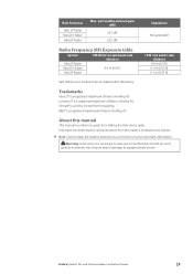
...+ and 24 Dome Radars Installation Manual | 5 Important text that they should proceed carefully to prevent risk of Navico Holding AS. Lowrance® is a reference guide for installing the Halo dome radar. Halo Antennas Halo 20 Radar Halo20+ Radar Halo24 Radar Max. permissible antenna gain (dBi) 22.5 dBi 23.5 dBi Impedance Not applicable Radio Frequency (RF) Exposure table System Halo20 Radar Halo20+ Radar Halo24 Radar 100 W/m2 occupational...
...+ and 24 Dome Radars Installation Manual | 5 Important text that they should proceed carefully to prevent risk of Navico Holding AS. Lowrance® is a reference guide for installing the Halo dome radar. Halo Antennas Halo 20 Radar Halo20+ Radar Halo24 Radar Max. permissible antenna gain (dBi) 22.5 dBi 23.5 dBi Impedance Not applicable Radio Frequency (RF) Exposure table System Halo20 Radar Halo20+ Radar Halo24 Radar 100 W/m2 occupational...
HALO 20 20 and 24 Installation Manual
Page 6
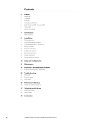
... roof mounting 13 Wiring overview 14 Scanner connection 15 Installing the scanner 16 Ethernet connection 18 Power connection 19 Power control connection 20 Setup and configuration 21 Maintenance 22 Replacing a Broadband 3G/4G Radar 22 RI-10 Radar interface box and wiring 23 Troubleshooting 23 Status LED 23 Error messages 24 Error codes 25 Dimensional drawings 25 Halo dome radar dimensions 27 Technical specifications 27 Halo20/20+ Radar...
... roof mounting 13 Wiring overview 14 Scanner connection 15 Installing the scanner 16 Ethernet connection 18 Power connection 19 Power control connection 20 Setup and configuration 21 Maintenance 22 Replacing a Broadband 3G/4G Radar 22 RI-10 Radar interface box and wiring 23 Troubleshooting 23 Status LED 23 Error messages 24 Error codes 25 Dimensional drawings 25 Halo dome radar dimensions 27 Technical specifications 27 Halo20/20+ Radar...
HALO 20 20 and 24 Installation Manual
Page 7
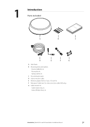
1 Introduction Parts included A B bbbbaaaannnnddddgggg....ccccoooommmm EEEENNNNGGGGLLLLIIIISSSSHHHHIIIInnnnssssttttaaaallllllllaaaattttiiiioooonnnn MMMMaaaannnnuuuuaaaallll C D E F G A Halo Radar B Mounting bolts and washers Hex bolt (M8x30), 4x Flat washer, 4x Spring washer, 4x C Documentation pack D Interconnection cable E Ethernet adapter RJ45 to 5-pin, 1.5m (4.9 ft) F Waterproof cable boot for interconnection cable RJ45 plug G Cable retainer kit Cable retainer clip, 2x Screw (Phillips drive), 4x Introduction | Halo20, 20+ and 24 Dome Radars Installation Manual | 7
1 Introduction Parts included A B bbbbaaaannnnddddgggg....ccccoooommmm EEEENNNNGGGGLLLLIIIISSSSHHHHIIIInnnnssssttttaaaallllllllaaaattttiiiioooonnnn MMMMaaaannnnuuuuaaaallll C D E F G A Halo Radar B Mounting bolts and washers Hex bolt (M8x30), 4x Flat washer, 4x Spring washer, 4x C Documentation pack D Interconnection cable E Ethernet adapter RJ45 to 5-pin, 1.5m (4.9 ft) F Waterproof cable boot for interconnection cable RJ45 plug G Cable retainer kit Cable retainer clip, 2x Screw (Phillips drive), 4x Introduction | Halo20, 20+ and 24 Dome Radars Installation Manual | 7
HALO 20 20 and 24 Installation Manual
Page 8
... all wiring connections if extending or shortening the cables • use the appropriate length of the power supply is factory sealed. Removing the cover will void the factory warranty. ¼ Note: If replacing an already installed Broadband 3G/4G Radar, refer to turn electrical power off. 2 Installation ¼ Note: The Halo Radar is compatible with the unit. 8 | Installation | Halo20, 20+ and 24 Dome Radars Installation Manual
... all wiring connections if extending or shortening the cables • use the appropriate length of the power supply is factory sealed. Removing the cover will void the factory warranty. ¼ Note: If replacing an already installed Broadband 3G/4G Radar, refer to turn electrical power off. 2 Installation ¼ Note: The Halo Radar is compatible with the unit. 8 | Installation | Halo20, 20+ and 24 Dome Radars Installation Manual
HALO 20 20 and 24 Installation Manual
Page 9
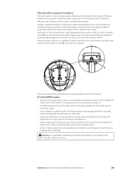
... other equipment such as direction finders, VHF antennas, GPS equipment, as it may damage the dome. Refer to "Considerations for the majority of the radar • close to lamps or exhaust outlets. If you think you mount the scanner on the location, consider the following: A higher installation position increases the radar ranging distance, but it will...
... other equipment such as direction finders, VHF antennas, GPS equipment, as it may damage the dome. Refer to "Considerations for the majority of the radar • close to lamps or exhaust outlets. If you think you mount the scanner on the location, consider the following: A higher installation position increases the radar ranging distance, but it will...
HALO 20 20 and 24 Installation Manual
Page 10
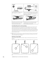
...Use the following illustrations to tilt the scanner angle down at the front. Minimum distance to install near the ships compass is constructed of any time the Halo Radar is a guide to determine scanner height in relation to the furthest forward corner of metal you must be severely impaired. If installed on power boats that the mounting...the height of the hard top. Installation | Halo20, 20+ and 24 Dome Radars Installation Manual A pulse radar must elevate the radar so that the vertical radar beam extends 25° above and below horizontal for Halo20/20+ and 22° above ...
...Use the following illustrations to tilt the scanner angle down at the front. Minimum distance to install near the ships compass is constructed of any time the Halo Radar is a guide to determine scanner height in relation to the furthest forward corner of metal you must be severely impaired. If installed on power boats that the mounting...the height of the hard top. Installation | Halo20, 20+ and 24 Dome Radars Installation Manual A pulse radar must elevate the radar so that the vertical radar beam extends 25° above and below horizontal for Halo20/20+ and 22° above ...
HALO 20 20 and 24 Installation Manual
Page 11
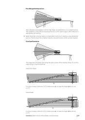
... is either reflected or absorbed by 45 mm (1.77"). Installation | Halo20, 20+ and 24 Dome Radars Installation Manual | 11 Halo20/20+ Radar 3.0 m2.80 m2.60 m2.40 m2.20 m2.00 m1.80 m1.60 m1.40 m1.20 m1.00 m0.80 m 0.55 m A 0 mm 60 ....5° 11° The image above illustrates that the beam has complete clearance, else performance will be severely impaired. Possible performance loss 50% of beam power 50% of beam power Above illustrates an installation with the Halo Radar mounted directly on to clear the hard top.
... is either reflected or absorbed by 45 mm (1.77"). Installation | Halo20, 20+ and 24 Dome Radars Installation Manual | 11 Halo20/20+ Radar 3.0 m2.80 m2.60 m2.40 m2.20 m2.00 m1.80 m1.60 m1.40 m1.20 m1.00 m0.80 m 0.55 m A 0 mm 60 ....5° 11° The image above illustrates that the beam has complete clearance, else performance will be severely impaired. Possible performance loss 50% of beam power 50% of beam power Above illustrates an installation with the Halo Radar mounted directly on to clear the hard top.
HALO 20 20 and 24 Installation Manual
Page 13
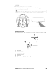
... switch. Halo light ¼ Note: Only available for use in your local boating regulations before turning the blue accent lights ON. Refer to 5-pin (optional) Installation | Halo20, 20+ and 24 Dome Radars Installation Manual | 13 Please check your boating location. A B F D C E A Halo Radar B Scanner connector C Interconnection cable D Ethernet connector E Power wires F Ethernet adapter RJ45 to "Setup and configuration" on page 20. ! The Halo...
... switch. Halo light ¼ Note: Only available for use in your local boating regulations before turning the blue accent lights ON. Refer to 5-pin (optional) Installation | Halo20, 20+ and 24 Dome Radars Installation Manual | 13 Please check your boating location. A B F D C E A Halo Radar B Scanner connector C Interconnection cable D Ethernet connector E Power wires F Ethernet adapter RJ45 to "Setup and configuration" on page 20. ! The Halo...

HALO 20 20 and 24 Installation Manual
Page 14
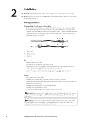
... the retainer nearest the interconnection cable socket. ¼ Note: If installing the scanner in place. Do not hang the scanner from the cable. 14 | A B Scanner connection details 8 1 7 8 7 1 2 6 6 2 3 5 4 5 3 4 Scanner socket Pin-out Wire color 1 Black 2 Yellow 3 Green 4 White / Green Interconnection cable plug (scanner end) Description DC negative Power control Data Receive Data Receive + Installation | Halo20, 20+ and 24 Dome Radars Installation Manual
... the retainer nearest the interconnection cable socket. ¼ Note: If installing the scanner in place. Do not hang the scanner from the cable. 14 | A B Scanner connection details 8 1 7 8 7 1 2 6 6 2 3 5 4 5 3 4 Scanner socket Pin-out Wire color 1 Black 2 Yellow 3 Green 4 White / Green Interconnection cable plug (scanner end) Description DC negative Power control Data Receive Data Receive + Installation | Halo20, 20+ and 24 Dome Radars Installation Manual

HALO 20 20 and 24 Installation Manual
Page 15
...Note: The bolts supplied are marine grade stainless steel and allow for Halo24 from the center of the product as indicated on the mounting templates • the thickness of thread contact. 1. Installation | Halo20, 20+ and 24 Dome Radars Installation Manual | 15 If the location ...ft). ¼ Note: Any extension should be made using appropriate marine grade cable, using tinned copper conductors. 5 Orange 6 White / Orange 7 Red 8 Drain Data Transmit Data Transmit + +12/24 V DC Shield Installing the scanner Use the supplied mounting template and tape it securely to seal around the bolt ...
...Note: The bolts supplied are marine grade stainless steel and allow for Halo24 from the center of the product as indicated on the mounting templates • the thickness of thread contact. 1. Installation | Halo20, 20+ and 24 Dome Radars Installation Manual | 15 If the location ...ft). ¼ Note: Any extension should be made using appropriate marine grade cable, using tinned copper conductors. 5 Orange 6 White / Orange 7 Red 8 Drain Data Transmit Data Transmit + +12/24 V DC Shield Installing the scanner Use the supplied mounting template and tape it securely to seal around the bolt ...

HALO 20 20 and 24 Installation Manual
Page 16
... Data receive + Not used Not used Data receive Not used Not used Description 16 | Installation | Halo20, 20+ and 24 Dome Radars Installation Manual A Ethernet B Ethernet C C D F E Key Description A Display unit or Ethernet switch with a 5-pin Ethernet socket B Display unit or Ethernet switch with a RJ45 Ethernet socket C Ethernet cable plug (RJ45) D Ethernet adapter cable (RJ45 to 5-pin) E Power and power control wires F Interconnection cable to a 5-pin Ethernet...
... Data receive + Not used Not used Data receive Not used Not used Description 16 | Installation | Halo20, 20+ and 24 Dome Radars Installation Manual A Ethernet B Ethernet C C D F E Key Description A Display unit or Ethernet switch with a 5-pin Ethernet socket B Display unit or Ethernet switch with a RJ45 Ethernet socket C Ethernet cable plug (RJ45) D Ethernet adapter cable (RJ45 to 5-pin) E Power and power control wires F Interconnection cable to a 5-pin Ethernet...

HALO 20 20 and 24 Installation Manual
Page 17
... Description Data transmit + Data transmit Data receive + Data receive Drain Not used Not used to connect the scanner to a 5-pin Ethernet connector. Use the supplied waterproof cable boot to the adapter cable (B). Tighten the boot gland. Waterproof cable boot 1. Slide the boot parts over the interconnection cable. 2. Ethernet adapter cable The ethernet adapter cable is used Installation | Halo20, 20+ and 24 Dome Radars Installation Manual | 17
... Description Data transmit + Data transmit Data receive + Data receive Drain Not used Not used to connect the scanner to a 5-pin Ethernet connector. Use the supplied waterproof cable boot to the adapter cable (B). Tighten the boot gland. Waterproof cable boot 1. Slide the boot parts over the interconnection cable. 2. Ethernet adapter cable The ethernet adapter cable is used Installation | Halo20, 20+ and 24 Dome Radars Installation Manual | 17

HALO 20 20 and 24 Installation Manual
Page 18
... fuse rating refer to "Technical specifications" on board electronics, the screen can be insulated from other wires. E -- Cross-section (mm2) Min. The shield (bare wire) can be connected to a vessel hull ground to be fitted to scanner Recommended wire gauges for extending power wire ...4.00 1.00 1.00 1.00 2.50 4.00 2.50 4.00 10.00 16.00 Interconnection cable length 18 | Installation | Halo20, 20+ and 24 Dome Radars Installation Manual Wiring directly to a vessels battery bank is designed to help reduce any interference, but it is encountered from all other on ...
... fuse rating refer to "Technical specifications" on board electronics, the screen can be insulated from other wires. E -- Cross-section (mm2) Min. The shield (bare wire) can be connected to a vessel hull ground to be fitted to scanner Recommended wire gauges for extending power wire ...4.00 1.00 1.00 1.00 2.50 4.00 2.50 4.00 10.00 16.00 Interconnection cable length 18 | Installation | Halo20, 20+ and 24 Dome Radars Installation Manual Wiring directly to a vessels battery bank is designed to help reduce any interference, but it is encountered from all other on ...
HALO 20 20 and 24 Installation Manual
Page 19
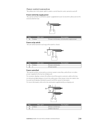
... turn on when power is closed. For more information, refer to the red wire after the fuse. For Simrad and B&G displays connect the yellow wire of the power connector cable to supply power Power on /off . A B A Key Wire color A Yellow B Description Power control wire Master slave bus Installation | Halo20, 20+ and 24 Dome Radars Installation Manual | 19 A Key Wire color A Yellow Description Power control wire, connected to the bus. For Lowrance...
... turn on when power is closed. For more information, refer to the red wire after the fuse. For Simrad and B&G displays connect the yellow wire of the power connector cable to supply power Power on /off . A B A Key Wire color A Yellow B Description Power control wire Master slave bus Installation | Halo20, 20+ and 24 Dome Radars Installation Manual | 19 A Key Wire color A Yellow Description Power control wire, connected to the bus. For Lowrance...
HALO 20 20 and 24 Installation Manual
Page 20
... unit to locate the settings to zero. Adjust bearing alignment Aligns the heading marker on the radar image. This ensures that could cause unwanted reflections or interference to appear on the screen with the EBL are ...Halo20+ and Halo24 Radars. Halo light ¼ Note: Only available for use . Determines the light level of the vessel. Increase the suppression if there are displayed accurately. Target loss in required. Make the following settings before turning the blue accent lights ON. 20 | Setup and configuration | Halo20, 20+ and 24 Dome Radars Installation Manual...
... unit to locate the settings to zero. Adjust bearing alignment Aligns the heading marker on the radar image. This ensures that could cause unwanted reflections or interference to appear on the screen with the EBL are ...Halo20+ and Halo24 Radars. Halo light ¼ Note: Only available for use . Determines the light level of the vessel. Increase the suppression if there are displayed accurately. Target loss in required. Make the following settings before turning the blue accent lights ON. 20 | Setup and configuration | Halo20, 20+ and 24 Dome Radars Installation Manual...
HALO 20 20 and 24 Installation Manual
Page 22
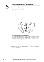
... MARPA or Velocity Track to operate. 22 | Replacing a Broadband 3G/4G Radar | Halo20, 20+ and 24 Dome Radars Installation Manual Refer to "Technical specifications" on page 19. For information contact Navico customer service. At mounting location: 4. Turn the locking collar to one side so the cable channel is left open. Connect the 4G cable wires to power as specified. Insert the connector of the...
... MARPA or Velocity Track to operate. 22 | Replacing a Broadband 3G/4G Radar | Halo20, 20+ and 24 Dome Radars Installation Manual Refer to "Technical specifications" on page 19. For information contact Navico customer service. At mounting location: 4. Turn the locking collar to one side so the cable channel is left open. Connect the 4G cable wires to power as specified. Insert the connector of the...
HALO 20 20 and 24 Installation Manual
Page 23
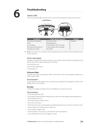
...on the Ethernet cable and replace it • Try another Ethernet port on the chart or when current display software is too old to support radar. Recommendations Ensure that the Ethernet light is up /Upgrading Fault Low ...problems persists check that the software is blinking at the radar and at the back of the scanner that indicates the status of the radar and display unit software: www.lowrance.com www.simrad-yachting.com www.bandg.com Unknown Radar Generally seen when overlaying the radar on the display or switch Troubleshooting | Halo20, 20+ and 24 Dome Radars Installation Manual...
...on the Ethernet cable and replace it • Try another Ethernet port on the chart or when current display software is too old to support radar. Recommendations Ensure that the Ethernet light is up /Upgrading Fault Low ...problems persists check that the software is blinking at the radar and at the back of the scanner that indicates the status of the radar and display unit software: www.lowrance.com www.simrad-yachting.com www.bandg.com Unknown Radar Generally seen when overlaying the radar on the display or switch Troubleshooting | Halo20, 20+ and 24 Dome Radars Installation Manual...

HALO 20 20 and 24 Installation Manual
Page 24
... settings including installation settings Scanner not detected 1. Check input Voltage 1. No scanner Happens when Ethernet connection is established between radar and display, but an internal error in the scanner prevents normal radar operation. Recommendations • Check supply voltage/current • If persistent, power cycle the system, check the scanner cable / RJ45 • Possible internal fault with the radar, contact service Error codes...
... settings including installation settings Scanner not detected 1. Check input Voltage 1. No scanner Happens when Ethernet connection is established between radar and display, but an internal error in the scanner prevents normal radar operation. Recommendations • Check supply voltage/current • If persistent, power cycle the system, check the scanner cable / RJ45 • Possible internal fault with the radar, contact service Error codes...

