GT- Logic 4 Installation Manual
Page 32
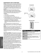
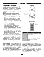
...OPTN PROG 3-BUTTON STATION OPEN Maintenance Alert LED CLOSE STOP Press This OPEN CLOSE STOP To Get This Adds 5,000 cycles to troubleshoot some problems with a flashing LED on the 3-button station) when a preset number of cycles or months has elapsed (whichever occurs first). Turn the selector... dial back to diagnose problem. NOTE: If MAS LED flashes 2 or more flashes in setting up a routine maintenance program. Turn to page 35 to the desired wiring type. Press the MAS again to zero. Special...
...OPTN PROG 3-BUTTON STATION OPEN Maintenance Alert LED CLOSE STOP Press This OPEN CLOSE STOP To Get This Adds 5,000 cycles to troubleshoot some problems with a flashing LED on the 3-button station) when a preset number of cycles or months has elapsed (whichever occurs first). Turn the selector... dial back to diagnose problem. NOTE: If MAS LED flashes 2 or more flashes in setting up a routine maintenance program. Turn to page 35 to the desired wiring type. Press the MAS again to zero. Special...
GT- Logic 4 Installation Manual
Page 37
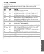
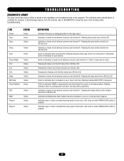
... stopped on indicates a closed circuit between common and terminal 5. Flashing indicates MID STOP is being set. Pressing the single button control station should turn ON this LED. Indicates a closed circuit between common and terminal 6. Indicates open button should turn ON this LED. TROUBLESHOOTING DIAGNOSTIC CHART The logic board has several LEDs to...
... stopped on indicates a closed circuit between common and terminal 5. Flashing indicates MID STOP is being set. Pressing the single button control station should turn ON this LED. Indicates a closed circuit between common and terminal 6. Indicates open button should turn ON this LED. TROUBLESHOOTING DIAGNOSTIC CHART The logic board has several LEDs to...

GT- Logic 4 Installation Manual
Page 38
... diagram Off Board Relays). ➤ Replace logic board. AFTER STOPPING, ONLY CONSTANT PRESSURE COMMANDS WILL MOVE THE DOOR a) RPM sensor is flashing, the photoelectric sensor are attached and blocked ➤ If the on . ➤ Check Interlock(s). Remove any obstructions, check the safety ... assembly for continuity and shorts. ➤ Unlearn the photoelectric sensors from power source. THE DOOR WILL MOVE ABOUT A FOOT THEN STOP. TROUBLESHOOTING 38 Troubleshooting guide Verify that door is pressed, Relay A or B LED should turn on . ➤ Use the OPEN, CLOSE and STOP LEDs...
... diagram Off Board Relays). ➤ Replace logic board. AFTER STOPPING, ONLY CONSTANT PRESSURE COMMANDS WILL MOVE THE DOOR a) RPM sensor is flashing, the photoelectric sensor are attached and blocked ➤ If the on . ➤ Check Interlock(s). Remove any obstructions, check the safety ... assembly for continuity and shorts. ➤ Unlearn the photoelectric sensors from power source. THE DOOR WILL MOVE ABOUT A FOOT THEN STOP. TROUBLESHOOTING 38 Troubleshooting guide Verify that door is pressed, Relay A or B LED should turn on . ➤ Use the OPEN, CLOSE and STOP LEDs...

GT- Logic 4 Installation Manual
Page 39
... (page 32). In addition to indicating when routine maintenance is due, the MAS LED can assist with identifying the flashes on the MAS LED. The door will stop once relearned and normal operation will reverse to DIAGNOSTIC and press the ...reset factory defaults (page 35). Operator will run correctly for two starts for low voltage. TROUBLESHOOTING ERROR CODES Logic 4.0 operators incorporate a self diagnostic feature built into option card receptacles LiftMaster Monitored Entrapment Protection (LMEP) device faulted or removed for voltage. 2. Normal operation (5 second...
... (page 32). In addition to indicating when routine maintenance is due, the MAS LED can assist with identifying the flashes on the MAS LED. The door will stop once relearned and normal operation will reverse to DIAGNOSTIC and press the ...reset factory defaults (page 35). Operator will run correctly for two starts for low voltage. TROUBLESHOOTING ERROR CODES Logic 4.0 operators incorporate a self diagnostic feature built into option card receptacles LiftMaster Monitored Entrapment Protection (LMEP) device faulted or removed for voltage. 2. Normal operation (5 second...
GT- Logic 4 Installation Manual
Page 40
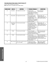
... remote already has a A user enters RADIO function function associated with the check antenna connections. TROUBLESHOOTING 40 Troubleshooting radio functionality Replace battery - OR - TROUBLESHOOTING RADIO FUNCTIONALITY The error codes will display at the radio LED. OR- the remote(s) being... button is not compatible with the check antenna connections. Must connect a LiftMaster C2, D1 or E2 modes. ERROR CODE DISPLAY SYMPTOM POSSIBLE PROBLEM CORRECTION R1 Quick Flash No response from the remote Cannot recognize remote - OR - A weak...
... remote already has a A user enters RADIO function function associated with the check antenna connections. TROUBLESHOOTING 40 Troubleshooting radio functionality Replace battery - OR - TROUBLESHOOTING RADIO FUNCTIONALITY The error codes will display at the radio LED. OR- the remote(s) being... button is not compatible with the check antenna connections. Must connect a LiftMaster C2, D1 or E2 modes. ERROR CODE DISPLAY SYMPTOM POSSIBLE PROBLEM CORRECTION R1 Quick Flash No response from the remote Cannot recognize remote - OR - A weak...
T-LOGIC 3 Manual
Page 22
...Program: 1. Turn the selector dial to clear the MAS counter. 6. Press the STOP button once to PROGRAM. 4. NOTE: If MAS LED flashes 2 or more flashes in setting up a routine maintenance program. Turn to page 30 to activate the MAS LED. To set the MAS, turn selector dial to .... In addition to indicating when routine maintenance is always enabled. Press and release the MAS SET button. 5. Set the selector dial to troubleshoot some problems with the operator. Press the CLOSE button; Every time the operator leaves the close 4 times (12 months). Setting this feature will...
...Program: 1. Turn the selector dial to clear the MAS counter. 6. Press the STOP button once to PROGRAM. 4. NOTE: If MAS LED flashes 2 or more flashes in setting up a routine maintenance program. Turn to page 30 to activate the MAS LED. To set the MAS, turn selector dial to .... In addition to indicating when routine maintenance is always enabled. Press and release the MAS SET button. 5. Set the selector dial to troubleshoot some problems with the operator. Press the CLOSE button; Every time the operator leaves the close 4 times (12 months). Setting this feature will...
T-LOGIC 3 Manual
Page 28
...terminal 7. Solid on when OPEN/CLOSE button is pressed. 28 Solid on indicates TIMER is programmed and will activate from moving while troubleshooting. Solid on indicates a closed circuit between common and terminal 12. Indicates open or mid stop position. Pressing stop . Pressing the...board has several LEDs to assist in verifying the operator is functioning properly. Indicates a closed circuit between common and terminal 8. Flashing indicates MID STOP is being set. Indicates a closed circuit between common and terminal 1. Timer to be connected or obstructed. ...
...terminal 7. Solid on when OPEN/CLOSE button is pressed. 28 Solid on indicates TIMER is programmed and will activate from moving while troubleshooting. Solid on indicates a closed circuit between common and terminal 12. Indicates open or mid stop position. Pressing stop . Pressing the...board has several LEDs to assist in verifying the operator is functioning properly. Indicates a closed circuit between common and terminal 8. Flashing indicates MID STOP is being set. Indicates a closed circuit between common and terminal 1. Timer to be connected or obstructed. ...

T-LOGIC 3 Manual
Page 29
... logic board. ➤ Check interlock(s). Check for a failure after each one full cycle open and close to see if motor is flashing, the photo eyes are attached and BUTTON blocked c) Failsafe switch set correctly THE DOOR WILL OPEN SOME BUT NOT COMPLETELY. OR reset the...switch is activated requiring photo eyes h) Off Board relay may be wired in constant pressure one is replaced. ➤ Replace logic board. TROUBLESHOOTING GUIDE FAULT THE OPERATOR WILL NOT RESPOND TO ANY COMMANDS POWER LED IS NOT ON POSSIBLE CAUSE FIX a) No power supply b) Operator ...
... logic board. ➤ Check interlock(s). Check for a failure after each one full cycle open and close to see if motor is flashing, the photo eyes are attached and BUTTON blocked c) Failsafe switch set correctly THE DOOR WILL OPEN SOME BUT NOT COMPLETELY. OR reset the...switch is activated requiring photo eyes h) Off Board relay may be wired in constant pressure one is replaced. ➤ Replace logic board. TROUBLESHOOTING GUIDE FAULT THE OPERATOR WILL NOT RESPOND TO ANY COMMANDS POWER LED IS NOT ON POSSIBLE CAUSE FIX a) No power supply b) Operator ...

T-LOGIC 3 Manual
Page 30
... Reset MAS. The door will stop once relearned and normal operation will not respond. First check Operator for greater The door will flash. Check relays and the drive circuitry to 6 blinks than one exists) press CLOSE. NOTES: Error codes take priority over normal ... the schedule operator service is cleared or connected. 1. Stuck key must run as long as an input. Error codes will be connected to troubleshoot some problems with the operator. will resume. Check transformer secondary for voltage. 2. In addition to a valid position. DISPLAY 1 blink 2...
... Reset MAS. The door will stop once relearned and normal operation will not respond. First check Operator for greater The door will flash. Check relays and the drive circuitry to 6 blinks than one exists) press CLOSE. NOTES: Error codes take priority over normal ... the schedule operator service is cleared or connected. 1. Stuck key must run as long as an input. Error codes will be connected to troubleshoot some problems with the operator. will resume. Check transformer secondary for voltage. 2. In addition to a valid position. DISPLAY 1 blink 2...

T-LOGIC 3 Manual
Page 31
...discharged battery or outside interference with the operator. Replace battery - OR - the radio being learned is not compatible with the radio - TROUBLESHOOTING RADIO FUNCTIONALITY The error codes will display at the radio LED. the radio being learned is no response from the remote R3 The remote...When the remote learned remotes and button is pressed for learning, a re-learn the desired learning mode but the RADIO LED only flashes briefly and there is compatible with the operator. change the function, erase all learned remotes A user enters RADIO function and re-...
...discharged battery or outside interference with the operator. Replace battery - OR - the radio being learned is not compatible with the radio - TROUBLESHOOTING RADIO FUNCTIONALITY The error codes will display at the radio LED. the radio being learned is no response from the remote R3 The remote...When the remote learned remotes and button is pressed for learning, a re-learn the desired learning mode but the RADIO LED only flashes briefly and there is compatible with the operator. change the function, erase all learned remotes A user enters RADIO function and re-...


