
GT- Logic 4 Installation Manual
Page 2
... Location 16 Mounting 17 Install the Manual Disconnect 17 WIRING 18-19 Power and Ground 18 Control Station 19 ENTRAPMENT PROTECTION 20-22 LiftMaster Monitored Entrapment Protection (LMEP 20 Install the Photoelectric Sensors (Provided 21 Mount the Photoelectric Sensors (Provided 22 Wire the.... . . 36 Brake (If Present 36 How to Programming 28 Determine and Set Wiring Type 29 Programming Remote Controls 30-31 Maintenance Alert System (MAS 32 Open Mid Stop 33 Timer-To-Close 33-34 Car Dealer Mode 34 Maximum Run Timer (MRT 35 Resetting Factory Defaults -
... Location 16 Mounting 17 Install the Manual Disconnect 17 WIRING 18-19 Power and Ground 18 Control Station 19 ENTRAPMENT PROTECTION 20-22 LiftMaster Monitored Entrapment Protection (LMEP 20 Install the Photoelectric Sensors (Provided 21 Mount the Photoelectric Sensors (Provided 22 Wire the.... . . 36 Brake (If Present 36 How to Programming 28 Determine and Set Wiring Type 29 Programming Remote Controls 30-31 Maintenance Alert System (MAS 32 Open Mid Stop 33 Timer-To-Close 33-34 Car Dealer Mode 34 Maximum Run Timer (MRT 35 Resetting Factory Defaults -

GT- Logic 4 Installation Manual
Page 4
...all GT models) Entrapment Protection Device: Model CPS-U photoelectric sensors (standard) NOTE: The tracks are shipped separately. ENTRAPMENT PROTECTION: LiftMaster Monitored Entrapment Protection (LMEP) Photoelectric Sensors (CPS-U Through beam used to the bottom edge of door. OPERATOR SPECIFICATIONS MOTOR TYPE ...Hardware box (includes fasteners, track spacers, trolley, door arm assembly, front idler and header mounting bracket) 3-Button control station with open and close with LED Trolley drive chain: #48 for 1/3 and 1/2 HP, #41 for sensing device to reverse and auxiliary devices...
...all GT models) Entrapment Protection Device: Model CPS-U photoelectric sensors (standard) NOTE: The tracks are shipped separately. ENTRAPMENT PROTECTION: LiftMaster Monitored Entrapment Protection (LMEP) Photoelectric Sensors (CPS-U Through beam used to the bottom edge of door. OPERATOR SPECIFICATIONS MOTOR TYPE ...Hardware box (includes fasteners, track spacers, trolley, door arm assembly, front idler and header mounting bracket) 3-Button control station with open and close with LED Trolley drive chain: #48 for 1/3 and 1/2 HP, #41 for sensing device to reverse and auxiliary devices...
GT- Logic 4 Installation Manual
Page 10
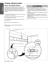
..., sticks, or is generally mounted over the center of the door. AVERTISSEMENT 5 Fasten the header bracket with a vertical line, extend the line onto the ceiling. 2 Open the door to interfering structures or location of travel. 3 Center the header bracket on header wall or ceiling, otherwise door might NOT reverse when required.
..., sticks, or is generally mounted over the center of the door. AVERTISSEMENT 5 Fasten the header bracket with a vertical line, extend the line onto the ceiling. 2 Open the door to interfering structures or location of travel. 3 Center the header bracket on header wall or ceiling, otherwise door might NOT reverse when required.
GT- Logic 4 Installation Manual
Page 12
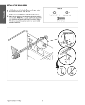
... arm to door manufacturer's instructions for recommended installation guidelines. HARDWARE A Flanged Hex Nut 3/8"-16 (2) B Nylok Nut 3/8"-16 (1) Bolt 3/8"-16 x 1" (3) NOTICE 1 A B 2 Typical installation - Make sure the open side of the notch on the door arm faces the door. 2 Position the door bracket to the center line of the door and attach the...
... arm to door manufacturer's instructions for recommended installation guidelines. HARDWARE A Flanged Hex Nut 3/8"-16 (2) B Nylok Nut 3/8"-16 (1) Bolt 3/8"-16 x 1" (3) NOTICE 1 A B 2 Typical installation - Make sure the open side of the notch on the door arm faces the door. 2 Position the door bracket to the center line of the door and attach the...

GT- Logic 4 Installation Manual
Page 13
...sensing device to reverse and auxiliary devices to open and close with open override. ELECTRICAL TRANSFORMER 24Vac Secondary CONTROL STATION NEMA 3-Button Station Open/Close/Stop w/LED WIRING TYPE C2 (Standard) Momentary contact to OPEN and STOP, constant pressure to provide non-contact... station with electrical interlock for manual door operation Model HJ Includes both floor level disconnect systems stated above ENTRAPMENT PROTECTION: LiftMaster Monitored Entrapment Protection (LMEP) Photoelectric Sensors (CPS-U Through beam used to CLOSE, plus wiring for optional wiring types and...
...sensing device to reverse and auxiliary devices to open and close with open override. ELECTRICAL TRANSFORMER 24Vac Secondary CONTROL STATION NEMA 3-Button Station Open/Close/Stop w/LED WIRING TYPE C2 (Standard) Momentary contact to OPEN and STOP, constant pressure to provide non-contact... station with electrical interlock for manual door operation Model HJ Includes both floor level disconnect systems stated above ENTRAPMENT PROTECTION: LiftMaster Monitored Entrapment Protection (LMEP) Photoelectric Sensors (CPS-U Through beam used to CLOSE, plus wiring for optional wiring types and...

GT- Logic 4 Installation Manual
Page 16
... the operator and the door shaft. The handing is out of balance. If your ATTENTION installation causes the hand chain to hang in the door opening, hook the chain to remain functional, install an interlock switch. • ALWAYS call a trained door systems technician if door binds, sticks or is indicated by...
... the operator and the door shaft. The handing is out of balance. If your ATTENTION installation causes the hand chain to hang in the door opening, hook the chain to remain functional, install an interlock switch. • ALWAYS call a trained door systems technician if door binds, sticks or is indicated by...
GT- Logic 4 Installation Manual
Page 18
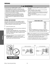
... conduit. To change motor rotation, exchange incoming power leads L1 and L2. 3 Attach power and ground wires to REV. 2. USE COPPER WIRE ONLY. Remove CLOSE/OPEN decal and reattach appropriately. 1 Single Phase Power Wiring 3 Three Phase Power Wiring Line Power Hot 2 115/230 Vac Single Phase Neutral Ground Line Power 208...
... conduit. To change motor rotation, exchange incoming power leads L1 and L2. 3 Attach power and ground wires to REV. 2. USE COPPER WIRE ONLY. Remove CLOSE/OPEN decal and reattach appropriately. 1 Single Phase Power Wiring 3 Three Phase Power Wiring Line Power Hot 2 115/230 Vac Single Phase Neutral Ground Line Power 208...
GT- Logic 4 Installation Manual
Page 19
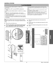
... that is NOT connected BEFORE installing door control. ENCIA CIÓN 3 5' 5 1 2 4 24VAC 14 24VAC DATA 13 TIMER ^OPEN DEFEAT 12 ^ CLOSE O COMMON 11 STOP 24VAC POWER 24VAC TIMER DEFEAT MAS 10 COMMON MAS LMEP 9 LMEP: TIMER NABLE EDGE...: OPEN EDGE 8 CLOSE OPEN ADVERTSTOP ENCIA 7 COMMON CLOSE 6 N STOP 5 ADVERTENCIA SBC COMMON 4 UL Entrapment Placard WARNING 3 2 SBC 1 3-Button Station OPEN CLOSE STOP Maintenance Alert LED (RD) (WH) Open Close Stop Moving Door Can Cause Serious Injury or Death...
... that is NOT connected BEFORE installing door control. ENCIA CIÓN 3 5' 5 1 2 4 24VAC 14 24VAC DATA 13 TIMER ^OPEN DEFEAT 12 ^ CLOSE O COMMON 11 STOP 24VAC POWER 24VAC TIMER DEFEAT MAS 10 COMMON MAS LMEP 9 LMEP: TIMER NABLE EDGE...: OPEN EDGE 8 CLOSE OPEN ADVERTSTOP ENCIA 7 COMMON CLOSE 6 N STOP 5 ADVERTENCIA SBC COMMON 4 UL Entrapment Placard WARNING 3 2 SBC 1 3-Button Station OPEN CLOSE STOP Maintenance Alert LED (RD) (WH) Open Close Stop Moving Door Can Cause Serious Injury or Death...
GT- Logic 4 Installation Manual
Page 20
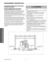
... of Garage- When properly connected and aligned, the photoelectric sensors will detect an obstruction in the fully opened or closed position BEFORE installing the LiftMaster Monitored Entrapment Protection device. WARNING To prevent possible SERIOUS INJURY or DEATH from the control station. If ... ENTRAPMENT PROTECTION DEVICES A LiftMaster Monitored Entrapment Protection (LMEP) device is not installed, constant pressure to close will be required from a closing , the door will stop and typically reverse to the full open position. The LEDs on both the leading and trailing edge. &#...
... of Garage- When properly connected and aligned, the photoelectric sensors will detect an obstruction in the fully opened or closed position BEFORE installing the LiftMaster Monitored Entrapment Protection device. WARNING To prevent possible SERIOUS INJURY or DEATH from the control station. If ... ENTRAPMENT PROTECTION DEVICES A LiftMaster Monitored Entrapment Protection (LMEP) device is not installed, constant pressure to close will be required from a closing , the door will stop and typically reverse to the full open position. The LEDs on both the leading and trailing edge. &#...
GT- Logic 4 Installation Manual
Page 22
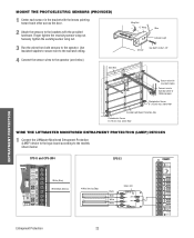
... and CPS-UN4 CPS-EI POWER 24VAC TIMER DEFEAT COMMON MAS LMEP EDGE OPEN CLOSE STOP COMMON SBC 24VAC POWER 24VAC TIMER DEFEAT COMMON MAS 3-PHASE 1-PHASE LMEP: TTC TIMER ENABLE EDGE: OPEN 3 CLOSE TS FSTS DIAG STOP COMMON White (Blue) White/Black (Brown)... Sensor Hex Bolt 1/4-20x1-1/2" ENTRAPMENT PROTECTION Secure wire with the provided hardware. above floor WIRE THE LIFTMASTER MONITORED ENTRAPMENT PROTECTION (LMEP) DEVICES 1 Connect the LiftMaster Monitored Entrapment Protection (LMEP) device to the logic board according to the models shown below ). Securely tighten...
... and CPS-UN4 CPS-EI POWER 24VAC TIMER DEFEAT COMMON MAS LMEP EDGE OPEN CLOSE STOP COMMON SBC 24VAC POWER 24VAC TIMER DEFEAT COMMON MAS 3-PHASE 1-PHASE LMEP: TTC TIMER ENABLE EDGE: OPEN 3 CLOSE TS FSTS DIAG STOP COMMON White (Blue) White/Black (Brown)... Sensor Hex Bolt 1/4-20x1-1/2" ENTRAPMENT PROTECTION Secure wire with the provided hardware. above floor WIRE THE LIFTMASTER MONITORED ENTRAPMENT PROTECTION (LMEP) DEVICES 1 Connect the LiftMaster Monitored Entrapment Protection (LMEP) device to the logic board according to the models shown below ). Securely tighten...
GT- Logic 4 Installation Manual
Page 23
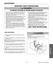
... is on . 5 When the retaining plate is released, verify that the retaining plate is clear of the limit nuts. 4AVERTISSEMENT Open the door to adjust the operator properly may cause SEVERE INJURY and DEATH. 10. Limits Adjustment WARNING ADJUSTMENT IMPORTANT SAFETY INSTRUCTIONS WARNING ... closed . Entrapment Protection device MUST be tested. NO ONE SHOULD CROSS THE PATH OF THE MOVING DOOR. 5. Failure to the fully open door falling rapidly and/or unexpectedly causing SEVERE INJURY or DEATH. 7. WARNING WARNING LIMIT ADJUSTMENT CAUTION 1 Begin with door control push buttons...
... is on . 5 When the retaining plate is released, verify that the retaining plate is clear of the limit nuts. 4AVERTISSEMENT Open the door to adjust the operator properly may cause SEVERE INJURY and DEATH. 10. Limits Adjustment WARNING ADJUSTMENT IMPORTANT SAFETY INSTRUCTIONS WARNING ... closed . Entrapment Protection device MUST be tested. NO ONE SHOULD CROSS THE PATH OF THE MOVING DOOR. 5. Failure to the fully open door falling rapidly and/or unexpectedly causing SEVERE INJURY or DEATH. 7. WARNING WARNING LIMIT ADJUSTMENT CAUTION 1 Begin with door control push buttons...
GT- Logic 4 Installation Manual
Page 24
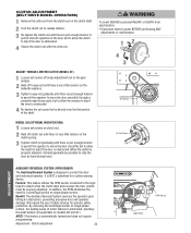
...the leading cause of motor failures is eliminated. (Auxiliary Reversal System not applicable on single phase motors. Clutch adjustment 24 LOSE OPEN RPM Sensor Logic Board WARNING WARNING C(BLEULTCTCADHRUAIVDTEJIUOMSONTDMEELNOTPERATORS) 1 Remove the cotter pin from electrocution: • Disconnect electric power BEFORE ... clutch nut gradually until there is just enough tension to permit the operator to move the door smoothly through a complete open/close cycle, but to allow the clutch to stop the door by hand during travel. (3) Set Screws ADVERTENCIA ADVERTENCIA ADJUSTMENT...
...the leading cause of motor failures is eliminated. (Auxiliary Reversal System not applicable on single phase motors. Clutch adjustment 24 LOSE OPEN RPM Sensor Logic Board WARNING WARNING C(BLEULTCTCADHRUAIVDTEJIUOMSONTDMEELNOTPERATORS) 1 Remove the cotter pin from electrocution: • Disconnect electric power BEFORE ... clutch nut gradually until there is just enough tension to permit the operator to move the door smoothly through a complete open/close cycle, but to allow the clutch to stop the door by hand during travel. (3) Set Screws ADVERTENCIA ADVERTENCIA ADJUSTMENT...
GT- Logic 4 Installation Manual
Page 25
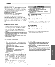
...modes. 5. If the green indicator lights are correct. 2. Adjust sensor vertically and/or horizontally until the MAS LED flashes. Press OPEN button. (The door should move in this code. TESTING TEST THE PHOTOELECTRIC SENSORS 1. The LMEP LED will not provide AVERTISSEMENT this... invisible light beam path is not obstructed), alignment is completed (approximately 2-3 seconds) only the appropriate LED's will reverse to fully open position in C2 or D1 mode. If the selector dial is released. ALIAGNTTHTEEPHNOTTOEILOECTNRIC SENSORS 1. WARNING To avoid SERIOUS personal INJURY or DEATH...
...modes. 5. If the green indicator lights are correct. 2. Adjust sensor vertically and/or horizontally until the MAS LED flashes. Press OPEN button. (The door should move in this code. TESTING TEST THE PHOTOELECTRIC SENSORS 1. The LMEP LED will not provide AVERTISSEMENT this... invisible light beam path is not obstructed), alignment is completed (approximately 2-3 seconds) only the appropriate LED's will reverse to fully open position in C2 or D1 mode. If the selector dial is released. ALIAGNTTHTEEPHNOTTOEILOECTNRIC SENSORS 1. WARNING To avoid SERIOUS personal INJURY or DEATH...
GT- Logic 4 Installation Manual
Page 26
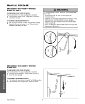
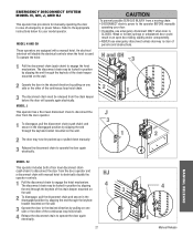
MANUAL RELEASE EMERGENCY DISCONNECT SYSTEM MODEL GT AND T TO DISCONNECT DOOR FROM OPERATOR The door should be in an open . Release handle. TO RECONNECT DOOR ARM TO TROLLEY 2 Lift free end of persons and obstructions. 1 AVERTISSEMENT ATTENTION 2 NOTICE...unless doorway is CLOSED. Weak or broken springs or unbalanced door could result in the fully closed position if possible. 1 Pull down . Emergency disconnect will open door falling rapidly and/or unexpectedly. • NEVER use emergency release handle to engage roll pin. Manual Release 26 ADVERTENCIA PRECAUCIÓN 1 N O ...
MANUAL RELEASE EMERGENCY DISCONNECT SYSTEM MODEL GT AND T TO DISCONNECT DOOR FROM OPERATOR The door should be in an open . Release handle. TO RECONNECT DOOR ARM TO TROLLEY 2 Lift free end of persons and obstructions. 1 AVERTISSEMENT ATTENTION 2 NOTICE...unless doorway is CLOSED. Weak or broken springs or unbalanced door could result in the fully closed position if possible. 1 Pull down . Emergency disconnect will open door falling rapidly and/or unexpectedly. • NEVER use emergency release handle to engage roll pin. Manual Release 26 ADVERTENCIA PRECAUCIÓN 1 N O ...
GT- Logic 4 Installation Manual
Page 27
... door again electrically. To operate the hoist: 1 Pull the disconnect chain (sash chain) to the appropriate instructions below for manually operating the door in an open door falling rapidly and/or unexpectedly. • NEVER use emergency disconnect ONLY when door is CLOSED. Weak or broken springs or unbalanced door could result...
... door again electrically. To operate the hoist: 1 Pull the disconnect chain (sash chain) to the appropriate instructions below for manually operating the door in an open door falling rapidly and/or unexpectedly. • NEVER use emergency disconnect ONLY when door is CLOSED. Weak or broken springs or unbalanced door could result...
GT- Logic 4 Installation Manual
Page 28
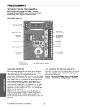
...wiring type) Main Motor Control Harness Connection LOGIC BOARD LED OVERVIEW NOTE: Before programming the logic board, set the operator's open and close limits. After the code has been provided the MAS LED will light up. PROGRAMMING Programming-Introduction to the Entrapment ... and Stop buttons are Open Limit Switch (OLS), Close Limit Switch (CLS) and Sensing Limit Switch (SLS). Once the power up process is activated). PROGRAMMING INTRODUCTION TO PROGRAMMING Many programmable functions require that a LiftMaster Entrapment Protection (LMEP) device be installed in the DIAG, ...
...wiring type) Main Motor Control Harness Connection LOGIC BOARD LED OVERVIEW NOTE: Before programming the logic board, set the operator's open and close limits. After the code has been provided the MAS LED will light up. PROGRAMMING Programming-Introduction to the Entrapment ... and Stop buttons are Open Limit Switch (OLS), Close Limit Switch (CLS) and Sensing Limit Switch (SLS). Once the power up process is activated). PROGRAMMING INTRODUCTION TO PROGRAMMING Many programmable functions require that a LiftMaster Entrapment Protection (LMEP) device be installed in the DIAG, ...
GT- Logic 4 Installation Manual
Page 29
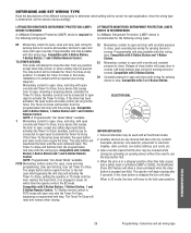
... ENTRAPMENT PROTECTION (LMEP) DEVICE IS REQUIRED A LiftMaster Entrapment Protection (LMEP) device is activated (LMEP or EDGE), the Restricted Close (RC) feature will be reversed while closing by activating an opening device without the need to stop with this wiring type. Programmable mid stop available with this wiring type. Compatible with 3-Button Station...
... ENTRAPMENT PROTECTION (LMEP) DEVICE IS REQUIRED A LiftMaster Entrapment Protection (LMEP) device is activated (LMEP or EDGE), the Restricted Close (RC) feature will be reversed while closing by activating an opening device without the need to stop with this wiring type. Programmable mid stop available with this wiring type. Compatible with 3-Button Station...
GT- Logic 4 Installation Manual
Page 30
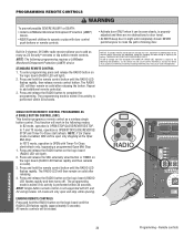
... possible SEVERE INJURY or DEATH: CAUTION • Install a LiftMaster Monitored Entrapment Protection (LMEP) • Activate door ONLY when it can be open and stop while opening. NOTE: The following programming requires a LiftMaster Monitored Entrapment Protection (LMEP) device. All remote controls will only open only stopping at the Open Mid-Stop. PRECAUCIÓN 3. Repeat to the following...
... possible SEVERE INJURY or DEATH: CAUTION • Install a LiftMaster Monitored Entrapment Protection (LMEP) • Activate door ONLY when it can be open and stop while opening. NOTE: The following programming requires a LiftMaster Monitored Entrapment Protection (LMEP) device. All remote controls will only open only stopping at the Open Mid-Stop. PRECAUCIÓN 3. Repeat to the following...
GT- Logic 4 Installation Manual
Page 31
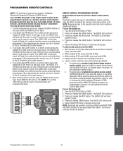
...use 1 channel of the 23 channels on the radio receiver.) 5. Learn a remote control by one of the following programming requires a LiftMaster Monitored Entrapment Protection (LMEP) device. The RADIO LED will light). 2. Press and release the MRT button. NOTE: Restoring the operator to...holding STOP and CLOSE, press and hold CLOSE. 3. Press and release the MID button. b. Programming a 3-button/three function remote control (OPEN/CLOSE/STOP), first push the button on the logic board will flash quickly 3 times. 4. Repeat steps 1 through 4 to add additional ...
...use 1 channel of the 23 channels on the radio receiver.) 5. Learn a remote control by one of the following programming requires a LiftMaster Monitored Entrapment Protection (LMEP) device. The RADIO LED will light). 2. Press and release the MRT button. NOTE: Restoring the operator to...holding STOP and CLOSE, press and hold CLOSE. 3. Press and release the MID button. b. Programming a 3-button/three function remote control (OPEN/CLOSE/STOP), first push the button on the logic board will flash quickly 3 times. 4. Repeat steps 1 through 4 to add additional ...
GT- Logic 4 Installation Manual
Page 32
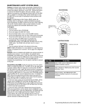
...how many cycles have elapsed since the last time the MAS was programmed, set the selector dial to Maintenance Alert System Activation Counter. The OPEN button LED will flash once for every 5,000 cycle increment programmed and the CLOSE button LED will flash once for every 5,000 cycles that... has elapsed. the OPEN LED will flash once for every 3 month increment programmed. the CLOSE LED will flash once for every 5,000 cycles increments. Once programmed, the ...
...how many cycles have elapsed since the last time the MAS was programmed, set the selector dial to Maintenance Alert System Activation Counter. The OPEN button LED will flash once for every 5,000 cycle increment programmed and the CLOSE button LED will flash once for every 5,000 cycles that... has elapsed. the OPEN LED will flash once for every 3 month increment programmed. the CLOSE LED will flash once for every 5,000 cycles increments. Once programmed, the ...


