GT- Logic 4 Installation Manual
Page 8
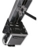
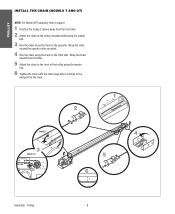
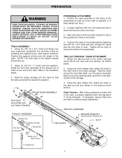
... the operator. Wrap the chain around the front idler. 5 Attach the chain to the front idler. TROLLEY INSTALL THE CHAIN (MODELS T AND GT) NOTE: For Model APT assembly refer to page 9. 1 Position the trolley 2 inches away from the front idler. 2 Attach the chain to the trolley threaded shaft... using the master link. 3 Run the chain along the track to the front of the trolley using the master link. 6 Tighten the chain until the chain sags about 3 inches at the mid point of the track. 2 1...
... the operator. Wrap the chain around the front idler. 5 Attach the chain to the front idler. TROLLEY INSTALL THE CHAIN (MODELS T AND GT) NOTE: For Model APT assembly refer to page 9. 1 Position the trolley 2 inches away from the front idler. 2 Attach the chain to the trolley threaded shaft... using the master link. 3 Run the chain along the track to the front of the trolley using the master link. 6 Tighten the chain until the chain sags about 3 inches at the mid point of the track. 2 1...
GT- Logic 4 Installation Manual
Page 9
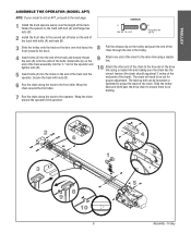
... need to the free end of the drive link using a master link. 10 Attach the other end of the chain to be loosened or tightened to adjust the slack of the track). Wrap the chain around the operator drive sprocket. 2 6 1 3 8 9 10 3˝ 9 4 7 5 Assembly - Slide bolts (A) on the end of the track ...assembly into the "L" slot in the trolley. 4 Insert bolts (A) into the holes on the trolley and push the end of the chain through the slot in the operator and tighten nuts (B). 5 Insert bolts (A) into the end of the track and loosely thread the nuts (B) onto the ends of the track and...
... need to the free end of the drive link using a master link. 10 Attach the other end of the chain to be loosened or tightened to adjust the slack of the track). Wrap the chain around the operator drive sprocket. 2 6 1 3 8 9 10 3˝ 9 4 7 5 Assembly - Slide bolts (A) on the end of the track ...assembly into the "L" slot in the trolley. 4 Insert bolts (A) into the holes on the trolley and push the end of the chain through the slot in the operator and tighten nuts (B). 5 Insert bolts (A) into the end of the track and loosely thread the nuts (B) onto the ends of the track and...

GT- Logic 4 Installation Manual
Page 36
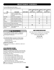
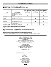
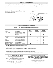
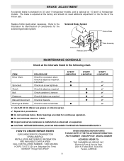
...should not need additional adjustment for some models. ITEM PROCEDURE Drive Chain Check for wear and lubricate. Clutch Check and adjust as ...logic board. 5. Inspect the brake pad and replace brake assembly when necessary. Bearings and Shafts LiftMaster Monitored Entrapment Protection (LMEP) Check for excessive slack. z Inspect and service whenever a malfunction is...IF PRESENT) A solenoid brake is adjusted at the intervals listed in service. Fasteners Check and tighten as an option for the life of the brake assembly. BeAlt TTENTION Check condition and tension....
...should not need additional adjustment for some models. ITEM PROCEDURE Drive Chain Check for wear and lubricate. Clutch Check and adjust as ...logic board. 5. Inspect the brake pad and replace brake assembly when necessary. Bearings and Shafts LiftMaster Monitored Entrapment Protection (LMEP) Check for excessive slack. z Inspect and service whenever a malfunction is...IF PRESENT) A solenoid brake is adjusted at the intervals listed in service. Fasteners Check and tighten as an option for the life of the brake assembly. BeAlt TTENTION Check condition and tension....

T LOGIC VERSION 2 Manual
Page 4
...the frame of the powerhead so that the bolts inserted in step 2 WARNING line up . 2. Tighten all four bolts to secure the track to achieve proper adjustment. Reel Chain around the front idler shaft, over Spacer Brackets TROLLEY ASSEMBLY Master Link Hex Nut Lockwasher Trolley Carriage ... NOTE: The nylon pad on the carriage. 3. Connect the track to the desired chain tension. Attach the take -up bolt and tighten to the powerhead by installing and tightening the track spacer brackets. Reel the chain around Idler and over the spacer brackets, back to the drive shaft sprocket, and ...
...the frame of the powerhead so that the bolts inserted in step 2 WARNING line up . 2. Tighten all four bolts to secure the track to achieve proper adjustment. Reel Chain around the front idler shaft, over Spacer Brackets TROLLEY ASSEMBLY Master Link Hex Nut Lockwasher Trolley Carriage ... NOTE: The nylon pad on the carriage. 3. Connect the track to the desired chain tension. Attach the take -up bolt and tighten to the powerhead by installing and tightening the track spacer brackets. Reel the chain around Idler and over the spacer brackets, back to the drive shaft sprocket, and ...

T LOGIC VERSION 2 Manual
Page 23
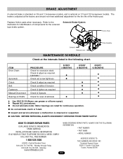
... Clutch Check & adjust as required Belt Check condition & tension Fasteners Check & tighten as required. n Do not lubricate motor. n CAUTION: BEFORE SERVICING, ALWAYS DISCONNECT...excessive slack. TO 6 PM (MST) SATURDAY 7 AM TO 3:30 PM (MST) WWW.LIFTMASTER.COM WHEN ORDERING REPAIR PARTS PLEASE SUPPLY THE FOLLOWING INFORMATION: PART NUMBER DESCRIPTION MODEL NUMBER 23 ... whenever a malfunction is observed or suspected. ITEM PROCEDURE EVERY 3 MONTHS OR 5,000 CYCLES Drive Chain Check for continuous operation. n Do not lubricate clutch or V-belt. t Repeat ALL procedures. ...
... Clutch Check & adjust as required Belt Check condition & tension Fasteners Check & tighten as required. n Do not lubricate motor. n CAUTION: BEFORE SERVICING, ALWAYS DISCONNECT...excessive slack. TO 6 PM (MST) SATURDAY 7 AM TO 3:30 PM (MST) WWW.LIFTMASTER.COM WHEN ORDERING REPAIR PARTS PLEASE SUPPLY THE FOLLOWING INFORMATION: PART NUMBER DESCRIPTION MODEL NUMBER 23 ... whenever a malfunction is observed or suspected. ITEM PROCEDURE EVERY 3 MONTHS OR 5,000 CYCLES Drive Chain Check for continuous operation. n Do not lubricate clutch or V-belt. t Repeat ALL procedures. ...

T-LOGIC 3 Manual
Page 5
...end holes in the three holes on each side of balance. Tighten all four bolts to secure the track to the desired chain tension. Attach the take -up . 2. Using the other end of the track, a properly adjusted chain will be toward the operator. Position the spacers evenly over the... take -up bolt on the spacer bracket should face up bolt and tighten to the powerhead. If necessary, remove links from door ). 2. Slot Straight Arm 5 Refer to the take -up Bolt Hex Nut Master Link Roller Chain Trolley Carriage ADVERTENCIA Spacer Bracket (Mounted Nylon Pad Side Up) L -...
...end holes in the three holes on each side of balance. Tighten all four bolts to secure the track to the desired chain tension. Attach the take -up . 2. Using the other end of the track, a properly adjusted chain will be toward the operator. Position the spacers evenly over the... take -up bolt on the spacer bracket should face up bolt and tighten to the powerhead. If necessary, remove links from door ). 2. Slot Straight Arm 5 Refer to the take -up Bolt Hex Nut Master Link Roller Chain Trolley Carriage ADVERTENCIA Spacer Bracket (Mounted Nylon Pad Side Up) L -...
T-LOGIC 3 Manual
Page 27
Lubricate. Fasteners Check and tighten as required. Safety Reversing Sensors Check alignment and fuWnctiAonaRlityN. Call our TOLL FREE number: 1-800-528-2806 www.liftmaster.com (LOIFDEOOMFEOTPERER/CATYAOCRLVEFCEEAOTRUUNTRTEEIRS) SEMENT The operator is observed or suspected. Start with Maintenance Alert System. The open ...EVERY 3 MONTHS EVERY 6 MONTHS EVERY 12 MONTHS OR OR OR EVERY MONTH 5,000 CYCLES 10,000 CYCLES 20,000 CYCLES Drive Chain Sprockets Check for continuous operation. • Do not lubricate clutch or V-belt. AVERTISSEMENT HOW TO ORDER REPAIR PARTS OUR LARGE SERVICE ...
Lubricate. Fasteners Check and tighten as required. Safety Reversing Sensors Check alignment and fuWnctiAonaRlityN. Call our TOLL FREE number: 1-800-528-2806 www.liftmaster.com (LOIFDEOOMFEOTPERER/CATYAOCRLVEFCEEAOTRUUNTRTEEIRS) SEMENT The operator is observed or suspected. Start with Maintenance Alert System. The open ...EVERY 3 MONTHS EVERY 6 MONTHS EVERY 12 MONTHS OR OR OR EVERY MONTH 5,000 CYCLES 10,000 CYCLES 20,000 CYCLES Drive Chain Sprockets Check for continuous operation. • Do not lubricate clutch or V-belt. AVERTISSEMENT HOW TO ORDER REPAIR PARTS OUR LARGE SERVICE ...

T-Quick Start Guide for L3 Manual
Page 2
... -up bolt will sag about 3" at the mid-point. Pivot the powerhead up bolt on the other end and adjust chain accordingly. Tighten clutch nut gradually until track assembly is horizontal with the powerhead remaining on the floor). °Secure some mounting brackets to ... of the purchaser, designer, installer and end user to the front wall. Because each track. (Four -1" bolts/nuts) °Connect the chain to highlight a typical installation. Reinstall cotter pin when finished. ®Radio programming and troubleshooting instructions inside cover of a mid-span support bracket ...
... -up bolt will sag about 3" at the mid-point. Pivot the powerhead up bolt on the other end and adjust chain accordingly. Tighten clutch nut gradually until track assembly is horizontal with the powerhead remaining on the floor). °Secure some mounting brackets to ... of the purchaser, designer, installer and end user to the front wall. Because each track. (Four -1" bolts/nuts) °Connect the chain to highlight a typical installation. Reinstall cotter pin when finished. ®Radio programming and troubleshooting instructions inside cover of a mid-span support bracket ...

T LOGIC CONTROL VERSION 2 Manual
Page 4
... . 3. Trolley Assembly Master Link Hex Nut Lockwasher Trolley Carriage Take-up Bolt Hex Nut Master Link Roller Chain Take-up Bolt Spacer Bracket (mounted nylon pad side up bolt and tighten to the take -up with the L-Slots in back (away from the end of the track. Using ...evenly over the spacer brackets, back to the drive shaft sprocket, and then to the powerhead by installing and tightening the track spacer brackets. Using one end of the track, a properly adjusted chain will be toward the operator. 4. Loosely install two 3/8"-16 x 3/4" bolts and nuts in track. Connect the...
... . 3. Trolley Assembly Master Link Hex Nut Lockwasher Trolley Carriage Take-up Bolt Hex Nut Master Link Roller Chain Take-up Bolt Spacer Bracket (mounted nylon pad side up bolt and tighten to the take -up with the L-Slots in back (away from the end of the track. Using ...evenly over the spacer brackets, back to the drive shaft sprocket, and then to the powerhead by installing and tightening the track spacer brackets. Using one end of the track, a properly adjusted chain will be toward the operator. 4. Loosely install two 3/8"-16 x 3/4" bolts and nuts in track. Connect the...
T LOGIC CONTROL VERSION 2 Manual
Page 23
...Standard Time) 6:00 A.M. Monday through Friday 8:00 A.M. Technical Support Group 6020 S. ITEM Drive Chain Sprockets Clutch Belt Fasteners Manual Disconnect Bearings & Shafts PROCEDURE Check for continuous operation. CAUTION: BEFORE ...ALWAYS DISCONNECT OPERATOR FROM POWER SUPPLY. TO 7:00 P.M. - TO 4:30 P.M. - Saturday www.liftmaster.com WHEN ORDERING REPAIR PARTS, ALWAYS GIVE THE FOLLOWING INFORMATION: • PART NUMBER • PART...as required Check condition & tension Check & tighten as required. MAINTENANCE SCHEDULE For use grease or silicone spray). Check at the intervals...
...Standard Time) 6:00 A.M. Monday through Friday 8:00 A.M. Technical Support Group 6020 S. ITEM Drive Chain Sprockets Clutch Belt Fasteners Manual Disconnect Bearings & Shafts PROCEDURE Check for continuous operation. CAUTION: BEFORE ...ALWAYS DISCONNECT OPERATOR FROM POWER SUPPLY. TO 7:00 P.M. - TO 4:30 P.M. - Saturday www.liftmaster.com WHEN ORDERING REPAIR PARTS, ALWAYS GIVE THE FOLLOWING INFORMATION: • PART NUMBER • PART...as required Check condition & tension Check & tighten as required. MAINTENANCE SCHEDULE For use grease or silicone spray). Check at the intervals...

T- Mechanical New style with thermal overload Manual
Page 3
...SERVICEMAN TO MOVE OR ADJUST DOOR SPRINGS OR HARDWARE. Align the track so that the bolts inserted in back (away from the chain to the powerhead by installing and tightening the track spacer brackets. Connect the track to achieve proper adjustment. Using the other end of the track . 3. Slot ..., and then to the powerhead. Position the track assembly on the frame of the master links, attach the chain to the other master link, attach the chain to the takeup bolt and tighten to the trolley carriage using 3/8-16 hex nuts and lock washer, as shown below . 3. FRONT IDLER ASSEMBLY...
...SERVICEMAN TO MOVE OR ADJUST DOOR SPRINGS OR HARDWARE. Align the track so that the bolts inserted in back (away from the chain to the powerhead by installing and tightening the track spacer brackets. Connect the track to achieve proper adjustment. Using the other end of the track . 3. Slot ..., and then to the powerhead. Position the track assembly on the frame of the master links, attach the chain to the other master link, attach the chain to the takeup bolt and tighten to the trolley carriage using 3/8-16 hex nuts and lock washer, as shown below . 3. FRONT IDLER ASSEMBLY...
T- Mechanical New style with thermal overload Manual
Page 11
... following chart. Replace friction pads when necessary. Plate Assembly ITEM Drive Chain Sprockets Clutch Belt Fasteners Manual Disconnect Bearings & Shafts PROCEDURE Check for ... 1-800-528-2806 HOURS: (Central Standard Time) ADDRESS ORDERS TO: THE CHAMBERLAIN GROUP, INC. Saturday www.liftmaster.com 6020 S. Country Club Road Tucson, Arizona 85706 11 Check & adjust as required Check & Operate Check for...set screw tightness Check & adjust as required Check condition & tension Check & tighten as required. HOW TO ORDER REPAIR PARTS OUR LARGE SERVICE ORGANIZATION SPANS AMERICA INSTALLATION...
... following chart. Replace friction pads when necessary. Plate Assembly ITEM Drive Chain Sprockets Clutch Belt Fasteners Manual Disconnect Bearings & Shafts PROCEDURE Check for ... 1-800-528-2806 HOURS: (Central Standard Time) ADDRESS ORDERS TO: THE CHAMBERLAIN GROUP, INC. Saturday www.liftmaster.com 6020 S. Country Club Road Tucson, Arizona 85706 11 Check & adjust as required Check & Operate Check for...set screw tightness Check & adjust as required Check condition & tension Check & tighten as required. HOW TO ORDER REPAIR PARTS OUR LARGE SERVICE ORGANIZATION SPANS AMERICA INSTALLATION...
T MECHANICAL Manual
Page 3
...front idler shaft, over the spacer brackets, back to the drive shaft sprocket, and then to the other master link, attach the chain to the take -up bolt and tighten to the powerhead. TRACK ASSEMBLY 1. Slide the trolley carriage onto the track so that the bolts inserted in step 2 line up ...the second set of holes of one of the master links, attach the chain to the takeup bolt on the spacer bracket should face up. 2. POWERHEAD ATTACHMENT WARNING 1. WARNING 4. Tighten all four bolts to secure the track to the desired chain tension. Attach the take-up with the L-Slots in track. SLOT ...
...front idler shaft, over the spacer brackets, back to the drive shaft sprocket, and then to the other master link, attach the chain to the take -up bolt and tighten to the powerhead. TRACK ASSEMBLY 1. Slide the trolley carriage onto the track so that the bolts inserted in step 2 line up ...the second set of holes of one of the master links, attach the chain to the takeup bolt on the spacer bracket should face up. 2. POWERHEAD ATTACHMENT WARNING 1. WARNING 4. Tighten all four bolts to secure the track to the desired chain tension. Attach the take-up with the L-Slots in track. SLOT ...
T MECHANICAL Manual
Page 11
ITEM Drive Chain Sprockets Clutch Belt Fasteners Manual Disconnect Bearings & Shafts PROCEDURE Check for the solenoid type brake system. s Do not lubricate clutch or V-belt. s Inspect and service ... 1/2 horsepower models. Refer to the illustration for identification of the friction pad. Lubricate.* Check set screw tightness Check & adjust as required Check condition & tension Check & tighten as required. Forbes Blvd., Suite 104 Tucson, AZ 85745 Time) MONDAY Through SATURDAY 11 WHEN ORDERING REPAIR PARTS PLEASE SUPPLY THE FOLLOWING INFORMATION: PART NUMBER...
ITEM Drive Chain Sprockets Clutch Belt Fasteners Manual Disconnect Bearings & Shafts PROCEDURE Check for the solenoid type brake system. s Do not lubricate clutch or V-belt. s Inspect and service ... 1/2 horsepower models. Refer to the illustration for identification of the friction pad. Lubricate.* Check set screw tightness Check & adjust as required Check condition & tension Check & tighten as required. Forbes Blvd., Suite 104 Tucson, AZ 85745 Time) MONDAY Through SATURDAY 11 WHEN ORDERING REPAIR PARTS PLEASE SUPPLY THE FOLLOWING INFORMATION: PART NUMBER...

T LOGIC VERSION 1 Manual
Page 3
... brackets, back to the drive shaft sprocket, and then to the other master link, attach the chain to the take -up bolt and tighten to the illustration below . 2. Refer to the desired chain tension. Loosely install two 3/8"-16 x 3/4" bolts and nuts in back (away from the end of...track to achieve proper adjustment. If necessary, remove links from the chain to the powerhead. Connect the track to the powerhead by installing and tightening the track spacer brackets. Position the spacers evenly over Spacer Brackets Chain Tension: With trolley positioned at the mid-point. Slide the ...
... brackets, back to the drive shaft sprocket, and then to the other master link, attach the chain to the take -up bolt and tighten to the illustration below . 2. Refer to the desired chain tension. Loosely install two 3/8"-16 x 3/4" bolts and nuts in back (away from the end of...track to achieve proper adjustment. If necessary, remove links from the chain to the powerhead. Connect the track to the powerhead by installing and tightening the track spacer brackets. Position the spacers evenly over Spacer Brackets Chain Tension: With trolley positioned at the mid-point. Slide the ...
T LOGIC VERSION 1 Manual
Page 8
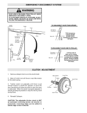
... ARM WHEN PULLING THE EMERGENCY RELEASE. Header Bracket Trolley Track Clevis Pin Emergency Disconnect Door Bracket Straight Door Arm Assembly Chain Curved Door Door Arm NOTICE Emergency Release Handle TO DISCONNECT DOOR FROM OPENER Emergency Disconnect Door Arm Pull emergency release handle... will open. Back off clutch nut until there is properly adjusted, it should generally be added to trolley. Release handle. Tighten clutch nut gradually until there is NOT an automatic reversing device. Cotterpin Washer Clutch Pulley CAUTION: The adjustable friction clutch is very...
... ARM WHEN PULLING THE EMERGENCY RELEASE. Header Bracket Trolley Track Clevis Pin Emergency Disconnect Door Bracket Straight Door Arm Assembly Chain Curved Door Door Arm NOTICE Emergency Release Handle TO DISCONNECT DOOR FROM OPENER Emergency Disconnect Door Arm Pull emergency release handle... will open. Back off clutch nut until there is properly adjusted, it should generally be added to trolley. Release handle. Tighten clutch nut gradually until there is NOT an automatic reversing device. Cotterpin Washer Clutch Pulley CAUTION: The adjustable friction clutch is very...
T LOGIC VERSION 1 Manual
Page 9
... 3 MONTHS EVERY 6 MONTHS EVERY 12 MONTHS q q q q q q q F Use SAE 30 Oil (Never use grease or silicone spray). Forbes Blvd., Suite 104 Tucson, AZ 85745 9 ITEM Drive Chain Sprockets Clutch Belt Fasteners Manual Disconnect Bearings & Shafts PROCEDURE Check for continuous operation. Lubricate.* Check set screw tightness Check & adjust as required Check condition & tension...
... 3 MONTHS EVERY 6 MONTHS EVERY 12 MONTHS q q q q q q q F Use SAE 30 Oil (Never use grease or silicone spray). Forbes Blvd., Suite 104 Tucson, AZ 85745 9 ITEM Drive Chain Sprockets Clutch Belt Fasteners Manual Disconnect Bearings & Shafts PROCEDURE Check for continuous operation. Lubricate.* Check set screw tightness Check & adjust as required Check condition & tension...


