SW490 GL BOARD Manual
Page 3
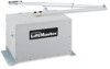
OPERATOR DIMENSIONS AND SPECIFICATIONS MODEL SW470 • 1/2 HP Motor Maximum Gate Weight - 500 lbs. (226.8 kg) Maximum Gate Width - 12 ft. (3.7 m) 6.81" (17.3 cm) 24.25" (61.6 cm) 20" (50.8 cm) 10" (25.4 cm) ...14.25" (36.2 cm) 13.38" (34 cm) 13.63" (34.6 cm) 13" (33 cm) MODEL SW490 • 1/2 HP Motor Maximum Gate Weight - 750 lbs. (340.2 kg) Maximum Gate Width - 16 ft. (4.9 m) • 3/4 HP Motor Maximum Gate Weight - 900 lbs. (408.2 kg) Maximum Gate Width - 19 ft. (5.8 m) • 1 HP...
OPERATOR DIMENSIONS AND SPECIFICATIONS MODEL SW470 • 1/2 HP Motor Maximum Gate Weight - 500 lbs. (226.8 kg) Maximum Gate Width - 12 ft. (3.7 m) 6.81" (17.3 cm) 24.25" (61.6 cm) 20" (50.8 cm) 10" (25.4 cm) ...14.25" (36.2 cm) 13.38" (34 cm) 13.63" (34.6 cm) 13" (33 cm) MODEL SW490 • 1/2 HP Motor Maximum Gate Weight - 750 lbs. (340.2 kg) Maximum Gate Width - 16 ft. (4.9 m) • 3/4 HP Motor Maximum Gate Weight - 900 lbs. (408.2 kg) Maximum Gate Width - 19 ft. (5.8 m) • 1 HP...
SW490 GL BOARD Manual
Page 4
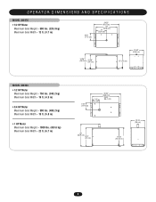
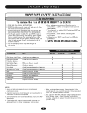
...UL325 for a control requiring continuous pressure to warn pedestrians of the dangers of motorized gate systems. Moving Gate Can Cause Injury or Death KEEP CLEAR! The opener ...area associated therewith. Type E: Built-in the gate area. UL325 MODEL CLASSIFICATIONS The SW470 and SW490 are the six types of entrapment protection systems recognized by security personnel. ... Installation Class Class I - CLASS II - SAFETY ACCESSORY SELECTION All UL325 compliant LiftMaster gate operators will accept external entrapment protection devices to complete a proper installation you ...
...UL325 for a control requiring continuous pressure to warn pedestrians of the dangers of motorized gate systems. Moving Gate Can Cause Injury or Death KEEP CLEAR! The opener ...area associated therewith. Type E: Built-in the gate area. UL325 MODEL CLASSIFICATIONS The SW470 and SW490 are the six types of entrapment protection systems recognized by security personnel. ... Installation Class Class I - CLASS II - SAFETY ACCESSORY SELECTION All UL325 compliant LiftMaster gate operators will accept external entrapment protection devices to complete a proper installation you ...
SW490 GL BOARD Manual
Page 15
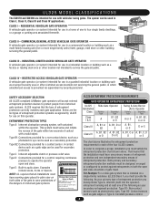
...electrical connections MUST be reviewed for suitability of wire installation. WIRE GAUGE 6 • 1/2 HP Motor ------• 3/4 HP Motor ------• 1 HP Motor --------- Upon completion of maintenance the area • ALL power wiring should be on a dedicated ... m) 1278 ft. (389.5 m) 5115 ft. (1559.1 m) 7993 ft. (2436.3 m) WIRE GAUGE 8 • 1/2 HP Motor ------• 3/4 HP Motor ------• 1 HP Motor --------- visible and clearly labeled. • Disconnecting power at that you Install an optional reversing edge BEFORE proceeding with local electrical codes. accordance...
...electrical connections MUST be reviewed for suitability of wire installation. WIRE GAUGE 6 • 1/2 HP Motor ------• 3/4 HP Motor ------• 1 HP Motor --------- Upon completion of maintenance the area • ALL power wiring should be on a dedicated ... m) 1278 ft. (389.5 m) 5115 ft. (1559.1 m) 7993 ft. (2436.3 m) WIRE GAUGE 8 • 1/2 HP Motor ------• 3/4 HP Motor ------• 1 HP Motor --------- visible and clearly labeled. • Disconnecting power at that you Install an optional reversing edge BEFORE proceeding with local electrical codes. accordance...
SW490 GL BOARD Manual
Page 18
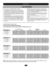
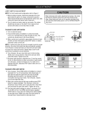
Before turning on J1 terminal strip to cause the gate to operator. CAUTION When following limit switch adjustment procedure, the motor belt will move far enough to stop control arm. Press CLOSE button (if installed) or connect terminals 4 & 5 on power, disconnect extension arm from close limit ...
Before turning on J1 terminal strip to cause the gate to operator. CAUTION When following limit switch adjustment procedure, the motor belt will move far enough to stop control arm. Press CLOSE button (if installed) or connect terminals 4 & 5 on power, disconnect extension arm from close limit ...

SW490 GL BOARD Manual
Page 23
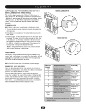
CONTROL BOARD ILLUSTRATION Main Terminal Wiring J4 Connector Master/Second Dip Switch #4 Master/Second Potentiometer Timer-to-Close Potentiometer Force Adjustment Dip Switch #2 Dip Switch #1 Diagnostic LED J2 Connector J5 Connector SAMS Relay Drive Troubleshooting LEDs J1 Terminal Troubleshooting LEDs Limit LEDs Programming Port (factory use only) Motor Learn Button J3 Connector Aux. Relay Drive (not used) 23
CONTROL BOARD ILLUSTRATION Main Terminal Wiring J4 Connector Master/Second Dip Switch #4 Master/Second Potentiometer Timer-to-Close Potentiometer Force Adjustment Dip Switch #2 Dip Switch #1 Diagnostic LED J2 Connector J5 Connector SAMS Relay Drive Troubleshooting LEDs J1 Terminal Troubleshooting LEDs Limit LEDs Programming Port (factory use only) Motor Learn Button J3 Connector Aux. Relay Drive (not used) 23
SW490 GL BOARD Manual
Page 24
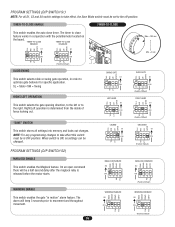
...sensed Control Input 2 Double entrapment Hard Input* 3 Failed or no hall effect sensor Removal of problem 4 Exceed maximum motor Hard Input* run mode On No Flash Motor not learned Completion of times the LED is preprogrammed at factory. If either the hard open or the hard close limits... are illuminated when the limit switch contacts are three diagnostic LEDs. The LED is reached. This is learned. If this . MOTOR LEARN BUTTON Motor Learn Button (S3) FORCE CONTROL Force Control Min Max NOTE: For LED location refer to differentiate between master and problem second ...
...sensed Control Input 2 Double entrapment Hard Input* 3 Failed or no hall effect sensor Removal of problem 4 Exceed maximum motor Hard Input* run mode On No Flash Motor not learned Completion of times the LED is preprogrammed at factory. If either the hard open or the hard close limits... are illuminated when the limit switch contacts are three diagnostic LEDs. The LED is reached. This is learned. If this . MOTOR LEARN BUTTON Motor Learn Button (S3) FORCE CONTROL Force Control Min Max NOTE: For LED location refer to differentiate between master and problem second ...
SW490 GL BOARD Manual
Page 26
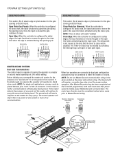
... gate "in conjunction with the potentiometer located on the board. The alarm will be a half second delay after the maglock relay is released before the motor starts. "SAVE" SWITCH This switch stores all S1, S2 and S4 switch settings to take effect this switch must be set to optimize gate behavior...
... gate "in conjunction with the potentiometer located on the board. The alarm will be a half second delay after the maglock relay is released before the motor starts. "SAVE" SWITCH This switch stores all S1, S2 and S4 switch settings to take effect this switch must be set to optimize gate behavior...
SW490 GL BOARD Manual
Page 27
... Pair) Earthground Rod (One Side Only) Shadow Loop Safety Loop COMPLEX OR PARKING LOT Conduit 27 NOTE: Timer-to initiate proper Master/Second communication. The motor learn function must have their power cycled to -Close will require a normally close cycle. Close Edge: When the controller is configured for proper system operation...
... Pair) Earthground Rod (One Side Only) Shadow Loop Safety Loop COMPLEX OR PARKING LOT Conduit 27 NOTE: Timer-to initiate proper Master/Second communication. The motor learn function must have their power cycled to -Close will require a normally close cycle. Close Edge: When the controller is configured for proper system operation...

SW490 GL BOARD Manual
Page 28
.... Improper J4 Connector Wiring (Master/Second). Make sure that the operator's belt/drive chain is a control board next to learn the motor. Measure the voltage at the operator should be within 5% of the control board. Measure the voltage at the unit's on the transformer...the green LED is in voltage. If operator is off switch as well as the meter base or sub panel. Examine the motor's labels for the distance between breaker and operator by consulting the wiring specifications section on /off switch. TROUBLESHOOTING SYMPTOM Operator fails to...
.... Improper J4 Connector Wiring (Master/Second). Make sure that the operator's belt/drive chain is a control board next to learn the motor. Measure the voltage at the operator should be within 5% of the control board. Measure the voltage at the unit's on the transformer...the green LED is in voltage. If operator is off switch as well as the meter base or sub panel. Examine the motor's labels for the distance between breaker and operator by consulting the wiring specifications section on /off switch. TROUBLESHOOTING SYMPTOM Operator fails to...
SW490 GL BOARD Manual
Page 30
...taken at the operator. Pick up any major drive chain adjustments. 4 If lubricating chain, use only a proper chain lube spray or a lightweight motor oil. Pedestrians MUST use grease or silicone spray. 5. Never use ONE SHOULD CROSS THE PATH OF THE MOVING GATE. It is suggested that the...gate operator monthly. the non-contact sensors. ALL maintenance MUST be reset after any debris in the area. Failure to be performed by a LiftMaster limit of the operators rating. 30 Use the emergency release only when the gate is within ten percent of travel, retest the gate operator....
...taken at the operator. Pick up any major drive chain adjustments. 4 If lubricating chain, use only a proper chain lube spray or a lightweight motor oil. Pedestrians MUST use grease or silicone spray. 5. Never use ONE SHOULD CROSS THE PATH OF THE MOVING GATE. It is suggested that the...gate operator monthly. the non-contact sensors. ALL maintenance MUST be reset after any debris in the area. Failure to be performed by a LiftMaster limit of the operators rating. 30 Use the emergency release only when the gate is within ten percent of travel, retest the gate operator....
SW490 GL BOARD Manual
Page 31
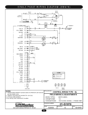
... SEE NOTE 2 R 2 SEE NOTE 4 ALARM ASSY 76-G0564 "A" LIMIT CONTACTOR A RPM - GL FIELD WIRING & ADJUSTMENTS MODEL TYPES: HORSEPOWER: VOLTAGE/PHASE: SW470 (MSW) 1/2 115V & 230V, 50/60Hz - 1 PHASE ONLY 845 Larch Avenue, Elmhurst, IL 60125 DRAWING NUMBER: DATE: 7/29/03 01-G1978 REVISION: ...OPTIONAL WIRE HARNESS. 4) (B+) AND (B-) ARE 100dB SAFETY ALARMS. APPLICATIONS: CONTROL WIRING TYPE - SINGLE PHASE WIRING DIAGRAM (SW470) 1 PHASE POWER IN SWITCH NOTE 1 MOTOR GROUND GL CONTROL BOARD J2 PLUG 24 Vac - COMMON DC - SUPPLY RPM GND RPM SENSOR RADIO COMMAND J2 PLUG SHADOW ...
... SEE NOTE 2 R 2 SEE NOTE 4 ALARM ASSY 76-G0564 "A" LIMIT CONTACTOR A RPM - GL FIELD WIRING & ADJUSTMENTS MODEL TYPES: HORSEPOWER: VOLTAGE/PHASE: SW470 (MSW) 1/2 115V & 230V, 50/60Hz - 1 PHASE ONLY 845 Larch Avenue, Elmhurst, IL 60125 DRAWING NUMBER: DATE: 7/29/03 01-G1978 REVISION: ...OPTIONAL WIRE HARNESS. 4) (B+) AND (B-) ARE 100dB SAFETY ALARMS. APPLICATIONS: CONTROL WIRING TYPE - SINGLE PHASE WIRING DIAGRAM (SW470) 1 PHASE POWER IN SWITCH NOTE 1 MOTOR GROUND GL CONTROL BOARD J2 PLUG 24 Vac - COMMON DC - SUPPLY RPM GND RPM SENSOR RADIO COMMAND J2 PLUG SHADOW ...
SW490 GL BOARD Manual
Page 32
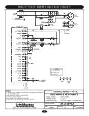
... J2 PLUG (GY) (Y) SOFT OPEN NC "B" LIMIT CONTACTOR B "A" LIMIT CONTACTOR A SEE NOTE 2 230V ONLY SEE NOTE 5 SEE NOTE 1 (W) PRIMARY R1 (BL) 24V Sec. 115 VOLT MOTOR CONNECTION 115 ONLY SEE NOTE 5 (Y) R2 (BK) B- LOOP OBS. CLOSE 24 Vac - GND LOCK 1 LOCK 2 ALARM 1 ALARM 1 1 2 J4 DUAL GATE RPM SENSOR R4 B+ ALARM ASSY... Larch Avenue, Elmhurst, IL 60125 DRAWING NUMBER: DATE: 7/29/03 01-G1979-1 REVISION: E ECN: 03-0401 32 ALARM ASSY 76-G0564 SEE NOTE 4 (Y) 230 VOLT MOTOR CONNECTION (Y) RPM -
... J2 PLUG (GY) (Y) SOFT OPEN NC "B" LIMIT CONTACTOR B "A" LIMIT CONTACTOR A SEE NOTE 2 230V ONLY SEE NOTE 5 SEE NOTE 1 (W) PRIMARY R1 (BL) 24V Sec. 115 VOLT MOTOR CONNECTION 115 ONLY SEE NOTE 5 (Y) R2 (BK) B- LOOP OBS. CLOSE 24 Vac - GND LOCK 1 LOCK 2 ALARM 1 ALARM 1 1 2 J4 DUAL GATE RPM SENSOR R4 B+ ALARM ASSY... Larch Avenue, Elmhurst, IL 60125 DRAWING NUMBER: DATE: 7/29/03 01-G1979-1 REVISION: E ECN: 03-0401 32 ALARM ASSY 76-G0564 SEE NOTE 4 (Y) 230 VOLT MOTOR CONNECTION (Y) RPM -
SW490 GL BOARD Manual
Page 33
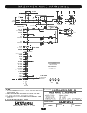
... VOLTAGE 24V SECONDARY 60VA. 2) WIRE COLOR: 208V RED, 230V ORANGE, 460V VIOLET, 575V GRAY 3) OPTIONAL WIRE HARNESS (SEE DRAWING 90-G0532). 4) OVERLOAD PROTECTION EITHER IN MOTOR OR FROM AN EXTERNAL OVERLOAD. 5) (B+) AND (B-) ARE 100dB SAFETY ALARMS. APPLICATIONS: CONTROL WIRING TYPE - OPEN OBS. ALARM ASSY 76-G0564 B- 460V...
... VOLTAGE 24V SECONDARY 60VA. 2) WIRE COLOR: 208V RED, 230V ORANGE, 460V VIOLET, 575V GRAY 3) OPTIONAL WIRE HARNESS (SEE DRAWING 90-G0532). 4) OVERLOAD PROTECTION EITHER IN MOTOR OR FROM AN EXTERNAL OVERLOAD. 5) (B+) AND (B-) ARE 100dB SAFETY ALARMS. APPLICATIONS: CONTROL WIRING TYPE - OPEN OBS. ALARM ASSY 76-G0564 B- 460V...
SW490 GL BOARD Manual
Page 35
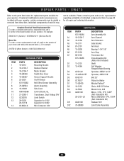
...75-G0089 DESCRIPTION Arm Assembly Kit Arm Channel Arm Extension Gate Bracket Arm Hub Bearing 1-1/4" 1/8" Arm Stop Tinnerman Nut Drive Assembly Kit (Motor Not Included) Shaft Self Aligning Flanged Mount Bearing Sprocket, 40B42 1x1/4" Sprocket, 40B12 5/8" Belt 25" Pulley for your operator, certain ...components may not be added or removed from these lists. SW470 Refer to the number of individual components. REPAIR PARTS - For example: SW420-33-11 (Operator) = K73SW420-33-11 (Electrical Box Kit) Motor Kits To order a motor replacement kit, add a K prefix to the parts lists below...
...75-G0089 DESCRIPTION Arm Assembly Kit Arm Channel Arm Extension Gate Bracket Arm Hub Bearing 1-1/4" 1/8" Arm Stop Tinnerman Nut Drive Assembly Kit (Motor Not Included) Shaft Self Aligning Flanged Mount Bearing Sprocket, 40B42 1x1/4" Sprocket, 40B12 5/8" Belt 25" Pulley for your operator, certain ...components may not be added or removed from these lists. SW470 Refer to the number of individual components. REPAIR PARTS - For example: SW420-33-11 (Operator) = K73SW420-33-11 (Electrical Box Kit) Motor Kits To order a motor replacement kit, add a K prefix to the parts lists below...
SW490 GL BOARD Manual
Page 37
...with your operator. Refer to the parts lists below for replacement parts available for all repair part ordering information. For example: 20-5752-33 (Motor Number) = K20-575233 (Motor Kit) ITEM 1 2 3 4 5 6 7 8 INDIVIDUAL PARTS PART# 10-18458 10-2013 73-18457 10-G0326 23-3001 23-...Extension Arm Galvanized Tube 39" OD 1" IDx1.315" Sleeve Bearing Actuator Arm Stop 06-2025-T Actuator Arm Assembly K75-18367 Drive Assembly Kit (Motor Not Included) 10-2008 Switch Bracket 10-G0539 Sensor Bracket Output Shaft* 12-2125 Flange Ball Bearing 1-1/4" Bore G152002 Sprocket, 50B60 1-1/2x3/8...
...with your operator. Refer to the parts lists below for replacement parts available for all repair part ordering information. For example: 20-5752-33 (Motor Number) = K20-575233 (Motor Kit) ITEM 1 2 3 4 5 6 7 8 INDIVIDUAL PARTS PART# 10-18458 10-2013 73-18457 10-G0326 23-3001 23-...Extension Arm Galvanized Tube 39" OD 1" IDx1.315" Sleeve Bearing Actuator Arm Stop 06-2025-T Actuator Arm Assembly K75-18367 Drive Assembly Kit (Motor Not Included) 10-2008 Switch Bracket 10-G0539 Sensor Bracket Output Shaft* 12-2125 Flange Ball Bearing 1-1/4" Bore G152002 Sprocket, 50B60 1-1/2x3/8...

SW490 GL BOARD Manual
Page 39
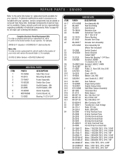
... FOR SECONDARY ENTRAPMENT PROTECTION The following devices are acceptable for Safety Accessories for gates. Miller MG020 2-wire electric edge for gates. SW490 PART 20-XXXX (Motor) 23-XXXX (Switch) 24-XXX-X (Relay) 25-20XX (Overload) 25-40XX (Overload) PART NO. 20-1050-1T 20-1075-1T 20-1100B-2T 20-3050...
... FOR SECONDARY ENTRAPMENT PROTECTION The following devices are acceptable for Safety Accessories for gates. Miller MG020 2-wire electric edge for gates. SW490 PART 20-XXXX (Motor) 23-XXXX (Switch) 24-XXX-X (Relay) 25-20XX (Overload) 25-40XX (Overload) PART NO. 20-1050-1T 20-1075-1T 20-1100B-2T 20-3050...

SW490 S3 BOARD Manual
Page 10
... 475 300 200 125 325 225 150 100 250 150 100 75 230 VAC 230 VAC 460 VAC Maximum wire length in feet for 1/3 HP motor 3,100 4,750 14,225 1,950 3,000 8,975 1,225 1,900 5,650 775 1,175 3,525 Maximum wire length in feet for ½ HP... 2,050 7,125 800 1,300 4,500 500 825 2,825 325 525 1,775 Maximum wire length in feet for 1 hp motors 950 1,425 5,700 600 900 3,600 375 575 2,275 250 375 1,425 Table 5: Power Wiring Chart 575 VAC 35,550 22,425 14,075 8,825 ...
... 475 300 200 125 325 225 150 100 250 150 100 75 230 VAC 230 VAC 460 VAC Maximum wire length in feet for 1/3 HP motor 3,100 4,750 14,225 1,950 3,000 8,975 1,225 1,900 5,650 775 1,175 3,525 Maximum wire length in feet for ½ HP... 2,050 7,125 800 1,300 4,500 500 825 2,825 325 525 1,775 Maximum wire length in feet for 1 hp motors 950 1,425 5,700 600 900 3,600 375 575 2,275 250 375 1,425 Table 5: Power Wiring Chart 575 VAC 35,550 22,425 14,075 8,825 ...
SW490 S3 BOARD Manual
Page 23
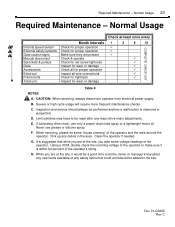
E. Never use only a proper chain lube spray or a lightweight motor oil. It is suggested that could and should always be a good time to let the owner or manager know about any new items available or ...
E. Never use only a proper chain lube spray or a lightweight motor oil. It is suggested that could and should always be a good time to let the owner or manager know about any new items available or ...
SW490 S3 BOARD Manual
Page 24
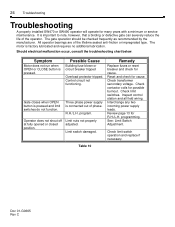
.... Operator does not shout off at fully opened or closed position. R.H./L.H. Check contactor coils for cause. Table 10 Doc 01-G0665 Rev C The motor is pressed. Three phase power supply is pressed and limit switches do not function. program. Reset and check for possible burnout. Review page 13 for... Cause Building fuse blown or circuit breaker tripped Overload protector tripped. All operator bearings are of the operator. 24 Troubleshooting Troubleshooting A properly installed SW470 or SW490 operator will operate for many years with a minimum or service maintenance.
.... Operator does not shout off at fully opened or closed position. R.H./L.H. Check contactor coils for cause. Table 10 Doc 01-G0665 Rev C The motor is pressed. Three phase power supply is pressed and limit switches do not function. program. Reset and check for possible burnout. Review page 13 for... Cause Building fuse blown or circuit breaker tripped Overload protector tripped. All operator bearings are of the operator. 24 Troubleshooting Troubleshooting A properly installed SW470 or SW490 operator will operate for many years with a minimum or service maintenance.
SW490 S3 BOARD Manual
Page 26
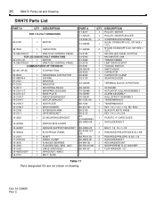
... ASSEMBLY 1 HALL EFFECT ASSEMBLY 1 TINNERMAN NUT 1 TINNERMAN NUT 1 KEY, 1/4 x 1/4 x 1 1/4: RD. 26 SW470 Parts List and Drawing SW470 Parts List PART # QTY DESCRIPTION FOR 115 VOLT OPERATORS 20-2100 1 MOTOR 29-3530 1 CAPACITOR 74-SW4705011 1 SW470 S3 CONTROL PANEL FOR 230 50/60 HZ VOLT OPERATORS 20-2101-LD... 1 MOTOR 74-SW4705021 1 SW470 S3 CONTROL PANEL COMMON PARTS OF THE SW470 02-401-SP (N) 1 STOP BUTTON 03-8024 ...
... ASSEMBLY 1 HALL EFFECT ASSEMBLY 1 TINNERMAN NUT 1 TINNERMAN NUT 1 KEY, 1/4 x 1/4 x 1 1/4: RD. 26 SW470 Parts List and Drawing SW470 Parts List PART # QTY DESCRIPTION FOR 115 VOLT OPERATORS 20-2100 1 MOTOR 29-3530 1 CAPACITOR 74-SW4705011 1 SW470 S3 CONTROL PANEL FOR 230 50/60 HZ VOLT OPERATORS 20-2101-LD... 1 MOTOR 74-SW4705021 1 SW470 S3 CONTROL PANEL COMMON PARTS OF THE SW470 02-401-SP (N) 1 STOP BUTTON 03-8024 ...


