SW490 GL BOARD Manual
Page 1
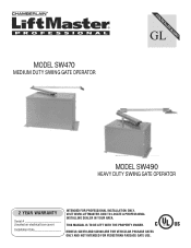
VISIT WWW.LIFTMASTER.COM TO LOCATE A PROFESSIONAL INSTALLING DEALER IN YOUR AREA. THIS MANUAL IS TO BE LEFT WITH THE PROPERTY OWNER. MODELS SW470 AND SW490 ARE FOR VEHICULAR PASSAGE GATES ONLY AND NOT INTENDED FOR PEDESTRIAN PASSAGE GATE USE. MODEL SW470 MEDIUM DUTY SWING GATE OPERATOR GLCONTROLLER BOARD MODEL SW490 HEAVY DUTY SWING GATE OPERATOR 2 YEAR WARRANTY Serial located on electrical box cover) Installation Date INTENDED FOR PROFESSIONAL INSTALLATION ONLY.
VISIT WWW.LIFTMASTER.COM TO LOCATE A PROFESSIONAL INSTALLING DEALER IN YOUR AREA. THIS MANUAL IS TO BE LEFT WITH THE PROPERTY OWNER. MODELS SW470 AND SW490 ARE FOR VEHICULAR PASSAGE GATES ONLY AND NOT INTENDED FOR PEDESTRIAN PASSAGE GATE USE. MODEL SW470 MEDIUM DUTY SWING GATE OPERATOR GLCONTROLLER BOARD MODEL SW490 HEAVY DUTY SWING GATE OPERATOR 2 YEAR WARRANTY Serial located on electrical box cover) Installation Date INTENDED FOR PROFESSIONAL INSTALLATION ONLY.
SW490 GL BOARD Manual
Page 2
...warnings carefully. HARDWARE KITS SAAW4VT70ET(KRE77NT-SWITS47I0SO) &ENSMW4E90N(K7T7-SW490) PART NO. DESCRIPTION QTY. SW470 02-401-SP Stop Button 1 10-2108-T Arm Channel 1 10-2109 Extension Arm 1 10-2111 Gate Bracket 1 40-3505 Warning Sign 2 80-2103 Black Plastic Knob 2 82-HN38-18 ...not intended to list below for Swing and Ornamental Grill Type Gates 8 Warranty Sign Placement 8 INSTALLATION Post Mounting (SW470 9 Pad Mounting (SW470 10 Pad Mounting (SW490 11 Control Arm and Gate Bracket Installation (SW470 12 Control Arm Assembly (SW490 13-14 Manual Disconnect 14...
...warnings carefully. HARDWARE KITS SAAW4VT70ET(KRE77NT-SWITS47I0SO) &ENSMW4E90N(K7T7-SW490) PART NO. DESCRIPTION QTY. SW470 02-401-SP Stop Button 1 10-2108-T Arm Channel 1 10-2109 Extension Arm 1 10-2111 Gate Bracket 1 40-3505 Warning Sign 2 80-2103 Black Plastic Knob 2 82-HN38-18 ...not intended to list below for Swing and Ornamental Grill Type Gates 8 Warranty Sign Placement 8 INSTALLATION Post Mounting (SW470 9 Pad Mounting (SW470 10 Pad Mounting (SW490 11 Control Arm and Gate Bracket Installation (SW470 12 Control Arm Assembly (SW490 13-14 Manual Disconnect 14...
SW490 GL BOARD Manual
Page 3
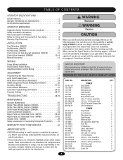
OPERATOR DIMENSIONS AND SPECIFICATIONS MODEL SW470 • 1/2 HP Motor Maximum Gate Weight - 500 lbs. (226.8 kg) Maximum Gate Width - 12 ft. (3.7 m) 6.81" (17.3 cm) 24.25" (61.6 cm) 20" (50.8 cm) 10" (25.4 cm) 14.25" (36.2 cm) 13.38" (34 cm) ...) 13" (33 cm) MODEL SW490 • 1/2 HP Motor Maximum Gate Weight - 750 lbs. (340.2 kg) Maximum Gate Width - 16 ft. (4.9 m) • 3/4 HP Motor Maximum Gate Weight - 900 lbs. (408.2 kg) Maximum Gate Width - 19 ft. (5.8 m) • 1 HP Motor Maximum Gate Weight - 1000 lbs. (453.6 kg) Maximum Gate Width - 22 ft. (6.7 m) 7.03" (17.9 cm) 7.12" (18...
OPERATOR DIMENSIONS AND SPECIFICATIONS MODEL SW470 • 1/2 HP Motor Maximum Gate Weight - 500 lbs. (226.8 kg) Maximum Gate Width - 12 ft. (3.7 m) 6.81" (17.3 cm) 24.25" (61.6 cm) 20" (50.8 cm) 10" (25.4 cm) 14.25" (36.2 cm) 13.38" (34 cm) ...) 13" (33 cm) MODEL SW490 • 1/2 HP Motor Maximum Gate Weight - 750 lbs. (340.2 kg) Maximum Gate Width - 16 ft. (4.9 m) • 3/4 HP Motor Maximum Gate Weight - 900 lbs. (408.2 kg) Maximum Gate Width - 19 ft. (5.8 m) • 1 HP Motor Maximum Gate Weight - 1000 lbs. (453.6 kg) Maximum Gate Width - 22 ft. (6.7 m) 7.03" (17.9 cm) 7.12" (18...
SW490 GL BOARD Manual
Page 4
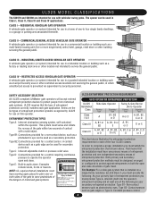
... A, B1, B2, A, B1, C or A, B1, C, D D or E D or E The chart above . CLASS IV - SAFETY ACCESSORY SELECTION All UL325 compliant LiftMaster gate operators will accept external entrapment protection devices to service the general public. This system must sense and initiate the reverse of the... or parking area associated therewith. RESTRICTED ACCESS VEHICULAR GATE OPERATOR A vehicular gate operator (or system) intended for use on both the open and close directions of gate travel. UL325 MODEL CLASSIFICATIONS The SW470 and SW490 are the six types of entrapment protection...
... A, B1, B2, A, B1, C or A, B1, C, D D or E D or E The chart above . CLASS IV - SAFETY ACCESSORY SELECTION All UL325 compliant LiftMaster gate operators will accept external entrapment protection devices to service the general public. This system must sense and initiate the reverse of the... or parking area associated therewith. RESTRICTED ACCESS VEHICULAR GATE OPERATOR A vehicular gate operator (or system) intended for use on both the open and close directions of gate travel. UL325 MODEL CLASSIFICATIONS The SW470 and SW490 are the six types of entrapment protection...
SW490 GL BOARD Manual
Page 5
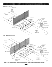
... Telephone Entry System STREET Interrupt (Safety) Loop Photo eye for close cycle DUAL SWING GATE SYSTEM Photo eye for open cycle Shadow Loop Interrupt (Safety) Loop 4' (1.2 m) Typical COMPLEX OR PARKING LOT Run twisted wire* from loop to operator Seal...37 mm) Loop Wire* Layer 1/4" (6 mm) or larger depending on loop wire size STREET InLteororuppt (Safety) Photo eye for open cycle Gate 2 Run twisted wire* from loop to operator Seal Loops* Gate 1 Photo eye for open cycle Photo eye for close cycle Shadow Loop InLteororuppt (Safety) 4' (1.2 m) Typical COMPLEX OR PARKING LOT 1-1/2" ...
... Telephone Entry System STREET Interrupt (Safety) Loop Photo eye for close cycle DUAL SWING GATE SYSTEM Photo eye for open cycle Shadow Loop Interrupt (Safety) Loop 4' (1.2 m) Typical COMPLEX OR PARKING LOT Run twisted wire* from loop to operator Seal...37 mm) Loop Wire* Layer 1/4" (6 mm) or larger depending on loop wire size STREET InLteororuppt (Safety) Photo eye for open cycle Gate 2 Run twisted wire* from loop to operator Seal Loops* Gate 1 Photo eye for open cycle Photo eye for close cycle Shadow Loop InLteororuppt (Safety) 4' (1.2 m) Typical COMPLEX OR PARKING LOT 1-1/2" ...
SW490 GL BOARD Manual
Page 6
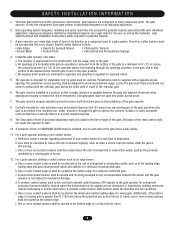
...located where the transmission of force in its wiring arranged so the communication between the gate and adjacent structures when opening shall be located in its arc of travel of a swing gate. Gate systems design and installation must be designed to operate the controls. The operator is specifically... regarding placement of non-contact sensor for the user as well as when a vehicle trips the sensor while the gate is prevented from passing through the gate to promote pedestrian usage. One or more contact sensors shall be properly installed and work freely in the open into...
...located where the transmission of force in its wiring arranged so the communication between the gate and adjacent structures when opening shall be located in its arc of travel of a swing gate. Gate systems design and installation must be designed to operate the controls. The operator is specifically... regarding placement of non-contact sensor for the user as well as when a vehicle trips the sensor while the gate is prevented from passing through the gate to promote pedestrian usage. One or more contact sensors shall be properly installed and work freely in the open into...
SW490 GL BOARD Manual
Page 7
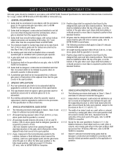
...guarded or covered. 3.2.2 Positive stops shall be required to limit travel to the designed fully open and fully closed positions. GATE CONSTRUCTION INFORMATION Vehicular gates should be installed in accordance with ASTM F2200: Standard Specification for Exception. 3.1.4 Positive stops shall be required to limit ...the adjacent fence that covers in the open position. 3.1.3 A gap, measured in the horizontal plane parallel to the roadway, between the gate and the supporting structure or other than the exceptions listed in ASTM F2200. 1.4 The minimum height for barbed tape shall not be ...
...guarded or covered. 3.2.2 Positive stops shall be required to limit travel to the designed fully open and fully closed positions. GATE CONSTRUCTION INFORMATION Vehicular gates should be installed in accordance with ASTM F2200: Standard Specification for Exception. 3.1.4 Positive stops shall be required to limit ...the adjacent fence that covers in the open position. 3.1.3 A gap, measured in the horizontal plane parallel to the roadway, between the gate and the supporting structure or other than the exceptions listed in ASTM F2200. 1.4 The minimum height for barbed tape shall not be ...
SW490 GL BOARD Manual
Page 8
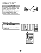
... only Pedestrians must use separate entrance 8 AVERTISSEMENT WARNING SIGN PALATCTEMEENNT TION WARNING To prevent SERIOUS INJURY or DEATH from a moving gate: CAUTION • Entrapment protection devices MUST be installed to protect in a suitable manner using fastening holes. SAFETY PRECAUTIONS FOR SWING ...AND ORNAMENTAL "GRILL TYPE GATES" WARNING To prevent SERIOUS INJURY or DEATH from a moving gate: CAUTION • Install warning signs on EACH side of gate in PLAIN VIEW. • Permanently secure each warning sign in BOTH ...
... only Pedestrians must use separate entrance 8 AVERTISSEMENT WARNING SIGN PALATCTEMEENNT TION WARNING To prevent SERIOUS INJURY or DEATH from a moving gate: CAUTION • Entrapment protection devices MUST be installed to protect in a suitable manner using fastening holes. SAFETY PRECAUTIONS FOR SWING ...AND ORNAMENTAL "GRILL TYPE GATES" WARNING To prevent SERIOUS INJURY or DEATH from a moving gate: CAUTION • Install warning signs on EACH side of gate in PLAIN VIEW. • Permanently secure each warning sign in BOTH ...
SW490 GL BOARD Manual
Page 9
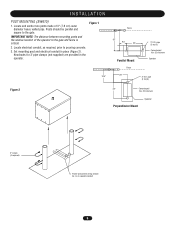
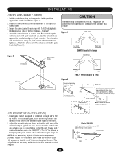
Posts should be parallel and square to the gate. Set mounting post and electrical conduit in the operator. Knockouts for 3" pipe clamps (not supplied) are provided in place (Figure 2). Figure 1 18.5" Fence 30" 9.5" 23" ... be run in separate conduit 9 Locate and anchor two posts made of the operator to pouring concrete. 3. Locate electrical conduit, as required, prior to the gate and fence is critical. 2. IMPORTANT NOTE: The distance between mounting posts and the relative location of 3" (7.6 cm) outer diameter heavy walled pipe. INSTALLATION POST MOUNTING...
Posts should be parallel and square to the gate. Set mounting post and electrical conduit in the operator. Knockouts for 3" pipe clamps (not supplied) are provided in place (Figure 2). Figure 1 18.5" Fence 30" 9.5" 23" ... be run in separate conduit 9 Locate and anchor two posts made of the operator to pouring concrete. 3. Locate electrical conduit, as required, prior to the gate and fence is critical. 2. IMPORTANT NOTE: The distance between mounting posts and the relative location of 3" (7.6 cm) outer diameter heavy walled pipe. INSTALLATION POST MOUNTING...
SW490 GL BOARD Manual
Page 10
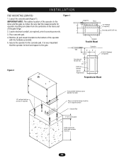
IMPORTANT NOTE: The relative location of the operator to the gate. Bolt the (2) pad mount brackets to pouring concrete. 3. Operator Parallel Mount Centerline Gate 6" 8" 18-3/4" 8"16"1/2" Redhead (4 required) Figure 2 Concrete pad 18"x34" min. 22-1/2" Profile of Operator SW470 Perpendicular Perpendicular Mount 1/2" red head bolts or anchors (4 required) Using suitable hardware secure operator to...
IMPORTANT NOTE: The relative location of the operator to the gate. Bolt the (2) pad mount brackets to pouring concrete. 3. Operator Parallel Mount Centerline Gate 6" 8" 18-3/4" 8"16"1/2" Redhead (4 required) Figure 2 Concrete pad 18"x34" min. 22-1/2" Profile of Operator SW470 Perpendicular Perpendicular Mount 1/2" red head bolts or anchors (4 required) Using suitable hardware secure operator to...
SW490 GL BOARD Manual
Page 11
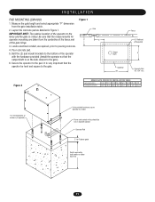
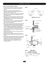
... the concrete pad as required, prior to the gate). 6. Secure the operator to the fence and the gate is critical. Measure the gate length and select appropriate "P" dimension from the centerline of the fence and of the gate hinge. 3. IMPORTANT NOTE: The relative location of... table. 2. Locate electrical conduit, as detailed in separate conduit Concrete Pad 2" to the gate. It is on the side closest to pouring concrete. 4. Pour concrete pad. 5. Figure 1 P Gate 5" Output Shaft Fence 1/2" Redhead (4 Required) 8" Operator 28" Concrete Pad 18" x 34" min. Be sure that the ...
... the concrete pad as required, prior to the gate). 6. Secure the operator to the fence and the gate is critical. Measure the gate length and select appropriate "P" dimension from the centerline of the fence and of the gate hinge. 3. IMPORTANT NOTE: The relative location of... table. 2. Locate electrical conduit, as detailed in separate conduit Concrete Pad 2" to the gate. It is on the side closest to pouring concrete. 4. Pour concrete pad. 5. Figure 1 P Gate 5" Output Shaft Fence 1/2" Redhead (4 Required) 8" Operator 28" Concrete Pad 18" x 34" min. Be sure that the ...
SW490 GL BOARD Manual
Page 12
... 3). NOTE: As an alternative, (2) 3/8-16 bolts and a nut plate are appropriate for desired degree of gate opening and damage to the right). 2. INSTALLATION WARNING CONTROL ARM ASSEMBLY (SW470) 1. Figure 2). 4. The extension arm should be prevented from opening . Attach the other end of the ... hub with spot-faced side up. Use the holes that the small thickness is installed incorrectly, the gate will provide the necessary deflection in a straight line. SW470 Perpendicular to the operator output shaft. 3. Secure the arm channel to keep the extension arm with 1/4-...
... 3). NOTE: As an alternative, (2) 3/8-16 bolts and a nut plate are appropriate for desired degree of gate opening and damage to the right). 2. INSTALLATION WARNING CONTROL ARM ASSEMBLY (SW470) 1. Figure 2). 4. The extension arm should be prevented from opening . Attach the other end of the ... hub with spot-faced side up. Use the holes that the small thickness is installed incorrectly, the gate will provide the necessary deflection in a straight line. SW470 Perpendicular to the operator output shaft. 3. Secure the arm channel to keep the extension arm with 1/4-...
SW490 GL BOARD Manual
Page 13
... testing and all final adjustment have been completed (Figure 4). Attach control arm extension to control arm hub assembly by others) gate CCoonntrtorol laramrm exetxetnensisoionn 13 Remove the open stop , as the top surface of control arm extension should be used in the ...pivot pin assembly and cotter pin (Figure 3). 9. Lock the key in place with the handling of the installation (Figure 1). 2. Install the supplied gate bracket or install your own gate bracket (recommended 2" x 2" x 1/4" angle) horizontally on the operator so that the key is not to hold pipe firmly. I N S ...
... testing and all final adjustment have been completed (Figure 4). Attach control arm extension to control arm hub assembly by others) gate CCoonntrtorol laramrm exetxetnensisoionn 13 Remove the open stop , as the top surface of control arm extension should be used in the ...pivot pin assembly and cotter pin (Figure 3). 9. Lock the key in place with the handling of the installation (Figure 1). 2. Install the supplied gate bracket or install your own gate bracket (recommended 2" x 2" x 1/4" angle) horizontally on the operator so that the key is not to hold pipe firmly. I N S ...
SW490 GL BOARD Manual
Page 14
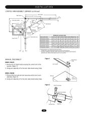
... (2) black knobs securing the control arm to pivot dimension. Gate should swing freely. MANUAL DISCONNECT MODEL SW470 1. I N S TA L L AT I O N CONTROL ARM ASSEMBLY (SW490) continued Gate Hinge Open gate position 2" 34" Closed gate stop D Control arm hub assembly Output Shaft C 13" Gate Length B A 4.5" 90º Closed gate position Pipe Gate Bracket Extension Arm Holder Control arm extension Extension Arm...
... (2) black knobs securing the control arm to pivot dimension. Gate should swing freely. MANUAL DISCONNECT MODEL SW470 1. I N S TA L L AT I O N CONTROL ARM ASSEMBLY (SW490) continued Gate Hinge Open gate position 2" 34" Closed gate stop D Control arm hub assembly Output Shaft C 13" Gate Length B A 4.5" 90º Closed gate position Pipe Gate Bracket Extension Arm Holder Control arm extension Extension Arm...
SW490 GL BOARD Manual
Page 15
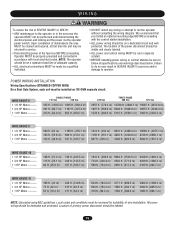
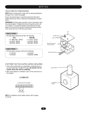
... and locking-out the power via the operator without consulting the wiring diagram. ON POWER WIRING INSTALLATION AVERTISSEMENT Wiring Specifications (STRANDED COPPER WIRE) On a Dual Gate System, each unit must be protected. WIRE GAUGE 6 • 1/2 HP Motor ------• 3/4 HP Motor ------• 1 HP Motor --------- The location of the power disconnect should be...
... and locking-out the power via the operator without consulting the wiring diagram. ON POWER WIRING INSTALLATION AVERTISSEMENT Wiring Specifications (STRANDED COPPER WIRE) On a Dual Gate System, each unit must be protected. WIRE GAUGE 6 • 1/2 HP Motor ------• 3/4 HP Motor ------• 1 HP Motor --------- The location of the power disconnect should be...
SW490 GL BOARD Manual
Page 16
...; L1 (HOT), BLACK • L2 (HOT), BLACK • GROUND, GREEN THREE PHASE All three phase operators will run reversed. Then reverse any two of the gate. This control will not function unless this situation, shut off power at main power source and at the operator's electrical disconnect switch. J1 CONNECTOR STOP...
...; L1 (HOT), BLACK • L2 (HOT), BLACK • GROUND, GREEN THREE PHASE All three phase operators will run reversed. Then reverse any two of the gate. This control will not function unless this situation, shut off power at main power source and at the operator's electrical disconnect switch. J1 CONNECTOR STOP...
SW490 GL BOARD Manual
Page 17
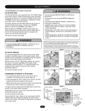
... open the front panel of receiver case with FCC Standards FOR HOME OR OFFICE USE. To prevent possible SERIOUS INJURY or DEATH from a moving gate or door. THERE ARE NO OTHER USER SERVICEABLE PARTS. Use of constant closure is factory set for each remote control. Within 30 seconds, press... any previous remote control codes must be erased. NEVER permit children to operate, or play with up to cross path of moving gate or garage door: • ALWAYS keep gate or garage door in "C" (Constant) position, the contacts will glow steadily for 30 seconds. 3. The jumper must be set at...
... open the front panel of receiver case with FCC Standards FOR HOME OR OFFICE USE. To prevent possible SERIOUS INJURY or DEATH from a moving gate or door. THERE ARE NO OTHER USER SERVICEABLE PARTS. Use of constant closure is factory set for each remote control. Within 30 seconds, press... any previous remote control codes must be erased. NEVER permit children to operate, or play with up to cross path of moving gate or garage door: • ALWAYS keep gate or garage door in "C" (Constant) position, the contacts will glow steadily for 30 seconds. 3. The jumper must be set at...
SW490 GL BOARD Manual
Page 18
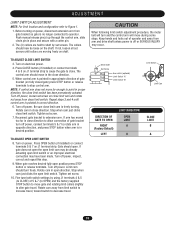
... the close limit switch. The (3) collars are moving freely on power, disconnect extension arm from limit switch to increase travel, toward switch to alter gate travel . When control arm is freely turning. Rotate cam in approximate direction of 5 & 7 (to OPEN) and the factory supplied STOP button ...to move far enough to CLOSE) of gate bracket (on power. Turn off power. Turn off power, loosen set screw. 10. TO ADJUST OPEN LIMIT SWITCH 8. Before turning on shaft. If...
... the close limit switch. The (3) collars are moving freely on power, disconnect extension arm from limit switch to increase travel, toward switch to alter gate travel . When control arm is freely turning. Rotate cam in approximate direction of 5 & 7 (to OPEN) and the factory supplied STOP button ...to move far enough to CLOSE) of gate bracket (on power. Turn off power. Turn off power, loosen set screw. 10. TO ADJUST OPEN LIMIT SWITCH 8. Before turning on shaft. If...
SW490 GL BOARD Manual
Page 20
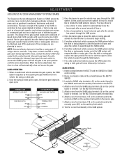
...you are planning to terminal 1 on the control board in the SW420 and locate the auxiliary limit switch in the BG770. 4. At this gate system balances the demands of speed during high traffic periods with security during high traffic times, connect the device's N/O relay output to pass ... STREET Hold Open Loop Master Second Shadow Loop Safety Loop COMPLEX OR PARKING LOT 20 Once the swing or slide gate is controlled by two gates installed in the barrier gate. 7. Once the device activates the Interrupt Loop input, the next vehicle to access the SAMS system will automatically ...
...you are planning to terminal 1 on the control board in the SW420 and locate the auxiliary limit switch in the BG770. 4. At this gate system balances the demands of speed during high traffic periods with security during high traffic times, connect the device's N/O relay output to pass ... STREET Hold Open Loop Master Second Shadow Loop Safety Loop COMPLEX OR PARKING LOT 20 Once the swing or slide gate is controlled by two gates installed in the barrier gate. 7. Once the device activates the Interrupt Loop input, the next vehicle to access the SAMS system will automatically ...
SW490 GL BOARD Manual
Page 21
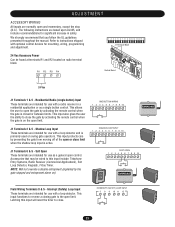
...SOFT OPEN 1 2 3 4 5 6 7 8 9 10 123 56 789 0# Field Wiring Terminals 8 & 5 - This input protects cars by activating the remote control when the gate is active. Accessories that you follow the UL guidelines presented throughout the manual. INTERRUPT (SAFETY) LOOP INPUT 5 8 9 10 11 12 FREQ FREQ FREQ 21 The... (N.C.). Refer to open limit. NOTE: Will not override a double entrapment (signalled by activating the remote control when the gate is on ). Residential Radio (single button) Input These terminals are intended for use with optional control devices for mounting, ...
...SOFT OPEN 1 2 3 4 5 6 7 8 9 10 123 56 789 0# Field Wiring Terminals 8 & 5 - This input protects cars by activating the remote control when the gate is active. Accessories that you follow the UL guidelines presented throughout the manual. INTERRUPT (SAFETY) LOOP INPUT 5 8 9 10 11 12 FREQ FREQ FREQ 21 The... (N.C.). Refer to open limit. NOTE: Will not override a double entrapment (signalled by activating the remote control when the gate is on ). Residential Radio (single button) Input These terminals are intended for use with optional control devices for mounting, ...


