
SW490 GL BOARD Manual
Page 1
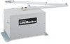
THIS MANUAL IS TO BE LEFT WITH THE PROPERTY OWNER. MODEL SW470 MEDIUM DUTY SWING GATE OPERATOR GLCONTROLLER BOARD MODEL SW490 HEAVY DUTY SWING GATE OPERATOR 2 YEAR WARRANTY Serial located on electrical box cover) Installation Date INTENDED FOR PROFESSIONAL INSTALLATION ONLY. VISIT WWW.LIFTMASTER.COM TO LOCATE A PROFESSIONAL INSTALLING DEALER IN YOUR AREA. MODELS SW470 AND SW490 ARE FOR VEHICULAR PASSAGE GATES ONLY AND NOT INTENDED FOR PEDESTRIAN PASSAGE GATE USE.
THIS MANUAL IS TO BE LEFT WITH THE PROPERTY OWNER. MODEL SW470 MEDIUM DUTY SWING GATE OPERATOR GLCONTROLLER BOARD MODEL SW490 HEAVY DUTY SWING GATE OPERATOR 2 YEAR WARRANTY Serial located on electrical box cover) Installation Date INTENDED FOR PROFESSIONAL INSTALLATION ONLY. VISIT WWW.LIFTMASTER.COM TO LOCATE A PROFESSIONAL INSTALLING DEALER IN YOUR AREA. MODELS SW470 AND SW490 ARE FOR VEHICULAR PASSAGE GATES ONLY AND NOT INTENDED FOR PEDESTRIAN PASSAGE GATE USE.
SW490 GL BOARD Manual
Page 2
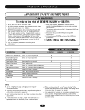
...Type Gates 8 Warranty Sign Placement 8 INSTALLATION Post Mounting (SW470 9 Pad Mounting (SW470 10 Pad Mounting (SW490 11 Control Arm and Gate Bracket Installation (SW470 12 Control Arm Assembly (SW490 13-14 Manual Disconnect 14 WIRING AVERTISSEMENT Power Wiring Installation 15 On/Off... The hazard may come from something mechanical or from electric shock. WARNING Mechanical CWWAUAATRRINNOIINNNGG Electrical CAWUATRIONNING When you see this manual and follow all safety instructions. • These instructions are not intended to highlight certain safety related issues. TABLE OF...
...Type Gates 8 Warranty Sign Placement 8 INSTALLATION Post Mounting (SW470 9 Pad Mounting (SW470 10 Pad Mounting (SW490 11 Control Arm and Gate Bracket Installation (SW470 12 Control Arm Assembly (SW490 13-14 Manual Disconnect 14 WIRING AVERTISSEMENT Power Wiring Installation 15 On/Off... The hazard may come from something mechanical or from electric shock. WARNING Mechanical CWWAUAATRRINNOIINNNGG Electrical CAWUATRIONNING When you see this manual and follow all safety instructions. • These instructions are not intended to highlight certain safety related issues. TABLE OF...
SW490 GL BOARD Manual
Page 6
... usage. One or more contact sensors shall be located where the risk of the vehicular gate. 6. Vehicular gate systems provide convenience and security. Reference owner's manual regarding placement of non-contact sensor for an individual application. 2. One or more contact sensors shall be located and its arc of the adjacent fence...
... usage. One or more contact sensors shall be located where the risk of the vehicular gate. 6. Vehicular gate systems provide convenience and security. Reference owner's manual regarding placement of non-contact sensor for an individual application. 2. One or more contact sensors shall be located and its arc of the adjacent fence...
SW490 GL BOARD Manual
Page 7
... 8 feet (2.44 m) above grade and for barbed wire shall not be less than 6 feet (1.83 m) above grade. 1.5 An existing gate latch shall be disabled when a manually operated gate is retrofitted with a powered gate operator. 1.6 A gate latch shall not be installed on an automatically operated gate. 1.7 Protrusions shall not be permitted on...
... 8 feet (2.44 m) above grade and for barbed wire shall not be less than 6 feet (1.83 m) above grade. 1.5 An existing gate latch shall be disabled when a manually operated gate is retrofitted with a powered gate operator. 1.6 A gate latch shall not be installed on an automatically operated gate. 1.7 Protrusions shall not be permitted on...
SW490 GL BOARD Manual
Page 14
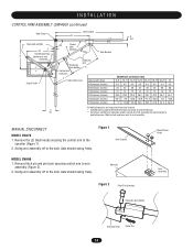
MANUAL DISCONNECT MODEL SW470 1. Swing arm assembly off to the side. Housing Black Plastic Knob Hub Assembly Figure 2 Pivot Pin Assembly Extension Arm Holder Extension Arm Cotter Pin 14 ...
MANUAL DISCONNECT MODEL SW470 1. Swing arm assembly off to the side. Housing Black Plastic Knob Hub Assembly Figure 2 Pivot Pin Assembly Extension Arm Holder Extension Arm Cotter Pin 14 ...
SW490 GL BOARD Manual
Page 18
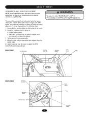
... unless power is no longer connected to stop control arm. Limit cam should now be already actuating open limit cam may have been made. Push manual release pin(s) up through the control arm, slide clevis pin in close limit switch. When control arm is pointed in correct direction. 6. Tighten set screw...
... unless power is no longer connected to stop control arm. Limit cam should now be already actuating open limit cam may have been made. Push manual release pin(s) up through the control arm, slide clevis pin in close limit switch. When control arm is pointed in correct direction. 6. Tighten set screw...
SW490 GL BOARD Manual
Page 19
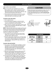
... This system consists of SEVERE INJURY or DEATH: CAUTION • Disconnect power BEFORE performing ANY adjustments. Parallel with the pulley. Manually rotate pulley to ensure that the sensor is: a. It may go out of alignment due to shipping vibration or rough handling. ..., but may become necessary to adjust the sensor for correct alignment. These operators use an internal entrapment protector system. MODEL SW470 Hall Effect Cable Mounting Screw (2) AVERTISSEMENT ATTENTION Hall Effect Bracket Pulley Magnet Pulley MODEL SW490 Mounting Screw (2) Mounting Bracket Hall...
... This system consists of SEVERE INJURY or DEATH: CAUTION • Disconnect power BEFORE performing ANY adjustments. Parallel with the pulley. Manually rotate pulley to ensure that the sensor is: a. It may go out of alignment due to shipping vibration or rough handling. ..., but may become necessary to adjust the sensor for correct alignment. These operators use an internal entrapment protector system. MODEL SW470 Hall Effect Cable Mounting Screw (2) AVERTISSEMENT ATTENTION Hall Effect Bracket Pulley Magnet Pulley MODEL SW490 Mounting Screw (2) Mounting Bracket Hall...
SW490 GL BOARD Manual
Page 21
... These terminals are intended for significant increase in a residential application or as a general open limit. Accessories that you follow the UL guidelines presented throughout the manual. This input protects cars by the gate stopped and entrapment alarm on radio terminal block. Refer to this input will reset the timer to open...
... These terminals are intended for significant increase in a residential application or as a general open limit. Accessories that you follow the UL guidelines presented throughout the manual. This input protects cars by the gate stopped and entrapment alarm on radio terminal block. Refer to this input will reset the timer to open...

SW490 GL BOARD Manual
Page 28
... drawn does not exceed the panel's rating. If all is solid the board needs to run. Measure the voltage at the top right of this manual. If the high voltage power is good and the low voltage power is bad, check to make sure there is a control board next to make.... Make sure that the proper wire gauge was used for any red LEDs are correct replace the transformer. If any distortion or signs of this manual. Measure the incoming voltage at the operator should be within 5% of the control board. Measure the voltage at the unit's on page 14 of over...
... drawn does not exceed the panel's rating. If all is solid the board needs to run. Measure the voltage at the top right of this manual. If the high voltage power is good and the low voltage power is bad, check to make sure there is a control board next to make.... Make sure that the proper wire gauge was used for any red LEDs are correct replace the transformer. If any distortion or signs of this manual. Measure the incoming voltage at the operator should be within 5% of the control board. Measure the voltage at the unit's on page 14 of over...
SW490 GL BOARD Manual
Page 30
... Check for proper adjustment X X External Entrapment Check for proper operation X X Protection Systems Gate Caution Signs Make sure they are present X X Manual Disconnect Check and operate X X Drive Chain Check for excessive slack and lubricate X X Sprockets and Pulleys Check for excessive slack and lubricate X...qualified service person make repairs to the operator it is suggested that while at the site voltage readings be performed by a LiftMaster limit of the operator and the area around the operator. the non-contact sensors. Limit switches may have to adjust ...
... Check for proper adjustment X X External Entrapment Check for proper operation X X Protection Systems Gate Caution Signs Make sure they are present X X Manual Disconnect Check and operate X X Drive Chain Check for excessive slack and lubricate X X Sprockets and Pulleys Check for excessive slack and lubricate X...qualified service person make repairs to the operator it is suggested that while at the site voltage readings be performed by a LiftMaster limit of the operator and the area around the operator. the non-contact sensors. Limit switches may have to adjust ...
SW490 GL BOARD Manual
Page 34
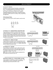
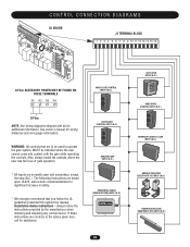
...(N.O.) OBSTRUCTION OPEN EDGE/PHOTO EYE INPUT (N.O.) OBSTRUCTION CLOSE EDGE/PHOTO EYE INPUT (N.O.) Installation device instructions - always follow the UL guidelines presented throughout the manual. CONTROL CONNECTION DIAGRAMS GL BOARD J1 TERMINAL BLOCK 1 2 3 4 5 6 7 8 9 10 11 12 13 14 15 16 24 Vac ACCESSORY...We strongly recommend that are to be installed where the user cannot come into contact with kit for additional information. See owner's manual for assistance. If these instructions are normally open and momentary, except the stop (N.C.). WARNING: All controls that you follow the...
...(N.O.) OBSTRUCTION OPEN EDGE/PHOTO EYE INPUT (N.O.) OBSTRUCTION CLOSE EDGE/PHOTO EYE INPUT (N.O.) Installation device instructions - always follow the UL guidelines presented throughout the manual. CONTROL CONNECTION DIAGRAMS GL BOARD J1 TERMINAL BLOCK 1 2 3 4 5 6 7 8 9 10 11 12 13 14 15 16 24 Vac ACCESSORY...We strongly recommend that are to be installed where the user cannot come into contact with kit for additional information. See owner's manual for assistance. If these instructions are normally open and momentary, except the stop (N.C.). WARNING: All controls that you follow the...
SW490 S3 BOARD Manual
Page 2
... Gates 8 Preparing the Installation 9 Pre-Installation Check List 9 Wiring Specifications 9 System Features 10 Installation 12 Post Mount for SW470 Operator Only 12 Pad Mount Installation 13 Control Arm Assembly 14 Gate Bracket Installation 16 Limit Switch Adjustments 17 Electrical Power Connections 18... 19 Switch #1: Operator Programming 19 Switch #2: Timer to Close 20 Controls and Accessory Installation 21 Manual Operation and System Check-Out 22 SW470 Manual Gate Operation 22 Preliminary System Check Out 22 Required Maintenance - Normal Usage 23 Troubleshooting 24...
... Gates 8 Preparing the Installation 9 Pre-Installation Check List 9 Wiring Specifications 9 System Features 10 Installation 12 Post Mount for SW470 Operator Only 12 Pad Mount Installation 13 Control Arm Assembly 14 Gate Bracket Installation 16 Limit Switch Adjustments 17 Electrical Power Connections 18... 19 Switch #1: Operator Programming 19 Switch #2: Timer to Close 20 Controls and Accessory Installation 21 Manual Operation and System Check-Out 22 SW470 Manual Gate Operation 22 Preliminary System Check Out 22 Required Maintenance - Normal Usage 23 Troubleshooting 24...
SW490 S3 BOARD Manual
Page 3
Contents 3 SW470 Parts List 26 SW490 Parts List and Drawing 27 SW490 Exploded View 27 SW490 Parts List 28 Warranty Policy 30 IMPORTANT! Doc 01-G0665 Rev C This gate operator is intended for use on a gate that swings in an arc in a horizontal plane. Please leave this manual at the job site, preferably with the end user or facility manager. Read and follow all instructions.
Contents 3 SW470 Parts List 26 SW490 Parts List and Drawing 27 SW490 Exploded View 27 SW490 Parts List 28 Warranty Policy 30 IMPORTANT! Doc 01-G0665 Rev C This gate operator is intended for use on a gate that swings in an arc in a horizontal plane. Please leave this manual at the job site, preferably with the end user or facility manager. Read and follow all instructions.
SW490 S3 BOARD Manual
Page 4
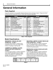
... industrial location such as a factory, loading dock area, or other locations not intended to four single family homes or its garage or parking area. MODEL SW470 SW490 CLASS 1 ! ! PART # 01-G0582 02-401-SP 10-2108-T 10-2109 10-2111 40-3505 80-2103 82-HN38-20 82-SB50-08 84...-WH-38 85-FW-38 SW470 DESCRIPTION GATE OPERATIONAL SAFETY INSTRUCTION MANUAL STOP BUTTON ARM CHANNEL EXTENSION ARM GATE BRACKET DORCMA WARNING SIGN BLACK PLASTIC KNOB 3/8-16 x 1-1/2 HEX HEAD BOLT 1/2-13 x 1/2 SHOULDER BOLT 3/8-16...
... industrial location such as a factory, loading dock area, or other locations not intended to four single family homes or its garage or parking area. MODEL SW470 SW490 CLASS 1 ! ! PART # 01-G0582 02-401-SP 10-2108-T 10-2109 10-2111 40-3505 80-2103 82-HN38-20 82-SB50-08 84...-WH-38 85-FW-38 SW470 DESCRIPTION GATE OPERATIONAL SAFETY INSTRUCTION MANUAL STOP BUTTON ARM CHANNEL EXTENSION ARM GATE BRACKET DORCMA WARNING SIGN BLACK PLASTIC KNOB 3/8-16 x 1-1/2 HEX HEAD BOLT 1/2-13 x 1/2 SHOULDER BOLT 3/8-16...
SW490 S3 BOARD Manual
Page 6
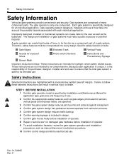
...instructions are comprised of a gate system. STEP 1: BEFORE INSTALLATION 1 Confirm gate operator model is specified by Installation and Maintenance Manual for application type, gate size and frequency of gate systems must take into every design. Improperly designed, installed or maintained systems... associated with a precautionary symbol (see left margin). The gate operator is specifically designed for the user as well as manual disconnect mechanism procedure. 10 Confirm control design prohibits unauthorized use . The design and installation of use. 2 Confirm ALL appropriate...
...instructions are comprised of a gate system. STEP 1: BEFORE INSTALLATION 1 Confirm gate operator model is specified by Installation and Maintenance Manual for application type, gate size and frequency of gate systems must take into every design. Improperly designed, installed or maintained systems... associated with a precautionary symbol (see left margin). The gate operator is specifically designed for the user as well as manual disconnect mechanism procedure. 10 Confirm control design prohibits unauthorized use . The design and installation of use. 2 Confirm ALL appropriate...
SW490 S3 BOARD Manual
Page 7
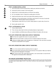
... line. 8 Secure gate operator cover. Make sure that secondary safeties always be located as shown on public side of gate system. 3 Leave Installation and Maintenance Manual and Safety Information with sensor for both . FOR GATE OPERATORS USING CONTACT SENSOR(S) One or more than one sensor should be conspicuous. 7 Install operator inside...
... line. 8 Secure gate operator cover. Make sure that secondary safeties always be located as shown on public side of gate system. 3 Leave Installation and Maintenance Manual and Safety Information with sensor for both . FOR GATE OPERATORS USING CONTACT SENSOR(S) One or more than one sensor should be conspicuous. 7 Install operator inside...
SW490 S3 BOARD Manual
Page 11
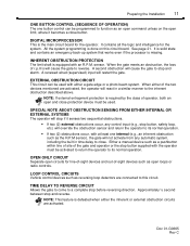
... normal operation. All the system programming is missing. EXTERNAL OBSTRUCTION CIRCUIT This circuit can be activated to return the operator to its normal operation. Either a manual device such as an open command unless on this circuit. Approximately ½ second between stop and reverse. It is solid state and contains an emergency...
... normal operation. All the system programming is missing. EXTERNAL OBSTRUCTION CIRCUIT This circuit can be activated to return the operator to its normal operation. Either a manual device such as an open command unless on this circuit. Approximately ½ second between stop and reverse. It is solid state and contains an emergency...
SW490 S3 BOARD Manual
Page 21
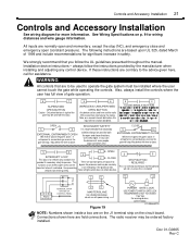
... Will reverse (close directions. OPEN 3 2 E- For warning devices, call for both the open ) the gate if active. always follow the UL guidelines presented throughout the manual. If entrapment is sensed during a reversal the gate will stop . Figure 19 13 14 POWER GATE LOCK USE POWER TO MATCH GATE LOCK REQUIREMENTS, NOT...
... Will reverse (close directions. OPEN 3 2 E- For warning devices, call for both the open ) the gate if active. always follow the UL guidelines presented throughout the manual. If entrapment is sensed during a reversal the gate will stop . Figure 19 13 14 POWER GATE LOCK USE POWER TO MATCH GATE LOCK REQUIREMENTS, NOT...
SW490 S3 BOARD Manual
Page 22
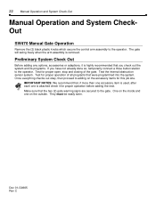
... Rev C Once everything checks out okay, then proceed to the operator. Test for proper operation before adding the next. 22 Manual Operation and System Check-Out Manual Operation and System CheckOut SW470 Manual Gate Operation Remove the (2) black plastic knobs which secure the control arm assembly to the gate. The gate will swing freely...
... Rev C Once everything checks out okay, then proceed to the operator. Test for proper operation before adding the next. 22 Manual Operation and System Check-Out Manual Operation and System CheckOut SW470 Manual Gate Operation Remove the (2) black plastic knobs which secure the control arm assembly to the gate. The gate will swing freely...
SW490 S3 BOARD Manual
Page 23
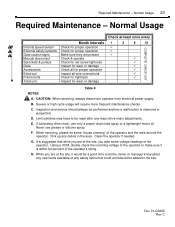
Normal Usage Internal speed sensor External safety systems Gate caution signs Manual disconnect Sprockets & pulleys Gate Accessories Electrical Frame bolts Total unit Month Intervals Check for proper operation Check for proper operation Make sure they are present ...
Normal Usage Internal speed sensor External safety systems Gate caution signs Manual disconnect Sprockets & pulleys Gate Accessories Electrical Frame bolts Total unit Month Intervals Check for proper operation Check for proper operation Make sure they are present ...


