SW490 GL BOARD Manual
Page 2
... MAINTENANCE Operator Maintenance 30 Single Phase Wiring Diagram (SW470 31 Single Phase Wiring Diagram (SW490 32 Three Phase Wiring Diagram (SW490 33 Control Connection Diagrams 34 Repair Parts and Illustrated Parts - SW490 37-38 Variable Parts - These instructions are intended to your gate and/or the gate AVERTISSEMENT operator if you do not comply with the...
... MAINTENANCE Operator Maintenance 30 Single Phase Wiring Diagram (SW470 31 Single Phase Wiring Diagram (SW490 32 Three Phase Wiring Diagram (SW490 33 Control Connection Diagrams 34 Repair Parts and Illustrated Parts - SW490 37-38 Variable Parts - These instructions are intended to your gate and/or the gate AVERTISSEMENT operator if you do not comply with the...
SW490 GL BOARD Manual
Page 6
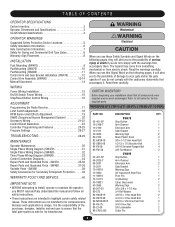
...adjacent fence that transmits radio frequency (RF) signals to the gate operator for user activation must be designed to a minimum of 4' (1.2 m) above the ground at any moving part of a vehicular horizontal slide gate. Pedestrians must be located where the risk of entrapment or...'s manual regarding placement of non-contact sensor for the user as well as a component part of many component parts. c. The pedestrian access opening and closing to the installation of the gate operator. 8 Controls intended for entrapment protection functions shall be located at the bottom edge...
...adjacent fence that transmits radio frequency (RF) signals to the gate operator for user activation must be designed to a minimum of 4' (1.2 m) above the ground at any moving part of a vehicular horizontal slide gate. Pedestrians must be located where the risk of entrapment or...'s manual regarding placement of non-contact sensor for the user as well as a component part of many component parts. c. The pedestrian access opening and closing to the installation of the gate operator. 8 Controls intended for entrapment protection functions shall be located at the bottom edge...
SW490 GL BOARD Manual
Page 17
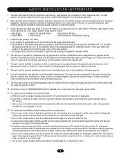
... interference that may not cause harmful interference, and (2) this receiver and/or transmitter are now erased. THERE ARE NO OTHER USER SERVICEABLE PARTS. When changing from electrocution: • Be sure power is PROHIBITED. ATTENTIONWARNING To prevent possible SERIOUS INJURY or DEATH, the use of ...PINs in HIGH security mode. With the jumper in the Programming Section below to Comply with remote control transmitters. • Activate gate or door ONLY when it overrides the safety reversal devices. The opener will close for changing the code setting or replacing the ...
... interference that may not cause harmful interference, and (2) this receiver and/or transmitter are now erased. THERE ARE NO OTHER USER SERVICEABLE PARTS. When changing from electrocution: • Be sure power is PROHIBITED. ATTENTIONWARNING To prevent possible SERIOUS INJURY or DEATH, the use of ...PINs in HIGH security mode. With the jumper in the Programming Section below to Comply with remote control transmitters. • Activate gate or door ONLY when it overrides the safety reversal devices. The opener will close for changing the code setting or replacing the ...
SW490 GL BOARD Manual
Page 35
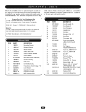
...certain components may not be added or removed from these lists. Individual components of your operator. SW470 Refer to the model number of individual components. prefix to the parts lists below for replacement parts available for all repair part ordering information. For example: 20-5752-33 (Motor Number) = K20-575233 (Motor Kit...17-G0475 19-2153 19-5040 G202100 20-2101-LD G322100 75-G0089 DESCRIPTION Arm Assembly Kit Arm Channel Arm Extension Gate Bracket Arm Hub Bearing 1-1/4" 1/8" Arm Stop Tinnerman Nut Drive Assembly Kit (Motor Not Included) Shaft Self Aligning Flanged...
...certain components may not be added or removed from these lists. Individual components of your operator. SW470 Refer to the model number of individual components. prefix to the parts lists below for replacement parts available for all repair part ordering information. For example: 20-5752-33 (Motor Number) = K20-575233 (Motor Kit...17-G0475 19-2153 19-5040 G202100 20-2101-LD G322100 75-G0089 DESCRIPTION Arm Assembly Kit Arm Channel Arm Extension Gate Bracket Arm Hub Bearing 1-1/4" 1/8" Arm Stop Tinnerman Nut Drive Assembly Kit (Motor Not Included) Shaft Self Aligning Flanged...
SW490 GL BOARD Manual
Page 37
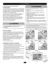
prefix to the number of your motor and remove the second dash (-). For example: 20-5752-33 (Motor Number) = K20-575233 (Motor Kit) ITEM 1 2 3 4 5 6 7 8 INDIVIDUAL PARTS PART# 10-18458 10-2013 73-18457 10-G0326 23-3001 23-3005 76-G0564 K001A5566 12-2002 DESCRIPTION Side Plate Cover Mounting Bracket Frame Assembly ... K75-18366 08-2001 10-2011 70-18618 10-3900 12-10172 07-2103 Arm Assembly Kit Rod End Fitting Gate Bracket Extension Arm Galvanized Tube 39" OD 1" IDx1.315" Sleeve Bearing Actuator Arm Stop 06-2025-T Actuator Arm Assembly K75-18367 Drive Assembly Kit (Motor ...
prefix to the number of your motor and remove the second dash (-). For example: 20-5752-33 (Motor Number) = K20-575233 (Motor Kit) ITEM 1 2 3 4 5 6 7 8 INDIVIDUAL PARTS PART# 10-18458 10-2013 73-18457 10-G0326 23-3001 23-3005 76-G0564 K001A5566 12-2002 DESCRIPTION Side Plate Cover Mounting Bracket Frame Assembly ... K75-18366 08-2001 10-2011 70-18618 10-3900 12-10172 07-2103 Arm Assembly Kit Rod End Fitting Gate Bracket Extension Arm Galvanized Tube 39" OD 1" IDx1.315" Sleeve Bearing Actuator Arm Stop 06-2025-T Actuator Arm Assembly K75-18367 Drive Assembly Kit (Motor ...

SW490 GL BOARD Manual
Page 39
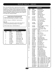
...G65MGS205 PHOTO-ELECTRIC CONTROLS DESCRIPTION Photocell/Electric Eye - 30' (9 m) Maximum Range SENSING EDGES DESCRIPTION Miller MG020 2-wire electric edge for gates. VARIABLE PARTS - Miller MG020 2-wire electric edge for gates. Miller MGR20 2-wire electric edge in 5' (1.5 m) lengths for secondary entrapment protection. Requires mounting channel (4' [1.2 m] long). Requires... for 2" (5 cm) round post. VOLTAGE +24V ac/dc 39 SW490 PART 20-XXXX (Motor) 23-XXXX (Switch) 24-XXX-X (Relay) 25-20XX (Overload) 25-40XX (Overload) PART NO. 20-1050-1T 20-1075-1T 20-1100B-2T 20-3050-1T ...
...G65MGS205 PHOTO-ELECTRIC CONTROLS DESCRIPTION Photocell/Electric Eye - 30' (9 m) Maximum Range SENSING EDGES DESCRIPTION Miller MG020 2-wire electric edge for gates. VARIABLE PARTS - Miller MG020 2-wire electric edge for gates. Miller MGR20 2-wire electric edge in 5' (1.5 m) lengths for secondary entrapment protection. Requires mounting channel (4' [1.2 m] long). Requires... for 2" (5 cm) round post. VOLTAGE +24V ac/dc 39 SW490 PART 20-XXXX (Motor) 23-XXXX (Switch) 24-XXX-X (Relay) 25-20XX (Overload) 25-40XX (Overload) PART NO. 20-1050-1T 20-1075-1T 20-1100B-2T 20-3050-1T ...
SW490 GL BOARD Manual
Page 40
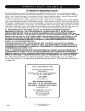
... defect in its entirety. THIS LIMITED WARRANTY DOES NOT COVER ANY PROBLEMS WITH, OR RELATING TO, THE GATE OR GATE HARDWARE, INCLUDING BUT NOT LIMITED TO THE GATE ALIGNMENT OR HINGES. ANY SERVICE CALL THAT DETERMINES THE PROBLEM HAS BEEN CAUSED BY ANY OF THESE ITEMS ...SERVICE ORGANIZATION SPANS AMERICA FOR INSTALLATION AND SERVICE INFORMATION, CALL OUR TOLL FREE NUMBER 1-800-528-2806 www.liftmaster.com WHEN ORDERING REPAIR PARTS PLEASE SUPPLY THE FOLLOWING INFORMATION: PART NUMBER DESCRIPTION MODEL NUMBER ADDRESS ORDER TO: THE CHAMBERLAIN GROUP, INC. You will void this product is originally...
... defect in its entirety. THIS LIMITED WARRANTY DOES NOT COVER ANY PROBLEMS WITH, OR RELATING TO, THE GATE OR GATE HARDWARE, INCLUDING BUT NOT LIMITED TO THE GATE ALIGNMENT OR HINGES. ANY SERVICE CALL THAT DETERMINES THE PROBLEM HAS BEEN CAUSED BY ANY OF THESE ITEMS ...SERVICE ORGANIZATION SPANS AMERICA FOR INSTALLATION AND SERVICE INFORMATION, CALL OUR TOLL FREE NUMBER 1-800-528-2806 www.liftmaster.com WHEN ORDERING REPAIR PARTS PLEASE SUPPLY THE FOLLOWING INFORMATION: PART NUMBER DESCRIPTION MODEL NUMBER ADDRESS ORDER TO: THE CHAMBERLAIN GROUP, INC. You will void this product is originally...
SW490 S3 BOARD Manual
Page 2
... 18 Programming 19 Switch #1: Operator Programming 19 Switch #2: Timer to Close 20 Controls and Accessory Installation 21 Manual Operation and System Check-Out 22 SW470 Manual Gate Operation 22 Preliminary System Check Out 22 Required Maintenance - Normal Usage 23 Troubleshooting 24 SW470 Parts List and Drawing 25 SW470 Exploded View 25 Doc 01-G0665 Rev C
... 18 Programming 19 Switch #1: Operator Programming 19 Switch #2: Timer to Close 20 Controls and Accessory Installation 21 Manual Operation and System Check-Out 22 SW470 Manual Gate Operation 22 Preliminary System Check Out 22 Required Maintenance - Normal Usage 23 Troubleshooting 24 SW470 Parts List and Drawing 25 SW470 Exploded View 25 Doc 01-G0665 Rev C
SW490 S3 BOARD Manual
Page 3
Doc 01-G0665 Rev C Please leave this manual at the job site, preferably with the end user or facility manager. Contents 3 SW470 Parts List 26 SW490 Parts List and Drawing 27 SW490 Exploded View 27 SW490 Parts List 28 Warranty Policy 30 IMPORTANT! Read and follow all instructions. This gate operator is intended for use on a gate that swings in an arc in a horizontal plane.
Doc 01-G0665 Rev C Please leave this manual at the job site, preferably with the end user or facility manager. Contents 3 SW470 Parts List 26 SW490 Parts List and Drawing 27 SW490 Exploded View 27 SW490 Parts List 28 Warranty Policy 30 IMPORTANT! Read and follow all instructions. This gate operator is intended for use on a gate that swings in an arc in a horizontal plane.
SW490 S3 BOARD Manual
Page 4
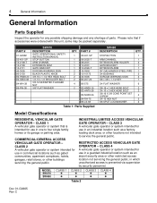
... buildings servicing the general public. CLASS 3 ! ! Table 2 Doc 01-G0665 Rev C CLASS 3 A vehicular gate operator or system intended for any possible shipping damage and any shortage of parts. RESTRICTED ACCESS VEHICULAR GATE OPERATOR - MODEL SW470 SW490 CLASS 1 ! ! CLASS 2 ! ! CLASS 1 A vehicular gate operator or system that if accessories were ordered with this unit, some may be...
... buildings servicing the general public. CLASS 3 ! ! Table 2 Doc 01-G0665 Rev C CLASS 3 A vehicular gate operator or system intended for any possible shipping damage and any shortage of parts. RESTRICTED ACCESS VEHICULAR GATE OPERATOR - MODEL SW470 SW490 CLASS 1 ! ! CLASS 2 ! ! CLASS 1 A vehicular gate operator or system that if accessories were ordered with this unit, some may be...
SW490 S3 BOARD Manual
Page 6
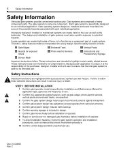
... component part of operator. 9 To avoid installation hazards, review the gate system operation and installation procedures, such as gate edges, photo-electric sensors, vertical posts and enclosed tracks, are highlighted with a precautionary symbol (see left margin). Each gate system is.... 10 Confirm control design prohibits unauthorized use . Therefore, safety features must be comprehensive. Specific safety features include: Gate Edges Enclosed Track Vertical Posts Guards for an individual application. Failure to highlight certain safety related issues. Safety Instructions ...
... component part of operator. 9 To avoid installation hazards, review the gate system operation and installation procedures, such as gate edges, photo-electric sensors, vertical posts and enclosed tracks, are highlighted with a precautionary symbol (see left margin). Each gate system is.... 10 Confirm control design prohibits unauthorized use . Therefore, safety features must be comprehensive. Specific safety features include: Gate Edges Enclosed Track Vertical Posts Guards for an individual application. Failure to highlight certain safety related issues. Safety Instructions ...
SW490 S3 BOARD Manual
Page 7
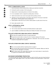
...operator inside fence line. Use photo eyes, safety edges or both the open and close directions. STEP 3: AFTER INSTALLATION 1 Test all moving parts. 3 Adjust clutch or load sensing device to minimum force setting. 4 Do not overtighten clutch or adjust force setting above minimum. 5 Install ...be taken to the operator. In any electrical connection. 2 Avoid pinch points; Warning signs must be taken during the wiring of gate system. 3 Leave Installation and Maintenance Manual and Safety Information with or obstructed. DO NOT install operator on page 8. SECONDARY ENTRAPMENT ...
...operator inside fence line. Use photo eyes, safety edges or both the open and close directions. STEP 3: AFTER INSTALLATION 1 Test all moving parts. 3 Adjust clutch or load sensing device to minimum force setting. 4 Do not overtighten clutch or adjust force setting above minimum. 5 Install ...be taken to the operator. In any electrical connection. 2 Avoid pinch points; Warning signs must be taken during the wiring of gate system. 3 Leave Installation and Maintenance Manual and Safety Information with or obstructed. DO NOT install operator on page 8. SECONDARY ENTRAPMENT ...
SW490 S3 BOARD Manual
Page 26
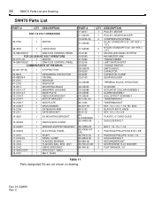
...TINNERMAN NUT 1 TINNERMAN NUT 1 KEY, 1/4 x 1/4 x 1 1/4: RD. Doc 01-G0665 Rev C 26 SW470 Parts List and Drawing SW470 Parts List PART # QTY DESCRIPTION FOR 115 VOLT OPERATORS 20-2100 1 MOTOR 29-3530 1 CAPACITOR 74-SW4705011 1 SW470 S3 CONTROL PANEL FOR 230 50/60 HZ VOLT OPERATORS 20-2101-LD 1 MOTOR 74-SW4705021...ARM HUB 1 ARM STOP 2 MOUNTING ANGLE 1 WRAPPER, HOUSING 1 BASE PLATE 1 REDUCER BRACKET 1 MOTOR BRACKET 2 SIDE PLATE 1 ARM CHANNEL 1 EXTENSION ARM 1 GATE BRACKET 10-3620 1 S3 MOUNTING BRACKET 10-G0326 10-G0387 10-G0604 11-2101 11-2103 (N) 12-3000 12-4164 15-2142 15-40B12-EEF...
...TINNERMAN NUT 1 TINNERMAN NUT 1 KEY, 1/4 x 1/4 x 1 1/4: RD. Doc 01-G0665 Rev C 26 SW470 Parts List and Drawing SW470 Parts List PART # QTY DESCRIPTION FOR 115 VOLT OPERATORS 20-2100 1 MOTOR 29-3530 1 CAPACITOR 74-SW4705011 1 SW470 S3 CONTROL PANEL FOR 230 50/60 HZ VOLT OPERATORS 20-2101-LD 1 MOTOR 74-SW4705021...ARM HUB 1 ARM STOP 2 MOUNTING ANGLE 1 WRAPPER, HOUSING 1 BASE PLATE 1 REDUCER BRACKET 1 MOTOR BRACKET 2 SIDE PLATE 1 ARM CHANNEL 1 EXTENSION ARM 1 GATE BRACKET 10-3620 1 S3 MOUNTING BRACKET 10-G0326 10-G0387 10-G0604 11-2101 11-2103 (N) 12-3000 12-4164 15-2142 15-40B12-EEF...

SW490 S3 BOARD Manual
Page 28
...12-2125 12-10172 15-2002 15-9020 16-4L280 17-2002 17-2701 18-2001 (N) 19-2075 QTY. 1 1 1 1 2 2 1 1 2 1 1 1 1 1 1 1 1 1 1 1 2 1 1 1 1 1 4 1 DESCRIPTION STANDARD PARTS PART NO. STOP BUTTON 19-9024 REVERSING CONTACTOR 24VAC 23-2016 DIN RAIL 23-3001 ARM ASSEMBLY EXTENSION ARM HOLDER SIDE PLATE SWITCH PLATE... GATE BRACKET MOUNTING ANGLE HOUSING EXTENSION ARM ARM SHAFT SWITCH BOX COVER SENSOR SUPPORT BRACKET ELECTRICAL PANEL CONTROL BOARD BRACKET MAIN SHAFT ...
...12-2125 12-10172 15-2002 15-9020 16-4L280 17-2002 17-2701 18-2001 (N) 19-2075 QTY. 1 1 1 1 2 2 1 1 2 1 1 1 1 1 1 1 1 1 1 1 2 1 1 1 1 1 4 1 DESCRIPTION STANDARD PARTS PART NO. STOP BUTTON 19-9024 REVERSING CONTACTOR 24VAC 23-2016 DIN RAIL 23-3001 ARM ASSEMBLY EXTENSION ARM HOLDER SIDE PLATE SWITCH PLATE... GATE BRACKET MOUNTING ANGLE HOUSING EXTENSION ARM ARM SHAFT SWITCH BOX COVER SENSOR SUPPORT BRACKET ELECTRICAL PANEL CONTROL BOARD BRACKET MAIN SHAFT ...


