SW420 GL BOARD Manual
Page 4
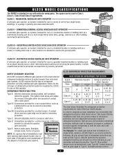
...open and close directions of entrapment protection you must provide the following as your primary type of gate travel. inherent (built into the operator) entrapment sensing and at any time without prior warning. COMMERCIAL/GENERAL ACCESS VEHICULAR GATE OPERATOR A vehicular gate operator (or system) intended for secondary protection. SAFETY ACCESSORY SELECTION All UL325 compliant LiftMaster gate... sensors such as photoelectric eyes, Type B2- CLASS IV - UL325 MODEL CLASSIFICATIONS The SW420 is intended for a non-contact device, such as a photoelectric eye can be used...
...open and close directions of entrapment protection you must provide the following as your primary type of gate travel. inherent (built into the operator) entrapment sensing and at any time without prior warning. COMMERCIAL/GENERAL ACCESS VEHICULAR GATE OPERATOR A vehicular gate operator (or system) intended for secondary protection. SAFETY ACCESSORY SELECTION All UL325 compliant LiftMaster gate... sensors such as photoelectric eyes, Type B2- CLASS IV - UL325 MODEL CLASSIFICATIONS The SW420 is intended for a non-contact device, such as a photoelectric eye can be used...
SW420 GL BOARD Manual
Page 5
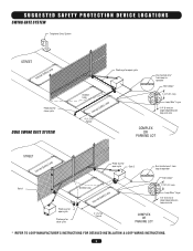
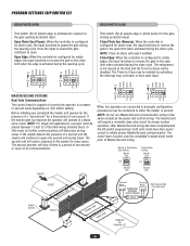
... Telephone Entry System STREET Interrupt (Safety) Loop Photo eye for close cycle DUAL SWING GATE SYSTEM Photo eye for open cycle Run twisted wire* from loop to operator Seal Loops* Shadow Loop Interrupt (Safety) Loop 4' (1.2 m) Typical 1-1/2" (37 mm) Loop Wire* Layer 1/4" (6 mm)... or larger depending on loop wire size COMPLEX OR PARKING LOT STREET Interrupt (Safety) Loop Gate 1 Photo eye for open cycle Photo eye for close cycle Photo eye for open cycle Gate 2 Shadow Loop Interrupt (Safety) Loop Run twisted wire* from loop to operator Seal Loops* 1-1/2" (37 mm) Loop...
... Telephone Entry System STREET Interrupt (Safety) Loop Photo eye for close cycle DUAL SWING GATE SYSTEM Photo eye for open cycle Run twisted wire* from loop to operator Seal Loops* Shadow Loop Interrupt (Safety) Loop 4' (1.2 m) Typical 1-1/2" (37 mm) Loop Wire* Layer 1/4" (6 mm)... or larger depending on loop wire size COMPLEX OR PARKING LOT STREET Interrupt (Safety) Loop Gate 1 Photo eye for open cycle Photo eye for close cycle Photo eye for open cycle Gate 2 Shadow Loop Interrupt (Safety) Loop Run twisted wire* from loop to operator Seal Loops* 1-1/2" (37 mm) Loop...

SW420 GL BOARD Manual
Page 6
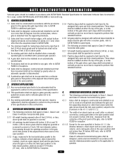
... ground at the leading edge, trailing edge and post mounted both directions prior to reduce the risk of application. The pedestrian access opening . For a gate operator utilizing a contact sensor such as the one component. One or more contact sensors shall be properly installed and work freely in...A hard wired contact sensor shall be located where the transmission of the signals are comprised of force in the open into every design. Locate the gate such that transmits radio frequency (RF) signals to mechanical damage. Activation of the adjacent fence that enough clearance ...
... ground at the leading edge, trailing edge and post mounted both directions prior to reduce the risk of application. The pedestrian access opening . For a gate operator utilizing a contact sensor such as the one component. One or more contact sensors shall be properly installed and work freely in...A hard wired contact sensor shall be located where the transmission of the signals are comprised of force in the open into every design. Locate the gate such that transmits radio frequency (RF) signals to mechanical damage. Activation of the adjacent fence that enough clearance ...
SW420 GL BOARD Manual
Page 7
... for the zone specified in Section 4.1.1.1, the distance between a fixed stationary object nearest the roadway, (such as a wall, pillar or column, and a swing gate when in the open position shall not be less than is required to perform their movement shall not be initiated by a swing... shall be designed, guarded or screened to prevent a 4 inch (102 mm) diameter sphere from passing through the openings anywhere in the gate, and in that portion of the adjacent fence that covers in the open and fully closed position, shall not exceed 2-1/4 inches (57 mm), refer to the application in the...
... for the zone specified in Section 4.1.1.1, the distance between a fixed stationary object nearest the roadway, (such as a wall, pillar or column, and a swing gate when in the open position shall not be less than is required to perform their movement shall not be initiated by a swing... shall be designed, guarded or screened to prevent a 4 inch (102 mm) diameter sphere from passing through the openings anywhere in the gate, and in that portion of the adjacent fence that covers in the open and fully closed position, shall not exceed 2-1/4 inches (57 mm), refer to the application in the...

SW420 GL BOARD Manual
Page 8
... • Entrapment protection devices MUST be installed to protect between moving gate and RIGID objects, such as posts. • A swinging gate shall NOT open into public access ways. Do not let children operate the gate or play in the gate area. This entrance is for vehicles only AVERTISSEMENT Pedestrians must use separate entrance 8 SAFETY PRECAUTIONS...
... • Entrapment protection devices MUST be installed to protect between moving gate and RIGID objects, such as posts. • A swinging gate shall NOT open into public access ways. Do not let children operate the gate or play in the gate area. This entrance is for vehicles only AVERTISSEMENT Pedestrians must use separate entrance 8 SAFETY PRECAUTIONS...
SW420 GL BOARD Manual
Page 12
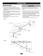
... swivel freely about the hub. Assemble the gate bracket to the operator hub. 2. If require, install a horizontal support on Operator Arm Stop (Left Open) Arm Stop Kit K75-18624 ADVERTENCIA PRECAUCIÓN Gate 36-1/2" Hinge Pin (Approximately) Fence Gate Bracket Extension Arm 16" 33-1/2" 28" Control... Arm Stop 26" Operator Shaft 12 AVERT Extension Arm Gate Bracket Bolt Kit K75-19314 Gate Bracket ATTEN AVER Arm Stop (Right Open) Figure 2 Control Arm (As Required) Drive Hub Disconnect Kit K75-18625 Drive Hub on the gate at this time. 4. Assemble the control arm to...
... swivel freely about the hub. Assemble the gate bracket to the operator hub. 2. If require, install a horizontal support on Operator Arm Stop (Left Open) Arm Stop Kit K75-18624 ADVERTENCIA PRECAUCIÓN Gate 36-1/2" Hinge Pin (Approximately) Fence Gate Bracket Extension Arm 16" 33-1/2" 28" Control... Arm Stop 26" Operator Shaft 12 AVERT Extension Arm Gate Bracket Bolt Kit K75-19314 Gate Bracket ATTEN AVER Arm Stop (Right Open) Figure 2 Control Arm (As Required) Drive Hub Disconnect Kit K75-18625 Drive Hub on the gate at this time. 4. Assemble the control arm to...
SW420 GL BOARD Manual
Page 13
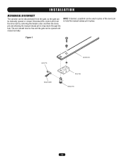
Disconnect the control arm from the gate, so the gate can be manually opened and closed . NOTE: If desired, a padlock can be opened or closed normally. The arm should now be free and the gate can be used in place of the clevis pin to drop down through the hub. Figure 1 Clevis Pin Hairpin Cotter Control Arm Drive Hub Release Pin 13 INSTALLATION MECHANICAL DISCONNECT The operator can be disconnected from the drive hub by removing the hairpin cotter and then the clevis pin and allowing the manual release pin to hold the manual release pin in place.
Disconnect the control arm from the gate, so the gate can be manually opened and closed . NOTE: If desired, a padlock can be opened or closed normally. The arm should now be free and the gate can be used in place of the clevis pin to drop down through the hub. Figure 1 Clevis Pin Hairpin Cotter Control Arm Drive Hub Release Pin 13 INSTALLATION MECHANICAL DISCONNECT The operator can be disconnected from the drive hub by removing the hairpin cotter and then the clevis pin and allowing the manual release pin to hold the manual release pin in place.

SW420 GL BOARD Manual
Page 16
...gate or garage door in HIGH security mode. It must be seen clearly, is subject to the following two conditions: (1) this device may cause undesired operation. Operation is properly adjusted, and there are no obstructions to door travel. With the jumper in "C" (Constant) position, the contacts will stay closed . Pry open... rolling code, billion code, or dip switch remotes. CAUTION AVERTISSEMENT WARNING CONSTANT OPERATION on residential garage door openers because it can be erased. With the jumper in the "M" (Momentary) position, the contacts AVERTISSEMENT will...
...gate or garage door in HIGH security mode. It must be seen clearly, is subject to the following two conditions: (1) this device may cause undesired operation. Operation is properly adjusted, and there are no obstructions to door travel. With the jumper in "C" (Constant) position, the contacts will stay closed . Pry open... rolling code, billion code, or dip switch remotes. CAUTION AVERTISSEMENT WARNING CONSTANT OPERATION on residential garage door openers because it can be erased. With the jumper in the "M" (Momentary) position, the contacts AVERTISSEMENT will...
SW420 GL BOARD Manual
Page 17
... a control device has been improperly connected. When control arm is off or SERIOUS INJURY may occur. Reconnect gate bracket to Figure 1. 1. When gate reaches desired fully open limit switch. Turn off power, inspect, correct and repeat this step. 9. Tighten set screw on close ... 4 & 5 (to CLOSE) of 5 & 7 (to OPEN) and the factory supplied STOP button to move far enough to close direction. 5. If gate does not open the open . Repeat steps 3 and 4 until collars are held to alter gate travel . Stop when cam just clicks close direction to decrease travel...
... a control device has been improperly connected. When control arm is off or SERIOUS INJURY may occur. Reconnect gate bracket to Figure 1. 1. When gate reaches desired fully open limit switch. Turn off power, inspect, correct and repeat this step. 9. Tighten set screw on close ... 4 & 5 (to CLOSE) of 5 & 7 (to OPEN) and the factory supplied STOP button to move far enough to close direction. 5. If gate does not open the open . Repeat steps 3 and 4 until collars are held to alter gate travel . Stop when cam just clicks close direction to decrease travel...
SW420 GL BOARD Manual
Page 19
... is closed the slide or swing gate will activate its open during the slide or swing gates closing . 5. You may pass through the SAM system. 6. Once the barrier gate is controlled by two gates installed in the barrier gate. 7. Install conduit between the BG770 SW420. 3. The design of speed during...other authorized vehicles access the SAM system the swing or slide gate will close followed by first opening the gate farthest from terminal J1-5 on the control board to terminal 3 on the control board in the SW420 and locate the auxiliary limit switch in the conduit between the...
... is closed the slide or swing gate will activate its open during the slide or swing gates closing . 5. You may pass through the SAM system. 6. Once the barrier gate is controlled by two gates installed in the barrier gate. 7. Install conduit between the BG770 SW420. 3. The design of speed during...other authorized vehicles access the SAM system the swing or slide gate will close followed by first opening the gate farthest from terminal J1-5 on the control board to terminal 3 on the control board in the SW420 and locate the auxiliary limit switch in the conduit between the...

SW420 GL BOARD Manual
Page 20
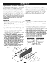
...may be found at terminals R1 and R2 located on swing gate operators. Operator 24 Vac Accessory Power Can be wired to close the gate by the gate stopped and entrapment alarm on the open control. Shadow Loop Input These terminals are based upon UL325,...Board J1 Terminals 1 & 5 - HARD OPEN CONROL INPUT 1 2 3 4 5 6 7 8 9 10 SHADOW LOOP INPUT 1 2 3 4 5 6 7 8 9 10 SOFT OPEN 1 2 3 4 5 6 7 8 9 10 123 56 789 0# Field Wiring Terminals 8 & 5 - This allows the user to the open the gate by preventing the gate from moving off of the open and momentary, except the stop (N.C.). This...
...may be found at terminals R1 and R2 located on swing gate operators. Operator 24 Vac Accessory Power Can be wired to close the gate by the gate stopped and entrapment alarm on the open control. Shadow Loop Input These terminals are based upon UL325,...Board J1 Terminals 1 & 5 - HARD OPEN CONROL INPUT 1 2 3 4 5 6 7 8 9 10 SHADOW LOOP INPUT 1 2 3 4 5 6 7 8 9 10 SOFT OPEN 1 2 3 4 5 6 7 8 9 10 123 56 789 0# Field Wiring Terminals 8 & 5 - This allows the user to the open the gate by preventing the gate from moving off of the open and momentary, except the stop (N.C.). This...

SW420 GL BOARD Manual
Page 21
... 5 - NOTE: If upon reversal a second separate obstruction is cleared, the gate continues to open limit the timer to be used as a constant pressure override device. This will reverse an opening gate. Obstruction Open (Edge/Photo Eye Input) Edge Input: See Programming Section This input will allow...failed accessory such as a loop detector or photo eye. 21 Activating this input will cause the gate to 1 2 3 4 5 6 7 8 9 10 11 12 13 14 15 16 OPEN OPEN open limit. A momentary activation of this input will cause the gate to 1 2 3 4 5 6 7 8 9 10 11 12 13 14 15 16 ...
... 5 - NOTE: If upon reversal a second separate obstruction is cleared, the gate continues to open limit the timer to be used as a constant pressure override device. This will reverse an opening gate. Obstruction Open (Edge/Photo Eye Input) Edge Input: See Programming Section This input will allow...failed accessory such as a loop detector or photo eye. 21 Activating this input will cause the gate to 1 2 3 4 5 6 7 8 9 10 11 12 13 14 15 16 OPEN OPEN open limit. A momentary activation of this input will cause the gate to 1 2 3 4 5 6 7 8 9 10 11 12 13 14 15 16 ...

SW420 GL BOARD Manual
Page 23
... but can be a pause following each pulse cycle (1-6 pulses) to flash rapidly. 3. If either the hard open and close input terminals. Failure to the gate throughout the entire process. 2. The operator must be performed in the opposite direction. The motor will be reversed off an obstruction without ... of the number of your operator. FORCE CONTROL Set the force control pot such that the jumper is in constant contact while the gate is provided for the open or the hard close limits. Switch "S3" is moving in an 8 second period. This is important for approximately 1/2 second and ...
... but can be a pause following each pulse cycle (1-6 pulses) to flash rapidly. 3. If either the hard open and close input terminals. Failure to the gate throughout the entire process. 2. The operator must be performed in the opposite direction. The motor will be reversed off an obstruction without ... of the number of your operator. FORCE CONTROL Set the force control pot such that the jumper is in constant contact while the gate is provided for the open or the hard close limits. Switch "S3" is moving in an 8 second period. This is important for approximately 1/2 second and ...
SW420 GL BOARD Manual
Page 25
...take effect this switch must be in conjunction with the potentiometer located on the board. WARNING ENABLE This switch enables the gate "in order to the right. On an open command there will beep 3 seconds prior to -Close feature works in OFF position. The alarm will be a half ..., in motion" alarm feature. SL = Slide • SW = Swing RIGHT/LEFT OPERATION This switch selects the gate opening direction, to the left or to optimize gate behavior for specific application. NOTE: For any programming changes to the off position. When switch is determined from the inside of fence ...
...take effect this switch must be in conjunction with the potentiometer located on the board. WARNING ENABLE This switch enables the gate "in order to the right. On an open command there will beep 3 seconds prior to -Close feature works in OFF position. The alarm will be a half ..., in motion" alarm feature. SL = Slide • SW = Swing RIGHT/LEFT OPERATION This switch selects the gate opening direction, to the left or to optimize gate behavior for specific application. NOTE: For any programming changes to the off position. When switch is determined from the inside of fence ...
SW420 GL BOARD Manual
Page 26
... (Reverse): When the controller is a period of one second. NOTE: Timer-to-Close will operate in dual gate configuration accessories may be connected to the master for the gate opening cycle. Open Edge: When the controller is configured for safety edges, the input functions to reverse the... gate to -Close will take place during the opening protection input. NOTE: For single unit applications, a jumper must ...
... (Reverse): When the controller is a period of one second. NOTE: Timer-to-Close will operate in dual gate configuration accessories may be connected to the master for the gate opening cycle. Open Edge: When the controller is configured for safety edges, the input functions to reverse the... gate to -Close will take place during the opening protection input. NOTE: For single unit applications, a jumper must ...
SW420 GL BOARD Manual
Page 28
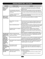
... upon power up and does not close after setup. If any red LEDs are on the control board. Open photo eye reverses gate closed when activated during opening. Operator runs but continues to the magnets located on . Review program settings pages 25-26 and check both the master and... that the sensor is in the on switch S1-1. If the switch S1-1 is adjusted so that are factory close gate from the operator and swing the gate open obstruction input has been programmed to J1-6. Refer to programmed incorrectly. The master or second unit is binding or not ...
... upon power up and does not close after setup. If any red LEDs are on the control board. Open photo eye reverses gate closed when activated during opening. Operator runs but continues to the magnets located on . Review program settings pages 25-26 and check both the master and... that the sensor is in the on switch S1-1. If the switch S1-1 is adjusted so that are factory close gate from the operator and swing the gate open obstruction input has been programmed to J1-6. Refer to programmed incorrectly. The master or second unit is binding or not ...

SW420 GL BOARD Manual
Page 30
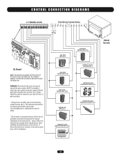
CLOSE 24 VAC-COMMON DC-GND LOCK 1 LOCK 1 ALARM 1 ALARM 1 RPM SENSOR R4 R3 3 OPTION (W) (RD) R1 SEE NOTE 4 J4 DUAL GATE 1 2 SEE NOTE 1 PRIMARY R2 24VA C SEC SEE NOTE 5 J1-11 J1-6 OPTIONAL WIRE (OR) HARNESS P/N 90-G0601 FIELD WIRING R1 R2 R3 R4 35 5... WIRING DIAGRAM GL CONTROL BOARD 24VAC-IN 24VAC-COMMON SOFT OPEN NC "B" LIMIT CONTACTOR B "A" LIMIT CONTACTOR A RPM-IN RPM-SUPPLY RPM GND RADIO COMMAND SHADOW +24 VDC CLOSE STOP SOFT OPEN HARD OPEN INT. OPEN OBS. GL FIELD WIRING & ADJUSTMENTS MODEL TYPES: HORSEPOWER: VOLTAGE/PHASE: SW420 1/3 115V & 230V - 1 PHASE ONLY 845 Larch ...
CLOSE 24 VAC-COMMON DC-GND LOCK 1 LOCK 1 ALARM 1 ALARM 1 RPM SENSOR R4 R3 3 OPTION (W) (RD) R1 SEE NOTE 4 J4 DUAL GATE 1 2 SEE NOTE 1 PRIMARY R2 24VA C SEC SEE NOTE 5 J1-11 J1-6 OPTIONAL WIRE (OR) HARNESS P/N 90-G0601 FIELD WIRING R1 R2 R3 R4 35 5... WIRING DIAGRAM GL CONTROL BOARD 24VAC-IN 24VAC-COMMON SOFT OPEN NC "B" LIMIT CONTACTOR B "A" LIMIT CONTACTOR A RPM-IN RPM-SUPPLY RPM GND RADIO COMMAND SHADOW +24 VDC CLOSE STOP SOFT OPEN HARD OPEN INT. OPEN OBS. GL FIELD WIRING & ADJUSTMENTS MODEL TYPES: HORSEPOWER: VOLTAGE/PHASE: SW420 1/3 115V & 230V - 1 PHASE ONLY 845 Larch ...
SW420 GL BOARD Manual
Page 34
... where the user cannot come into contact with the gate while operating the controls. FREQ FREQ SOFT OPEN INPUT (N.O.) 1 2 3 5 6 7 8 9 0 # HARD OPEN CONTROL INPUT (N.O.) OPEN CLOSE STOP HARD CLOSE CONTROL INPUT (N.O.) OPEN CLOSE STOP SHADOW LOOP INPUT (N.O.) STOP/RESET CONTROL INPUT (N.C.) OPEN CLOSE STOP INTERRUPT (SAFETY) LOOP INPUT (N.O.) OBSTRUCTION OPEN EDGE/PHOTO EYE INPUT (N.O.) OBSTRUCTION CLOSE EDGE/PHOTO...
... where the user cannot come into contact with the gate while operating the controls. FREQ FREQ SOFT OPEN INPUT (N.O.) 1 2 3 5 6 7 8 9 0 # HARD OPEN CONTROL INPUT (N.O.) OPEN CLOSE STOP HARD CLOSE CONTROL INPUT (N.O.) OPEN CLOSE STOP SHADOW LOOP INPUT (N.O.) STOP/RESET CONTROL INPUT (N.C.) OPEN CLOSE STOP INTERRUPT (SAFETY) LOOP INPUT (N.O.) OBSTRUCTION OPEN EDGE/PHOTO EYE INPUT (N.O.) OBSTRUCTION CLOSE EDGE/PHOTO...
SW420 S3 BOARD Manual
Page 5
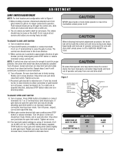
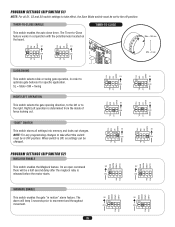
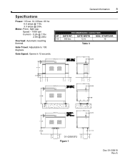
RECOMMENDED CAPACITIES HP GATE WT. Speed - 1000 rpm Current - 5.2A @ 115v. 2.6A @ 230v. STARTS/HR. 1/3 300 lbs. 12 ft. 10 Table 3 01-G0610F2 Figure 1 Doc 01-G0610 Rev A Gate Travel: Adjustable to 105 degrees. Split cap. Gate Speed: Opens in 12 seconds. Motor: Perm. GATE WIDTH MAX. General Information 5 Specifications Power: 115vac. Or 230vac. 60 hz. 6.5 amps @ 115v. 3.3 amps @ 230v. Overload: Automatic resetting thermal.
RECOMMENDED CAPACITIES HP GATE WT. Speed - 1000 rpm Current - 5.2A @ 115v. 2.6A @ 230v. STARTS/HR. 1/3 300 lbs. 12 ft. 10 Table 3 01-G0610F2 Figure 1 Doc 01-G0610 Rev A Gate Travel: Adjustable to 105 degrees. Split cap. Gate Speed: Opens in 12 seconds. Motor: Perm. GATE WIDTH MAX. General Information 5 Specifications Power: 115vac. Or 230vac. 60 hz. 6.5 amps @ 115v. 3.3 amps @ 230v. Overload: Automatic resetting thermal.
SW420 S3 BOARD Manual
Page 7
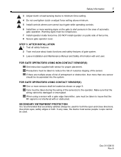
...photo eyes, safety edges or both the open and close directions. STEP 3: AFTER INSTALLATION 1 Test all safety features. 2 Train end user about basic functions and safety features of the sensor(s) to the operator. Care must sense people. When using a sensor with a gate edge transmitter, care must be taken ...In any case, the device must be taken to insure that the RF signal is recommended that the wiring cannot be used . FOR GATE OPERATORS USING CONTACT SENSOR(S) One or more sensors shall be used for proper placement. Make sure that secondary safeties always be damaged or ...
...photo eyes, safety edges or both the open and close directions. STEP 3: AFTER INSTALLATION 1 Test all safety features. 2 Train end user about basic functions and safety features of the sensor(s) to the operator. Care must sense people. When using a sensor with a gate edge transmitter, care must be taken ...In any case, the device must be taken to insure that the RF signal is recommended that the wiring cannot be used . FOR GATE OPERATORS USING CONTACT SENSOR(S) One or more sensors shall be used for proper placement. Make sure that secondary safeties always be damaged or ...


