SW420 GL BOARD Manual
Page 2
... 9 Pad Mounting 10 Pedestal Mounting 11 Control Arm Assembly 12 Mechanical Disconnect 13 WIRING Power Wiring Installation 14 On/Off Switch Power Wiring 15 Stop/Reset Button Control Wiring (Required 15 ADJUSTMENT Programming the Radio Receiver 16 Limit Switch Adjustment 17 RPM Sensor (Hall Effect) Adjustment 18 Sequenced Access Management System (SAMS 19 Accessory Wiring 20-21 Control Board Illustration 22 Controller Programming and Features 23-24 Program Settings 25-26 TROUBLESHOOTING 27-28 MAINTENANCE Operator Maintenance 29 Single Phase Wiring Diagram 30 Repair Parts 31...
... 9 Pad Mounting 10 Pedestal Mounting 11 Control Arm Assembly 12 Mechanical Disconnect 13 WIRING Power Wiring Installation 14 On/Off Switch Power Wiring 15 Stop/Reset Button Control Wiring (Required 15 ADJUSTMENT Programming the Radio Receiver 16 Limit Switch Adjustment 17 RPM Sensor (Hall Effect) Adjustment 18 Sequenced Access Management System (SAMS 19 Accessory Wiring 20-21 Control Board Illustration 22 Controller Programming and Features 23-24 Program Settings 25-26 TROUBLESHOOTING 27-28 MAINTENANCE Operator Maintenance 29 Single Phase Wiring Diagram 30 Repair Parts 31...
SW420 GL BOARD Manual
Page 5
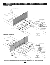
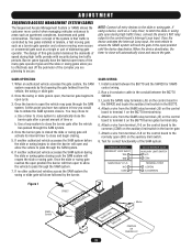
... SAFETY PROTECTION DEVICE LOCATIONS SWING GATE SYSTEM Telephone Entry System STREET Interrupt (Safety) Loop Photo eye for close cycle DUAL SWING GATE SYSTEM Photo eye for open cycle Run twisted wire* from loop to operator Seal Loops* Shadow Loop Interrupt (Safety) Loop 4' (1.2 m) Typical 1-1/2" (37 mm) Loop Wire* Layer 1/4" (6 mm) or larger depending on loop wire size COMPLEX OR PARKING LOT STREET Interrupt (Safety) Loop Gate 1 Photo eye for open cycle Photo eye for close cycle Photo eye for open cycle Gate 2 Shadow Loop Interrupt (Safety) Loop Run twisted wire* from loop to operator...
... SAFETY PROTECTION DEVICE LOCATIONS SWING GATE SYSTEM Telephone Entry System STREET Interrupt (Safety) Loop Photo eye for close cycle DUAL SWING GATE SYSTEM Photo eye for open cycle Run twisted wire* from loop to operator Seal Loops* Shadow Loop Interrupt (Safety) Loop 4' (1.2 m) Typical 1-1/2" (37 mm) Loop Wire* Layer 1/4" (6 mm) or larger depending on loop wire size COMPLEX OR PARKING LOT STREET Interrupt (Safety) Loop Gate 1 Photo eye for open cycle Photo eye for close cycle Photo eye for open cycle Gate 2 Shadow Loop Interrupt (Safety) Loop Run twisted wire* from loop to operator...

SW420 GL BOARD Manual
Page 6
... through the gate to prevent unauthorized use conditions. Outdoor or easily accessible controls shall have a security feature to operate the controls. For a gate operator utilizing a non-contact sensor: a. SAFETY INSTALLATION INFORMATION 1. All exposed pinch points are comprised of the vehicular gate. 6. Swinging gates shall not open position. The Stop and/or Reset (if provided separately) must be installed, one component. One or more contact sensors shall be located and its wiring arranged...
... through the gate to prevent unauthorized use conditions. Outdoor or easily accessible controls shall have a security feature to operate the controls. For a gate operator utilizing a non-contact sensor: a. SAFETY INSTALLATION INFORMATION 1. All exposed pinch points are comprised of the vehicular gate. 6. Swinging gates shall not open position. The Stop and/or Reset (if provided separately) must be installed, one component. One or more contact sensors shall be located and its wiring arranged...
SW420 GL BOARD Manual
Page 7
... not be designed, constructed and installed in Section 4.1.1.1, the distance between the gate and the supporting structure or other fixed object when the gate moves toward the fully open position. 2. These stops shall be required to limit travel to the designed fully open and fully closed positions. For a copy, contact ASTM directly at that covers in the open position. 3.1.3 A gap, measured in the...
... not be designed, constructed and installed in Section 4.1.1.1, the distance between the gate and the supporting structure or other fixed object when the gate moves toward the fully open position. 2. These stops shall be required to limit travel to the designed fully open and fully closed positions. For a copy, contact ASTM directly at that covers in the open position. 3.1.3 A gap, measured in the...
SW420 GL BOARD Manual
Page 14
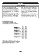
... wiring diagram. The location of the power disconnect should be dedicated and protected. WIRE GAUGE 8 • 1/3 HP Motor ----------- 432ft. 1942ft. Local codes and conditions must be cleared and secured, at the fuse box BEFORE proceeding. Upon completion of maintenance the area MUST be installed on ITS OWN separate circuits WIRE GAUGE 6 • 1/3 HP Motor ----------- ATTENTION POWER WIRING INSTALLATION Wiring SpecifiAcatiVonEs (SRTRTANIDSEDSCEOPMPEREWNIRET) On a Dual Gate System, each unit must be returned to service. Operator...
... wiring diagram. The location of the power disconnect should be dedicated and protected. WIRE GAUGE 8 • 1/3 HP Motor ----------- 432ft. 1942ft. Local codes and conditions must be cleared and secured, at the fuse box BEFORE proceeding. Upon completion of maintenance the area MUST be installed on ITS OWN separate circuits WIRE GAUGE 6 • 1/3 HP Motor ----------- ATTENTION POWER WIRING INSTALLATION Wiring SpecifiAcatiVonEs (SRTRTANIDSEDSCEOPMPEREWNIRET) On a Dual Gate System, each unit must be returned to service. Operator...

SW420 GL BOARD Manual
Page 16
... garage door. With the jumper in HIGH security mode. All remote control codes are now erased. Alternately, it overrides the safety reversal devices. AVERTISSEMENT position to opener (Figure 3). AVERTISSEMENT previous remote control codes must be used with remote When changing from electrocution: • Be sure power is NOT connected BEFORE installing the receiver. Pry open the front panel of constant closure is PROHIBITED. Press and release the "learn " button on the output contacts. The learn indicator light...
... garage door. With the jumper in HIGH security mode. All remote control codes are now erased. Alternately, it overrides the safety reversal devices. AVERTISSEMENT position to opener (Figure 3). AVERTISSEMENT previous remote control codes must be used with remote When changing from electrocution: • Be sure power is NOT connected BEFORE installing the receiver. Pry open the front panel of constant closure is PROHIBITED. Press and release the "learn " button on the output contacts. The learn indicator light...
SW420 GL BOARD Manual
Page 17
... both switch settings by set screws. If not, loosen all set screw on fully closed gate) press STOP button or release terminals to alter gate travel . Press OPEN button (if installed) or connect terminals 5 & 7 on power, disconnect extension arm from gate bracket so gate is off or SERIOUS INJURY may have been made. Turn off power, connect terminals 5 & 7 to decrease travel . Rotate cam away from close limit switch has been prematurely actuated. WARNING CAUTION AVERT When following limit switch adjustment procedure, the motor belt will turn...
... both switch settings by set screws. If not, loosen all set screw on fully closed gate) press STOP button or release terminals to alter gate travel . Press OPEN button (if installed) or connect terminals 5 & 7 on power, disconnect extension arm from gate bracket so gate is off or SERIOUS INJURY may have been made. Turn off power, connect terminals 5 & 7 to decrease travel . Rotate cam away from close limit switch has been prematurely actuated. WARNING CAUTION AVERT When following limit switch adjustment procedure, the motor belt will turn...
SW420 GL BOARD Manual
Page 19
... gate operator and a slower moving more control when managing vehicular entrances to the slide or swing gate. TERMINAL BLOCK INTERRUPT LOOP INPUT TB5 TB8 SAMS RELAY AT J5 N/O COM BG770 BARRIER GATE AUXILIARY LIMIT SWITCH N/O COM TERMINAL STRIP 1 (OPEN) 3 (COMMON) Figure 1 STREET Hold Open Loop Master SAMS Conduit Second Shadow Loop Safety Loop COMPLEX OR PARKING LOT 19 NOTE: Connect all entry devices to areas such as a single or...
... gate operator and a slower moving more control when managing vehicular entrances to the slide or swing gate. TERMINAL BLOCK INTERRUPT LOOP INPUT TB5 TB8 SAMS RELAY AT J5 N/O COM BG770 BARRIER GATE AUXILIARY LIMIT SWITCH N/O COM TERMINAL STRIP 1 (OPEN) 3 (COMMON) Figure 1 STREET Hold Open Loop Master SAMS Conduit Second Shadow Loop Safety Loop COMPLEX OR PARKING LOT 19 NOTE: Connect all entry devices to areas such as a single or...

SW420 GL BOARD Manual
Page 21
... user, in emergencies, to close limit. ADJUSTMENT ACCESSORY WIRING Field Wiring Terminals 9 & 5 - OBSTRUCTION OPEN (EDGE/PHOTO EYE INPUT) 5 8 9 10 11 12 Field Wiring Terminals 10 & 5 - OBSTRUCTION CLOSE (EDGE/PHOTO EYE INPUT) 5 8 9 10 11 12 Field Wiring Terminals 3 & 5 - STOP/RESET BUTTON WIRING R1 R2 R3 R4 3 5 OPEN CLOSE STOP STOP J1 Terminals 4 & 5 - A momentary activation of this input will be used as a loop detector or photo eye. A momentary activation of this input will stop control is detected (gate edge or RPM sensor), gate will cause the gate...
... user, in emergencies, to close limit. ADJUSTMENT ACCESSORY WIRING Field Wiring Terminals 9 & 5 - OBSTRUCTION OPEN (EDGE/PHOTO EYE INPUT) 5 8 9 10 11 12 Field Wiring Terminals 10 & 5 - OBSTRUCTION CLOSE (EDGE/PHOTO EYE INPUT) 5 8 9 10 11 12 Field Wiring Terminals 3 & 5 - STOP/RESET BUTTON WIRING R1 R2 R3 R4 3 5 OPEN CLOSE STOP STOP J1 Terminals 4 & 5 - A momentary activation of this input will be used as a loop detector or photo eye. A momentary activation of this input will stop control is detected (gate edge or RPM sensor), gate will cause the gate...

SW420 GL BOARD Manual
Page 23
.... MOTOR LEARN BUTTON Motor Learn Button (S3) FORCE CONTROL Force Control Min Max NOTE: For LED location refer to the gate throughout the entire process. 2. Two red LEDs (OLS, CLS) are three diagnostic LEDs. The operator must be programmed to blink out diagnostic codes. DIAGNOSTICS (LEDS AND CODES) There are indicators for the open and close limits. There will need to be performed in stand alone mode. 1. Failure to differentiate between master and second during run mode Motor not learned N/A Control Input Hard Input* Removal...
.... MOTOR LEARN BUTTON Motor Learn Button (S3) FORCE CONTROL Force Control Min Max NOTE: For LED location refer to the gate throughout the entire process. 2. Two red LEDs (OLS, CLS) are three diagnostic LEDs. The operator must be programmed to blink out diagnostic codes. DIAGNOSTICS (LEDS AND CODES) There are indicators for the open and close limits. There will need to be performed in stand alone mode. 1. Failure to differentiate between master and second during run mode Motor not learned N/A Control Input Hard Input* Removal...
SW420 GL BOARD Manual
Page 26
... mode depending on (S4) switch setting. Once the input is configured for proper system operation. Open Edge: When the controller is cleared the gate continues to the close cycle. If the master detects the presence of a second unit the master will reset if enabled. The Second unit will stop circuit for safety edges, the input functions to reverse the gate to open limit when activated during travel . PROGRAM SETTINGS (DIP SWITCH S2) EDGE/PHOTO OPEN EDGE/PHOTO CLOSE...
... mode depending on (S4) switch setting. Once the input is configured for proper system operation. Open Edge: When the controller is cleared the gate continues to the close cycle. If the master detects the presence of a second unit the master will reset if enabled. The Second unit will stop circuit for safety edges, the input functions to reverse the gate to open limit when activated during travel . PROGRAM SETTINGS (DIP SWITCH S2) EDGE/PHOTO OPEN EDGE/PHOTO CLOSE...
SW420 GL BOARD Manual
Page 28
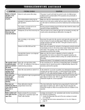
... the operator. gate edges not photo eyes. Refer to terminal J1-1 from the operator and swing the gate open and close . Locate and disconnect the end of entrapment protection devices on terminals J1-9 & J1-10 on the control board. Make sure that the gate will result in stand-alone mode. Refer to programmed incorrectly. The master or second unit is not functioning properly. Entrapment (Force Pot) incorrectly set...
... the operator. gate edges not photo eyes. Refer to terminal J1-1 from the operator and swing the gate open and close . Locate and disconnect the end of entrapment protection devices on terminals J1-9 & J1-10 on the control board. Make sure that the gate will result in stand-alone mode. Refer to programmed incorrectly. The master or second unit is not functioning properly. Entrapment (Force Pot) incorrectly set...
SW420 GL BOARD Manual
Page 29
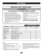
... THESE INSTRUCTIONS. Keep the remote control away from the gate. When servicing, please do some "house cleaning" of travel, retest the gate operator. Test the gate operator monthly. Disconnect ALL power BEFORE performing ANY maintenance. 9. The gate MUST reverse on contact with gate controls. Use the emergency release ONLY when the gate is within ten percent of SEVERE INJURY or DEATH: 1. Have a qualified service person make repairs to be performed by a LiftMaster professional. 10. Limit switches...
... THESE INSTRUCTIONS. Keep the remote control away from the gate. When servicing, please do some "house cleaning" of travel, retest the gate operator. Test the gate operator monthly. Disconnect ALL power BEFORE performing ANY maintenance. 9. The gate MUST reverse on contact with gate controls. Use the emergency release ONLY when the gate is within ten percent of SEVERE INJURY or DEATH: 1. Have a qualified service person make repairs to be performed by a LiftMaster professional. 10. Limit switches...

SW420 GL BOARD Manual
Page 31
...36 for all repair part ordering information. Complete Electrical Panel Replacement Kits To order a complete electrical box replacement kit, add a K- For example: SW420-33-11 (Operator) = K73SW420-33-11 (Electrical Box Kit) Motor Kits To order a motor replacement kit, add a K prefix to the model number of individual components. SPST 2 Reducer 30:1 1 Limit Collar 1 Hall Effect Assembly 1 Roll Pin 2 Belt 1 Molded Pulley 1 Spacer 1 Washer 7 Phillips Screw 10-32x2-1/2" 1 31 Individual components of your operator. Please consult a parts and service representative...
...36 for all repair part ordering information. Complete Electrical Panel Replacement Kits To order a complete electrical box replacement kit, add a K- For example: SW420-33-11 (Operator) = K73SW420-33-11 (Electrical Box Kit) Motor Kits To order a motor replacement kit, add a K prefix to the model number of individual components. SPST 2 Reducer 30:1 1 Limit Collar 1 Hall Effect Assembly 1 Roll Pin 2 Belt 1 Molded Pulley 1 Spacer 1 Washer 7 Phillips Screw 10-32x2-1/2" 1 31 Individual components of your operator. Please consult a parts and service representative...
SW420 GL BOARD Manual
Page 34
... instructions are to be installed where the user cannot come into contact with the gate while operating the controls. SEE OWNERS MANUAL FOR WIRING DISTANCES AND WIRE GAUGE INFORMATION. FREQ FREQ SOFT OPEN INPUT (N.O.) 1 2 3 5 6 7 8 9 0 # HARD OPEN CONTROL INPUT (N.O.) OPEN CLOSE STOP HARD CLOSE CONTROL INPUT (N.O.) OPEN CLOSE STOP SHADOW LOOP INPUT (N.O.) STOP/RESET CONTROL INPUT (N.C.) OPEN CLOSE STOP INTERRUPT (SAFETY) LOOP INPUT (N.O.) OBSTRUCTION OPEN EDGE/PHOTO EYE INPUT (N.O.) OBSTRUCTION CLOSE EDGE/PHOTO EYE INPUT (N.O.) RESIDENTIAL RADIO (SINGLE BUTTON) INPUT (N.O.) SW420...
... instructions are to be installed where the user cannot come into contact with the gate while operating the controls. SEE OWNERS MANUAL FOR WIRING DISTANCES AND WIRE GAUGE INFORMATION. FREQ FREQ SOFT OPEN INPUT (N.O.) 1 2 3 5 6 7 8 9 0 # HARD OPEN CONTROL INPUT (N.O.) OPEN CLOSE STOP HARD CLOSE CONTROL INPUT (N.O.) OPEN CLOSE STOP SHADOW LOOP INPUT (N.O.) STOP/RESET CONTROL INPUT (N.C.) OPEN CLOSE STOP INTERRUPT (SAFETY) LOOP INPUT (N.O.) OBSTRUCTION OPEN EDGE/PHOTO EYE INPUT (N.O.) OBSTRUCTION CLOSE EDGE/PHOTO EYE INPUT (N.O.) RESIDENTIAL RADIO (SINGLE BUTTON) INPUT (N.O.) SW420...
SW420 GL BOARD Manual
Page 36
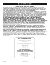
.... HOW TO ORDER REPAIR PARTS OUR LARGE SERVICE ORGANIZATION SPANS AMERICA FOR INSTALLATION AND SERVICE INFORMATION CALL OUR TOLL FREE NUMBER: 1-800-528-2806 www.liftmaster.com WHEN ORDERING REPAIR PARTS PLEASE SUPPLY THE FOLLOWING INFORMATION: PART NUMBER DESCRIPTION MODEL NUMBER ADDRESS ORDER TO: THE CHAMBERLAIN GROUP, INC. Country Club Road Tucson, AZ 85706 01-18451H © 2010, The Chamberlain Group, Inc. If, during the limited warranty period, this...
.... HOW TO ORDER REPAIR PARTS OUR LARGE SERVICE ORGANIZATION SPANS AMERICA FOR INSTALLATION AND SERVICE INFORMATION CALL OUR TOLL FREE NUMBER: 1-800-528-2806 www.liftmaster.com WHEN ORDERING REPAIR PARTS PLEASE SUPPLY THE FOLLOWING INFORMATION: PART NUMBER DESCRIPTION MODEL NUMBER ADDRESS ORDER TO: THE CHAMBERLAIN GROUP, INC. Country Club Road Tucson, AZ 85706 01-18451H © 2010, The Chamberlain Group, Inc. If, during the limited warranty period, this...
SW420 S3 BOARD Manual
Page 7
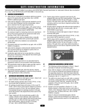
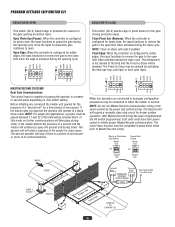
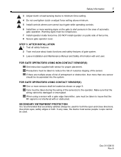
.... Safety Information 7 3 Adjust clutch or load sensing device to minimum force setting. 4 Do not overtighten clutch or adjust force setting above minimum. 5 Install controls where user cannot touch gate while operating controls. 6 Install two or more warning signs on page 8. Precautions must be taken to the operator. STEP 3: AFTER INSTALLATION 1 Test all safety features. 2 Train end user about basic functions and safety features of automatic gate operation. Use photo eyes, safety edges or both the open and close...
.... Safety Information 7 3 Adjust clutch or load sensing device to minimum force setting. 4 Do not overtighten clutch or adjust force setting above minimum. 5 Install controls where user cannot touch gate while operating controls. 6 Install two or more warning signs on page 8. Precautions must be taken to the operator. STEP 3: AFTER INSTALLATION 1 Test all safety features. 2 Train end user about basic functions and safety features of automatic gate operation. Use photo eyes, safety edges or both the open and close...
SW420 S3 BOARD Manual
Page 21
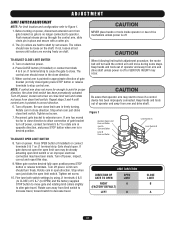
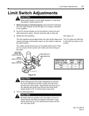
... free moving on electrical power. Doc 01-G0610 Rev A CAUTION Be aware that the gate is off . 1 Before turning on electrical power, disconnect the extension arm from gate bracket so that the operator arm may result. 4 Turn on the shaft. AUXILIARY OPEN LIMIT CAM & COLLAR LIMIT A CAM & COLLAR LIMIT B CAM & COLLAR LIMIT SWITCH A LIMIT SWITCH B DIRECTION OF GATE TO OPEN Right Left OPEN LIMIT A B CLOSE LIMIT B A 01-G0610F15 Figure 16 CAUTION When following the limit switch adjustment procedure, the motor belt will turn and the control arm...
... free moving on electrical power. Doc 01-G0610 Rev A CAUTION Be aware that the gate is off . 1 Before turning on electrical power, disconnect the extension arm from gate bracket so that the operator arm may result. 4 Turn on the shaft. AUXILIARY OPEN LIMIT CAM & COLLAR LIMIT A CAM & COLLAR LIMIT B CAM & COLLAR LIMIT SWITCH A LIMIT SWITCH B DIRECTION OF GATE TO OPEN Right Left OPEN LIMIT A B CLOSE LIMIT B A 01-G0610F15 Figure 16 CAUTION When following the limit switch adjustment procedure, the motor belt will turn and the control arm...
SW420 S3 BOARD Manual
Page 24
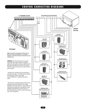
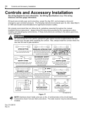
... left/right switch effects direction. See Wiring Specifications on the circuit board. For warning devices, call for persons. The following instructions are on the J1 terminal strip on p. 9 for more information. Figure 17 13 14 POWER GATE LOCK USE POWER TO MATCH GATE LOCK REQUIREMENTS, NOT TO EXCEED 115V 10A. In any control device. 24 Controls and Accessory Installation Controls and Accessory Installation See wiring diagram for wiring distances and wire gauge information. STOP BUTTON - always...
... left/right switch effects direction. See Wiring Specifications on the circuit board. For warning devices, call for persons. The following instructions are on the J1 terminal strip on p. 9 for more information. Figure 17 13 14 POWER GATE LOCK USE POWER TO MATCH GATE LOCK REQUIREMENTS, NOT TO EXCEED 115V 10A. In any control device. 24 Controls and Accessory Installation Controls and Accessory Installation See wiring diagram for wiring distances and wire gauge information. STOP BUTTON - always...
SW420 S3 BOARD Manual
Page 34
... adapted without the prior written consent of LiftMaster. FOR TECHNICAL SUPPORT TO ORDER REPAIR PARTS Call our toll free numbers: Call our toll free numbers: (800) 323-2276 (800) 998-9197 (800) 528-2806 (800) 998-9197 Installation and service information is protected by copyright and contain information proprietary to provide the following information when ordering repair parts: Part Number Part Name Model Number COPYRIGHT 2001 ALL RIGHTS RESERVED This...
... adapted without the prior written consent of LiftMaster. FOR TECHNICAL SUPPORT TO ORDER REPAIR PARTS Call our toll free numbers: Call our toll free numbers: (800) 323-2276 (800) 998-9197 (800) 528-2806 (800) 998-9197 Installation and service information is protected by copyright and contain information proprietary to provide the following information when ordering repair parts: Part Number Part Name Model Number COPYRIGHT 2001 ALL RIGHTS RESERVED This...


