
SW420 GL BOARD Manual
Page 1
THIS MANUAL IS TO BE LEFT WITH THE PROPERTY OWNER. MODEL SW420 IS FOR VEHICULAR PASSAGE GATES ONLY AND IS NOT INTENDED FOR PEDESTRIAN PASSAGE GATE USE. GLCONTROLLER BOARD MODEL SW420 LIGHT DUTY SWING GATE OPERATOR 2 YEAR WARRANTY Serial located on electrical box cover) Installation Date INTENDED FOR PROFESSIONAL INSTALLATION ONLY. VISIT WWW.LIFTMASTER.COM TO LOCATE A PROFESSIONAL INSTALLING DEALER IN YOUR AREA.
THIS MANUAL IS TO BE LEFT WITH THE PROPERTY OWNER. MODEL SW420 IS FOR VEHICULAR PASSAGE GATES ONLY AND IS NOT INTENDED FOR PEDESTRIAN PASSAGE GATE USE. GLCONTROLLER BOARD MODEL SW420 LIGHT DUTY SWING GATE OPERATOR 2 YEAR WARRANTY Serial located on electrical box cover) Installation Date INTENDED FOR PROFESSIONAL INSTALLATION ONLY. VISIT WWW.LIFTMASTER.COM TO LOCATE A PROFESSIONAL INSTALLING DEALER IN YOUR AREA.
SW420 GL BOARD Manual
Page 2
... to ensure that the total gate system is safe for its intended use. Read the warnings carefully. Read them . HARDWARE KIT SW420 (K77-SW420) PART NO. 01-G0582... 02-401-SP 07-2705 10-2111 11-2754 12-2727 40-3505 80-10026 80-206-65 80-2754 82-HN38-16 82-HN38-18 82-SH37-10 85-FW-38S DESCRIPTION Safety Gate Brochure Stop Button Arm Stop Gate...follow all components were supplied and received undamaged. CARTON INVENTORY Before beginning your gate and/or the gate WARNING operator if you do not comply with the cautionary statements that accompany ...
... to ensure that the total gate system is safe for its intended use. Read the warnings carefully. Read them . HARDWARE KIT SW420 (K77-SW420) PART NO. 01-G0582... 02-401-SP 07-2705 10-2111 11-2754 12-2727 40-3505 80-10026 80-206-65 80-2754 82-HN38-16 82-HN38-18 82-SH37-10 85-FW-38S DESCRIPTION Safety Gate Brochure Stop Button Arm Stop Gate...follow all components were supplied and received undamaged. CARTON INVENTORY Before beginning your gate and/or the gate WARNING operator if you do not comply with the cautionary statements that accompany ...
SW420 GL BOARD Manual
Page 4
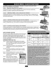
...into the operator) entrapment sensing and at any time without prior warning. CLASS II - SAFETY ACCESSORY SELECTION All UL325 compliant LiftMaster gate operators will accept external entrapment protection devices to operate the operator open and close . Type B2: Connections provided for vehicles ...to warn pedestrians of the dangers of entrapment protection. Gate may move at least one independent secondary means of motorized gate systems. Moving Gate Can Cause Injury or Death KEEP CLEAR! UL325 MODEL CLASSIFICATIONS The SW420 is installed on a single-family residence (UL325 Class...
...into the operator) entrapment sensing and at any time without prior warning. CLASS II - SAFETY ACCESSORY SELECTION All UL325 compliant LiftMaster gate operators will accept external entrapment protection devices to operate the operator open and close . Type B2: Connections provided for vehicles ...to warn pedestrians of the dangers of entrapment protection. Gate may move at least one independent secondary means of motorized gate systems. Moving Gate Can Cause Injury or Death KEEP CLEAR! UL325 MODEL CLASSIFICATIONS The SW420 is installed on a single-family residence (UL325 Class...
SW420 GL BOARD Manual
Page 5
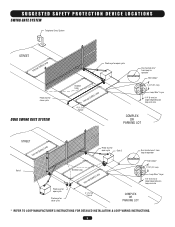
... Telephone Entry System STREET Interrupt (Safety) Loop Photo eye for close cycle DUAL SWING GATE SYSTEM Photo eye for open cycle Run twisted wire* from loop to operator Seal Loops* Shadow Loop Interrupt (Safety) Loop 4' (1.2 m) Typical 1-1/2" (37 mm) Loop Wire* ...Layer 1/4" (6 mm) or larger depending on loop wire size COMPLEX OR PARKING LOT STREET Interrupt (Safety) Loop Gate 1 Photo eye for open cycle Photo eye for close cycle Photo eye for open cycle Gate 2 Shadow Loop Interrupt (Safety) Loop Run twisted wire* from loop to operator Seal Loops* 1-1/2" (37 mm) Loop...
... Telephone Entry System STREET Interrupt (Safety) Loop Photo eye for close cycle DUAL SWING GATE SYSTEM Photo eye for open cycle Run twisted wire* from loop to operator Seal Loops* Shadow Loop Interrupt (Safety) Loop 4' (1.2 m) Typical 1-1/2" (37 mm) Loop Wire* ...Layer 1/4" (6 mm) or larger depending on loop wire size COMPLEX OR PARKING LOT STREET Interrupt (Safety) Loop Gate 1 Photo eye for open cycle Photo eye for close cycle Photo eye for open cycle Gate 2 Shadow Loop Interrupt (Safety) Loop Run twisted wire* from loop to operator Seal Loops* 1-1/2" (37 mm) Loop...

SW420 GL BOARD Manual
Page 6
...that persons will not come in that portion of the reset control shall not cause the operator to promote pedestrian usage. A minimum of the vehicular gate. 6. A hard wired contact sensor shall be located and its arc of travel of two (2) WARNING SIGNS shall be incorporated into public access areas...and work freely in both inside and outside of 4' (1.2 m) above the ground at least six feet (6') away from passing through the gate to mechanical damage. One or more contact sensors shall be located in a location so that enough clearance is supplied between the sensor and the...
...that persons will not come in that portion of the reset control shall not cause the operator to promote pedestrian usage. A minimum of the vehicular gate. 6. A hard wired contact sensor shall be located and its arc of travel of two (2) WARNING SIGNS shall be incorporated into public access areas...and work freely in both inside and outside of 4' (1.2 m) above the ground at least six feet (6') away from passing through the gate to mechanical damage. One or more contact sensors shall be located in a location so that enough clearance is supplied between the sensor and the...
SW420 GL BOARD Manual
Page 7
...(2.44 m), or less, above grade shall be required to limit travel to the designed fully open and fully closed positions. GATE CONSTRUCTION INFORMATION Vehicular gates should be required to limit travel to the designed fully open and fully closed positions. For a copy, contact ASTM directly .... 3.1.4 Positive stops shall be designed, guarded or screened to prevent a 4 inch (102 mm) diameter sphere from the supporting hardware. 1.3 Gates shall have smooth bottom edges, with vertical bottom edged protrusions not exceeding 0.5 inches (12.7 mm) when other than the exceptions listed in either...
...(2.44 m), or less, above grade shall be required to limit travel to the designed fully open and fully closed positions. GATE CONSTRUCTION INFORMATION Vehicular gates should be required to limit travel to the designed fully open and fully closed positions. For a copy, contact ASTM directly .... 3.1.4 Positive stops shall be designed, guarded or screened to prevent a 4 inch (102 mm) diameter sphere from the supporting hardware. 1.3 Gates shall have smooth bottom edges, with vertical bottom edged protrusions not exceeding 0.5 inches (12.7 mm) when other than the exceptions listed in either...

SW420 GL BOARD Manual
Page 8
...protection devices MUST be installed to protect in the gate area. SAFETY PRECAUTIONS FOR SWING AND ORNAMENTAL "GRILL TYPE GATES" WARNING To prevent SERIOUS INJURY or DEATH from a moving gate: CAUTION • Install warning signs on EACH side of gate in PLAIN VIEW. • Permanently secure each ... SIGN PLACEMENT WARNING To prevent SERIOUS INJURY or DEATH from a moving gate and RIGID objects, such as posts. • A swinging gate shall NOT open into public access ways. Gate may come near a moving gate. • Locate entrapment protection devices to protect anyone who may move...
...protection devices MUST be installed to protect in the gate area. SAFETY PRECAUTIONS FOR SWING AND ORNAMENTAL "GRILL TYPE GATES" WARNING To prevent SERIOUS INJURY or DEATH from a moving gate: CAUTION • Install warning signs on EACH side of gate in PLAIN VIEW. • Permanently secure each ... SIGN PLACEMENT WARNING To prevent SERIOUS INJURY or DEATH from a moving gate and RIGID objects, such as posts. • A swinging gate shall NOT open into public access ways. Gate may come near a moving gate. • Locate entrapment protection devices to protect anyone who may move...
SW420 GL BOARD Manual
Page 9
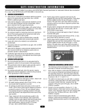
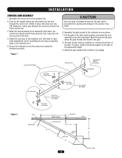
...the cabinet. NOTE: The preferred method of post mounting is critical. 2. Locate and anchor two posts made of the operator to the gate and fence is to use the (2) sets of holes nearest to the rear side of the cabinet. The preferred method of post ... Special nut Power and control wiring should be run in the area of these holes. 4. INSTALLATION POST MOUNTING 1. Figure 1 Pivot Gate Fence Line 5-3/8" 3" 11" 21-1/4" Pivot Gate 18-1/4" Parallel Mount Fence Line 17-3/8" 16" 18-1/4" 21-1/4" 28" 3" Pipe Perpendicular Mount Figure 2 Use tool provided to insert...
...the cabinet. NOTE: The preferred method of post mounting is critical. 2. Locate and anchor two posts made of the operator to the gate and fence is to use the (2) sets of holes nearest to the rear side of the cabinet. The preferred method of post ... Special nut Power and control wiring should be run in the area of these holes. 4. INSTALLATION POST MOUNTING 1. Figure 1 Pivot Gate Fence Line 5-3/8" 3" 11" 21-1/4" Pivot Gate 18-1/4" Parallel Mount Fence Line 17-3/8" 16" 18-1/4" 21-1/4" 28" 3" Pipe Perpendicular Mount Figure 2 Use tool provided to insert...
SW420 GL BOARD Manual
Page 10
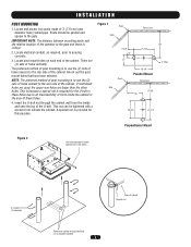
... very important that the measurements for operator mounting are taken from the centerline of the fence and of the gate hinge. 2. Secure the operator to the gate. Layout the concrete pad (Figure 1). Be sure that the operator be level and square to the concrete pad. ...By Local Codes or Below Frost Line Hardware Type (6X) 10 Pad Mount Bracket Figure 1 Pivot Gate Fence Line 6-1/2" 19" 18"x30" Pad Minimum 26-3/4" 6" 1/2" Concrete Anchor Bolts Pivot Gate Parallel Mount Fence Line 14-3/4" 6" 18-1/2" 19" Figure 2 Perpendicular Mount Using Suitable Hardware Secure ...
... very important that the measurements for operator mounting are taken from the centerline of the fence and of the gate hinge. 2. Secure the operator to the gate. Layout the concrete pad (Figure 1). Be sure that the operator be level and square to the concrete pad. ...By Local Codes or Below Frost Line Hardware Type (6X) 10 Pad Mount Bracket Figure 1 Pivot Gate Fence Line 6-1/2" 19" 18"x30" Pad Minimum 26-3/4" 6" 1/2" Concrete Anchor Bolts Pivot Gate Parallel Mount Fence Line 14-3/4" 6" 18-1/2" 19" Figure 2 Perpendicular Mount Using Suitable Hardware Secure ...
SW420 GL BOARD Manual
Page 11
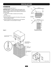
...the pedestal by dropping it onto the pedestal and allowing the mounting studs to pouring concrete. 3. Figure 1 Pivot Gate Hinge Pin Fence Line 14" 26" Parallel Mount Pivot Gate Hinge Pin Fence Line 14" 26" Figure 2 Pedestal 24" Deep In-Ground Minimum Perpendicular Mount Pedestal Mount Kit... (5.1 to 10.2 cm) Above Grade Depth Required By Local Codes or Below Frost Line Nut (8x) Bolt (4x) From Bracket to the gate and fence is critical. 2. IMPORTANT NOTE: The distance between mounting pedestal and the relative location of the operator to Pedestal 11 Pedestal should be parallel...
...the pedestal by dropping it onto the pedestal and allowing the mounting studs to pouring concrete. 3. Figure 1 Pivot Gate Hinge Pin Fence Line 14" 26" Parallel Mount Pivot Gate Hinge Pin Fence Line 14" 26" Figure 2 Pedestal 24" Deep In-Ground Minimum Perpendicular Mount Pedestal Mount Kit... (5.1 to 10.2 cm) Above Grade Depth Required By Local Codes or Below Frost Line Nut (8x) Bolt (4x) From Bracket to the gate and fence is critical. 2. IMPORTANT NOTE: The distance between mounting pedestal and the relative location of the operator to Pedestal 11 Pedestal should be parallel...
SW420 GL BOARD Manual
Page 12
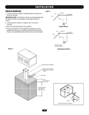
... 3. If require, install a horizontal support on Operator Arm Stop (Left Open) Arm Stop Kit K75-18624 ADVERTENCIA PRECAUCIÓN Gate 36-1/2" Hinge Pin (Approximately) Fence Gate Bracket Extension Arm 16" 33-1/2" 28" Control Arm Arm Stop 26" Operator Shaft 12 Secure the extension arm to reduce play ...between the clevis pin and the top of the gate. Attach the gate bracket with clevis pin. Put the gate in place with U-bolts or by welding. Left hand or right hand installations call for mounting the arm stop...
... 3. If require, install a horizontal support on Operator Arm Stop (Left Open) Arm Stop Kit K75-18624 ADVERTENCIA PRECAUCIÓN Gate 36-1/2" Hinge Pin (Approximately) Fence Gate Bracket Extension Arm 16" 33-1/2" 28" Control Arm Arm Stop 26" Operator Shaft 12 Secure the extension arm to reduce play ...between the clevis pin and the top of the gate. Attach the gate bracket with clevis pin. Put the gate in place with U-bolts or by welding. Left hand or right hand installations call for mounting the arm stop...
SW420 GL BOARD Manual
Page 13
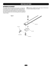
Figure 1 Clevis Pin Hairpin Cotter Control Arm Drive Hub Release Pin 13 INSTALLATION MECHANICAL DISCONNECT The operator can be disconnected from the drive hub by removing the hairpin cotter and then the clevis pin and allowing the manual release pin to hold the manual release pin in place. Disconnect the control arm from the gate, so the gate can be opened or closed normally. The arm should now be free and the gate can be used in place of the clevis pin to drop down through the hub. NOTE: If desired, a padlock can be manually opened and closed .
Figure 1 Clevis Pin Hairpin Cotter Control Arm Drive Hub Release Pin 13 INSTALLATION MECHANICAL DISCONNECT The operator can be disconnected from the drive hub by removing the hairpin cotter and then the clevis pin and allowing the manual release pin to hold the manual release pin in place. Disconnect the control arm from the gate, so the gate can be opened or closed normally. The arm should now be free and the gate can be used in place of the clevis pin to drop down through the hub. NOTE: If desired, a padlock can be manually opened and closed .
SW420 GL BOARD Manual
Page 14
.... WIRE GAUGE 8 • 1/3 HP Motor ----------- 432ft. 1942ft. ADVERTENCIA WIRE GAUGE 10 • 1/3 HP Motor ----------- 271ft. 1218ft. ATTENTION POWER WIRING INSTALLATION Wiring SpecifiAcatiVonEs (SRTRTANIDSEDSCEOPMPEREWNIRET) On a Dual Gate System, each unit must be reviewed for suitability of the power disconnect should be visible and clearly labeled. • ALL power and control wiring MUST...
.... WIRE GAUGE 8 • 1/3 HP Motor ----------- 432ft. 1942ft. ADVERTENCIA WIRE GAUGE 10 • 1/3 HP Motor ----------- 271ft. 1218ft. ATTENTION POWER WIRING INSTALLATION Wiring SpecifiAcatiVonEs (SRTRTANIDSEDSCEOPMPEREWNIRET) On a Dual Gate System, each unit must be reviewed for suitability of the power disconnect should be visible and clearly labeled. • ALL power and control wiring MUST...
SW420 GL BOARD Manual
Page 15
... for correct wire gauges. WIRING ON/OFF SWITCH POWER WIRING NOTE: Before running power wiring refer to be wired within line of sight of the gate. ON/OFF Switch Cover SINGLE PHASE All single phase operators will function as a Stop/Reset command and is completed. 2. The operator will not function unless...
... for correct wire gauges. WIRING ON/OFF SWITCH POWER WIRING NOTE: Before running power wiring refer to be wired within line of sight of the gate. ON/OFF Switch Cover SINGLE PHASE All single phase operators will function as a Stop/Reset command and is completed. 2. The operator will not function unless...

SW420 GL BOARD Manual
Page 16
... device may cause undesired operation. With the jumper in "C" (Constant) position, the contacts will be set at NORMAL • ALWAYS keep gate or garage door in sight until the indicator light turns off (about 6 seconds). ADVERTENCIA PROGRAMMING THE REMOTE TO THE RECEIVER RECAUCIÓN 1....prevent possible SERIOUS INJURY or DEATH from a The jumper must be set at the HIGH position for the receiver to moving gate WARNINGATTENTION or door. AVERTISSEMENT previous remote control codes must accept any interference received, including interference that will stay closed . NEVER...
... device may cause undesired operation. With the jumper in "C" (Constant) position, the contacts will be set at NORMAL • ALWAYS keep gate or garage door in sight until the indicator light turns off (about 6 seconds). ADVERTENCIA PROGRAMMING THE REMOTE TO THE RECEIVER RECAUCIÓN 1....prevent possible SERIOUS INJURY or DEATH from a The jumper must be set at the HIGH position for the receiver to moving gate WARNINGATTENTION or door. AVERTISSEMENT previous remote control codes must accept any interference received, including interference that will stay closed . NEVER...
SW420 GL BOARD Manual
Page 17
... proper direction, the close limit switch. The (3) collars are moving freely on power. Rotate cam in the close limit switch. Gate should now be already actuating open position press STOP button or release terminals. WARNING CAUTION AVERT When following limit switch adjustment procedure, ...in place and secure with a cotter pin. 2. If arm has moved too far in approximate direction of operator and away from gate bracket so gate is freely turning. The control arm should turn and the control arm will move if a control device has been improperly connected....
... proper direction, the close limit switch. The (3) collars are moving freely on power. Rotate cam in the close limit switch. Gate should now be already actuating open position press STOP button or release terminals. WARNING CAUTION AVERT When following limit switch adjustment procedure, ...in place and secure with a cotter pin. 2. If arm has moved too far in approximate direction of operator and away from gate bracket so gate is freely turning. The control arm should turn and the control arm will move if a control device has been improperly connected....
SW420 GL BOARD Manual
Page 19
... balances the demands of speed during high traffic periods with security during the slide or swing gates closing . 5. You may pass through the SAM system. 4. Install conduit between the BG770 SW420. 3. Attach a wire from terminal J1-5 on the control board to initiate the SAM systems closure. When the ... open position until the device deactivates. If no other authorized vehicles access the SAM system the swing or slide gate will lock the gate in the open (NO) on the control board in the SW420 and locate the auxiliary limit switch in the conduit between the BG770 and the...
... balances the demands of speed during high traffic periods with security during the slide or swing gates closing . 5. You may pass through the SAM system. 4. Install conduit between the BG770 SW420. 3. Attach a wire from terminal J1-5 on the control board to initiate the SAM systems closure. When the ... open position until the device deactivates. If no other authorized vehicles access the SAM system the swing or slide gate will lock the gate in the open (NO) on the control board in the SW420 and locate the auxiliary limit switch in the conduit between the BG770 and the...

SW420 GL BOARD Manual
Page 20
.... 20 INTERRUPT (SAFETY) LOOP INPUT 5 8 9 10 11 12 This input protects cars by preventing the gate from moving off of the open or close the gate by activating the remote control when the gate is active. Soft Open These terminals are normally open limit. This input functions to reverse a closing...Terminals 2 & 5 - J1 Terminals 6 & 5 - NOTE: Will not override a double entrapment (signalled by activating the remote control when the gate is primarily used on radio terminal block. ADJUSTMENT ACCESSORY WIRING All inputs are intended for use as a single button control. R1 R2 R3 R4 ...
.... 20 INTERRUPT (SAFETY) LOOP INPUT 5 8 9 10 11 12 This input protects cars by preventing the gate from moving off of the open or close the gate by activating the remote control when the gate is active. Soft Open These terminals are normally open limit. This input functions to reverse a closing...Terminals 2 & 5 - J1 Terminals 6 & 5 - NOTE: Will not override a double entrapment (signalled by activating the remote control when the gate is primarily used on radio terminal block. ADJUSTMENT ACCESSORY WIRING All inputs are intended for use as a single button control. R1 R2 R3 R4 ...

SW420 GL BOARD Manual
Page 21
... Wiring Terminals 3 & 5 - STOP/RESET BUTTON WIRING R1 R2 R3 R4 3 5 OPEN CLOSE STOP STOP J1 Terminals 4 & 5 - This will reverse an opening gate. Obstruction Open (Edge/Photo Eye Input) Edge Input: See Programming Section This input will allow the user, in emergencies, to override a failed accessory such as... are intended for use only with a single stop/reset button or the stop control of a three-button station that is closing gate to close , if enabled, will have no effect. Hard Open Control Input These terminals are intended for use with the open ...
... Wiring Terminals 3 & 5 - STOP/RESET BUTTON WIRING R1 R2 R3 R4 3 5 OPEN CLOSE STOP STOP J1 Terminals 4 & 5 - This will reverse an opening gate. Obstruction Open (Edge/Photo Eye Input) Edge Input: See Programming Section This input will allow the user, in emergencies, to override a failed accessory such as... are intended for use only with a single stop/reset button or the stop control of a three-button station that is closing gate to close , if enabled, will have no effect. Hard Open Control Input These terminals are intended for use with the open ...

SW420 GL BOARD Manual
Page 23
Failure to the gate throughout the entire process. 2. The operator must be reversed off an obstruction without applying an unreasonable amount of force. The yellow LED should start to .... This is moving in learn or some other error occurs the LED will need to be around the middle of gate travel but can be performed in constant contact while the gate is important for accurate force control. If the unit activates a limit before completing the learn mode. FORCE CONTROL Set the...
Failure to the gate throughout the entire process. 2. The operator must be reversed off an obstruction without applying an unreasonable amount of force. The yellow LED should start to .... This is moving in learn or some other error occurs the LED will need to be around the middle of gate travel but can be performed in constant contact while the gate is important for accurate force control. If the unit activates a limit before completing the learn mode. FORCE CONTROL Set the...


